Downloaded 66 times
![Publication No Cu0143
Issue Date: December 2015
Page 2
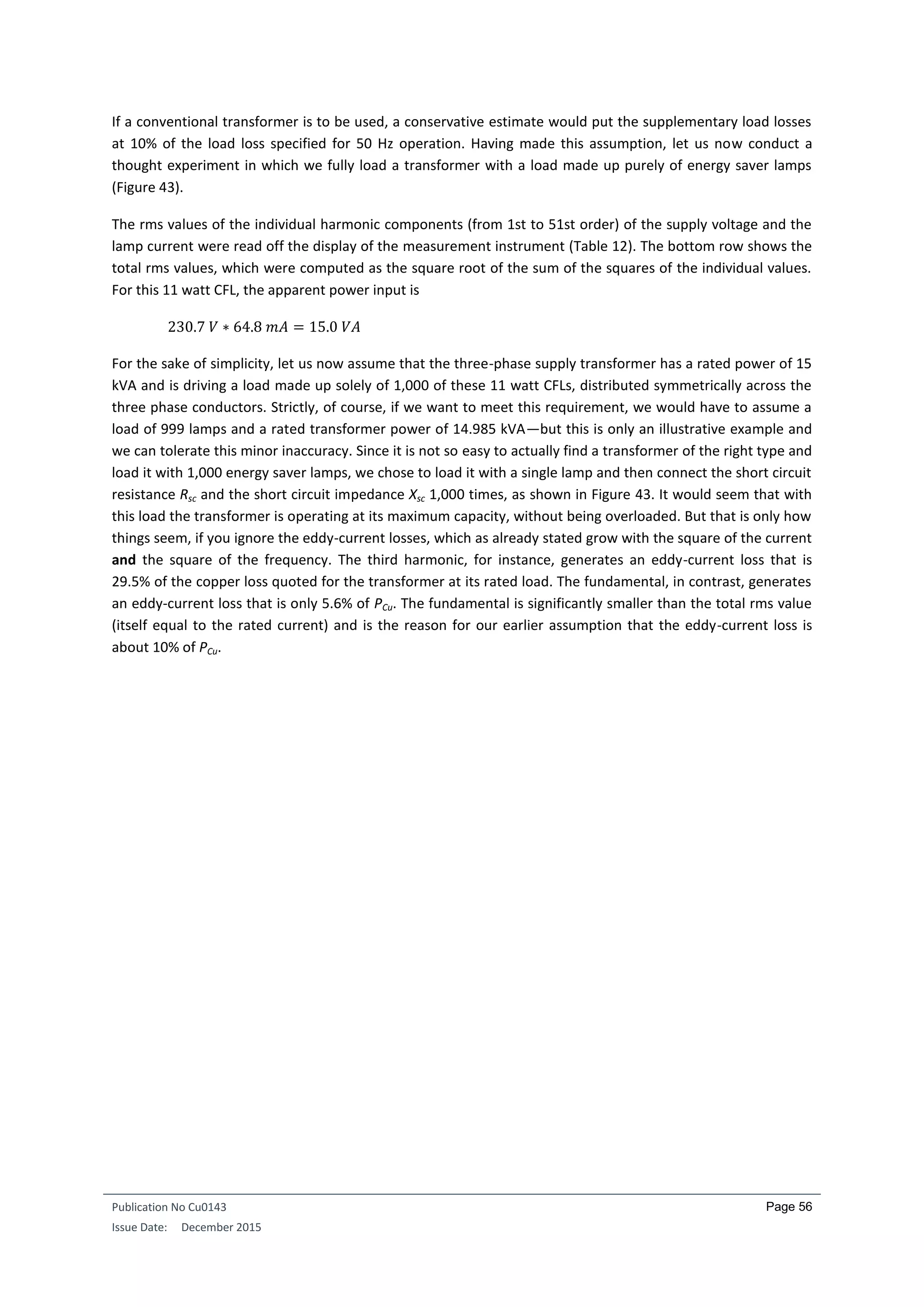
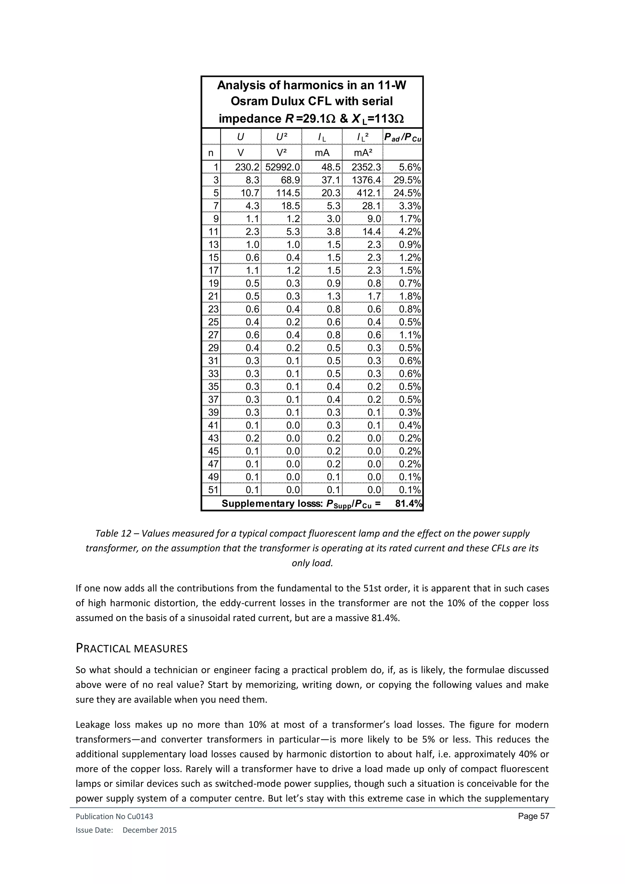
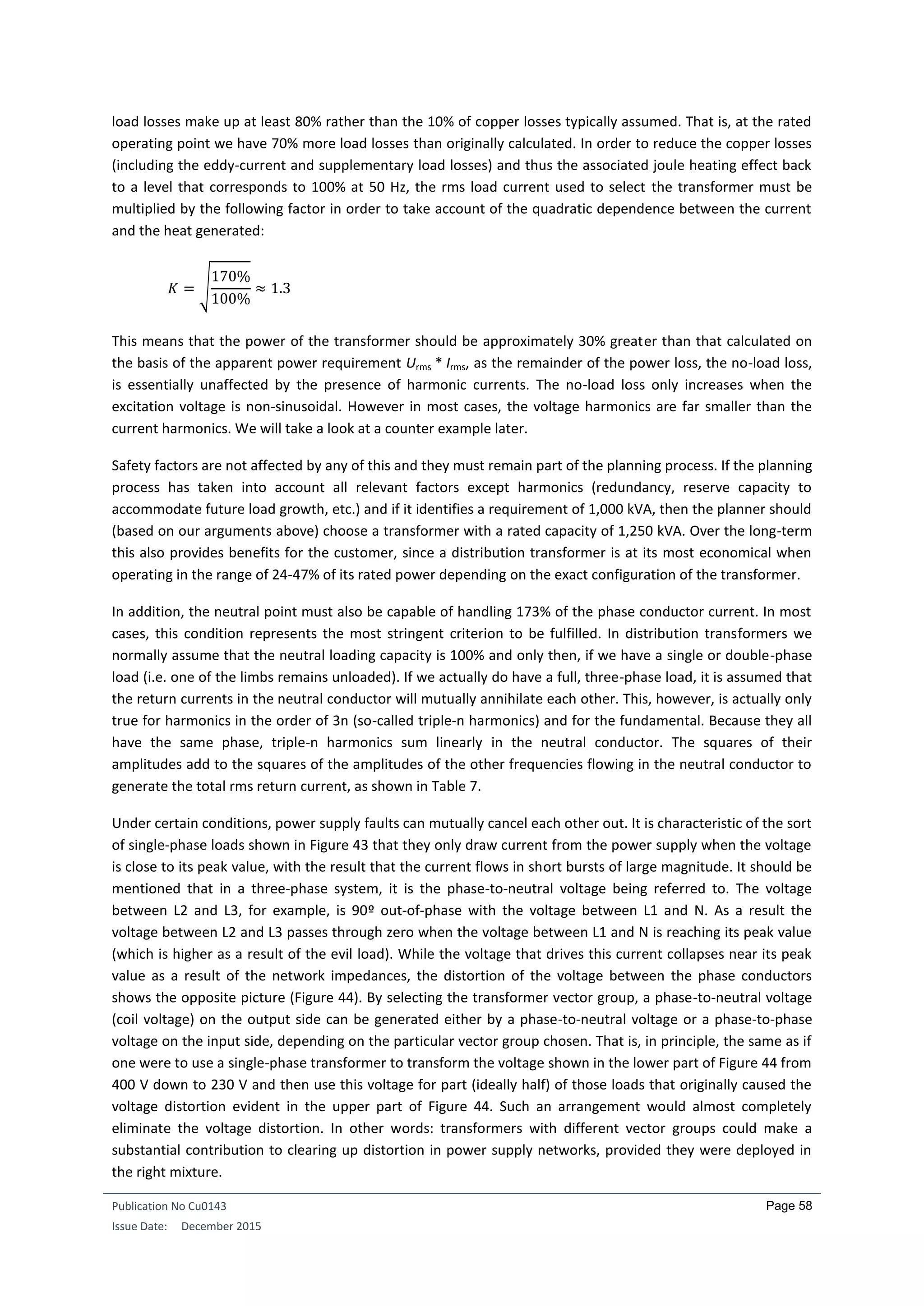
INTRODUCTION: WHY DO WE NEED A TRANSFORMER?
Why do we need a transformer? Electric power has to be transmitted at the highest feasible voltage if power
losses in the electricity line are to be kept within reasonable limits. This is true in absolute terms: the higher
the transmission voltage, the lower the current and hence the smaller the (resistive) power loss in the line. It is
also true in relative terms. While a 3 V voltage drop in a motor vehicle’s 12-volt on-board electrical system is a
significant loss, it would hardly be noticed in a 230 /400 V distribution network and certainly would not impair
the function of any load. In a high voltage network, the same 3-volt drop would be almost immeasurably small.
Consider a transformer of certain dimensions. Now double each of the three dimensions: length, width, and
height, while retaining the same transformer structure. Clearly, the area of any face of the transformer will
increase fourfold. This will also apply to those surfaces available for dissipating heat losses, to the cross-
sectional area of the conductors, and to the cross-sectional area of the iron core—each of which is an
important transformer design parameter. If the linear dimensions are doubled however, all volumes will
increase by a factor of eight and so will the corresponding mass.
Assuming that the current densities in the conductors remain unchanged, the current carrying capacity (or
ampacity) of the conductors will increase fourfold, since the cross-sectional area of the conductors is now four
times as great. The current density measured in all transformers rated from 10 VA to 1 GVA is indeed
approximately 3 A/mm² for copper conductors and about 2 A/mm² when the conductor material is aluminium.
However, doubling the dimensions of the wire not only increases the conductor’s cross-section by a factor
four, it also doubles its length. The eightfold increase in the volume of the conductor material mentioned
above corresponds to an eightfold increase in the mass of copper or aluminium used. For a given current
density and temperature (though the effect of temperature is not critical in this simple analysis), every
kilogram of a particular conductor material will generate the same amount of heat loss. Therefore, a
transformer whose length, width, and height have all been doubled will weigh eight times as much, and the
heat losses it generates will consequently also rise by a factor of eight. This eightfold increase in heat loss must
nevertheless be dissipated by cooling surfaces whose area is only four times as great—a fact that we ignored
above. In practical applications, larger transformers therefore need additional cooling. The first step is to
introduce liquid cooling of the transformer windings. Further cooling can be achieved by increasing the area of
the transformer cooling surfaces. This type of cooling system is known as ONAN cooling (oil natural circulation,
air natural circulation). Forced cooling is used in transformers with ratings above about 40 MVA. In this type of
cooling, known as ONAF cooling (oil natural circulation, air forced circulation), liquid cooling is augmented by
cool air blown in by fans. Above about 400 MVA, it becomes necessary to use pumps to help circulate the oil
coolant. This form of cooling is abbreviated OFAF and stands for oil forced, air forced circulation. In
transformers with power ratings greater than 800 MVA, simply circulating the oil is no longer sufficient and
these transformers use ODAF cooling (oil directed, air forced cooling) in which a jet of cooling oil is directed
into the oil channels of the transformer windings.
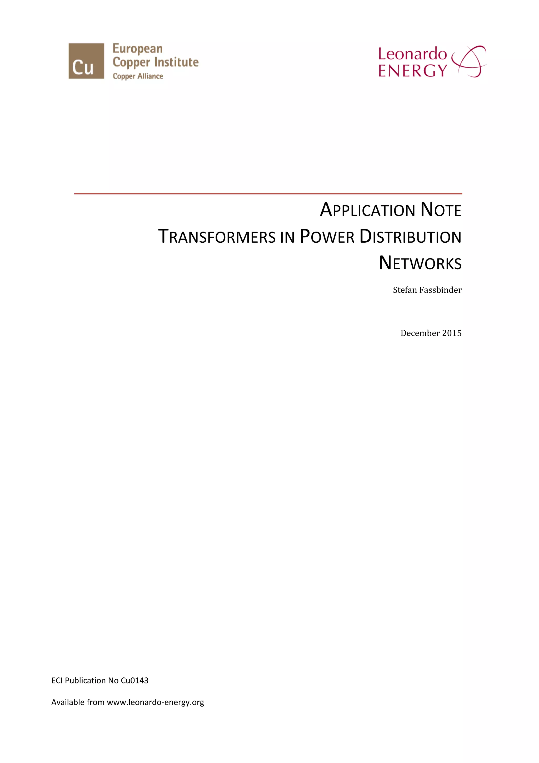
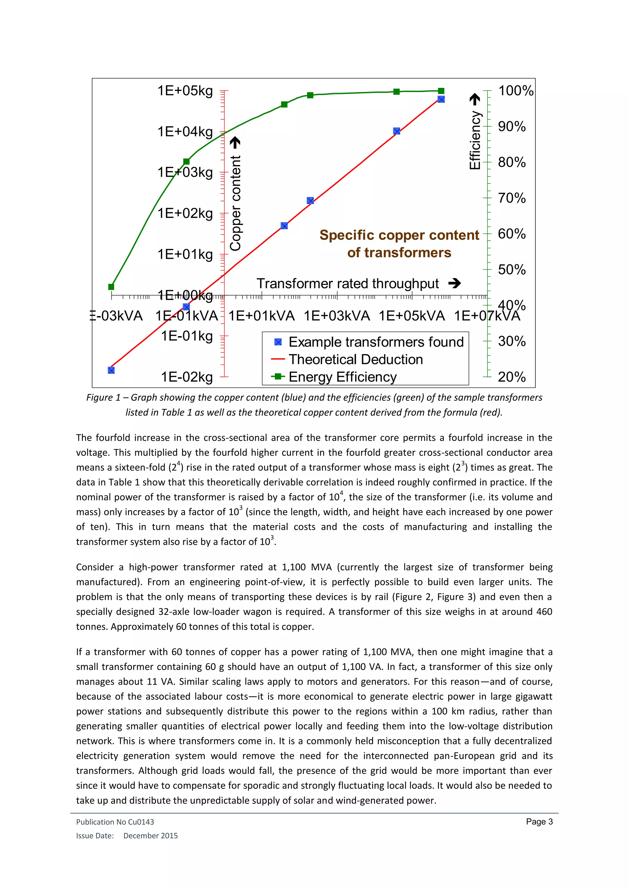
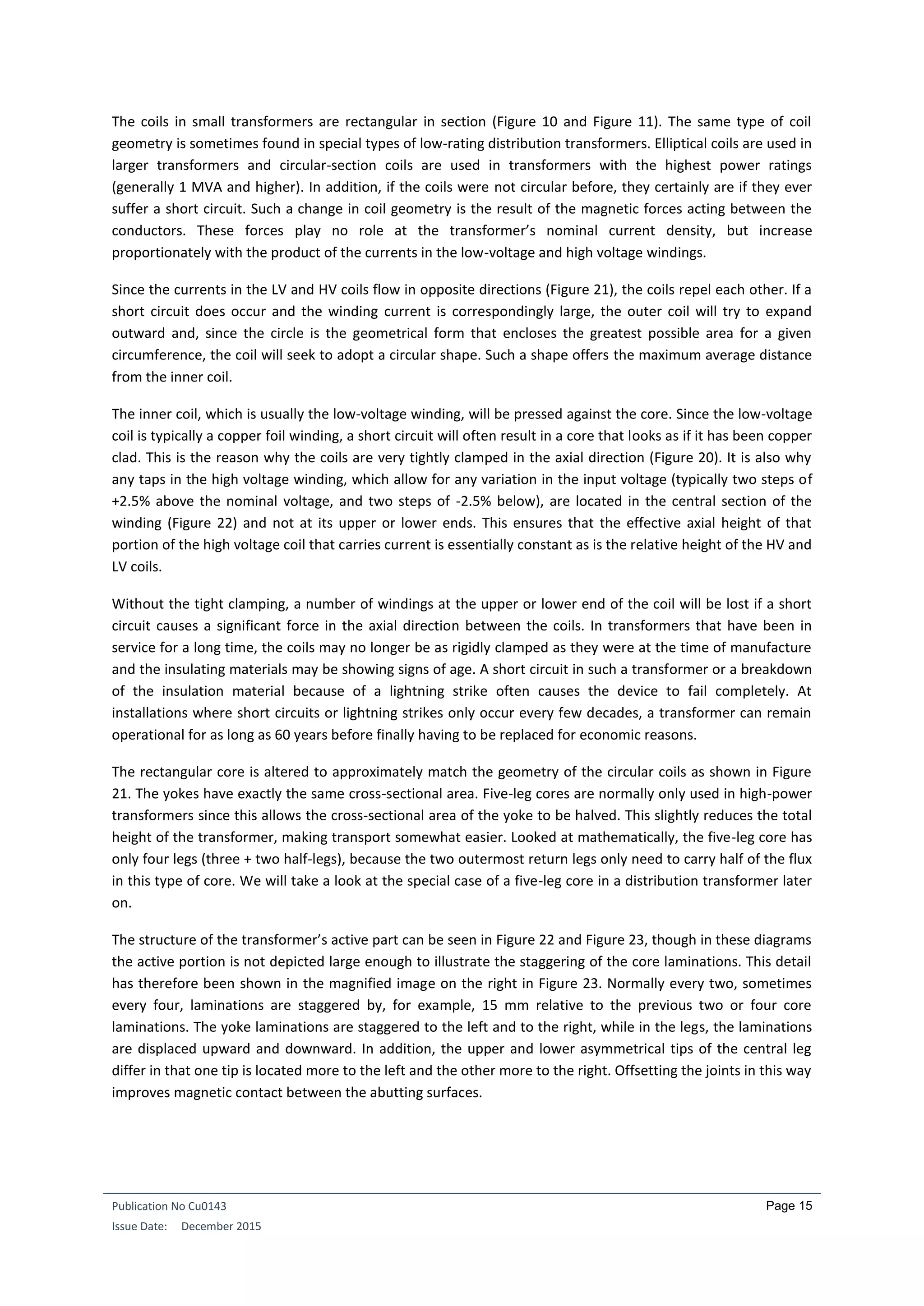
Table 1 – Power densities and efficiencies of a range of real transformers from a miniature transformer to a
generator transformer.
Example transformers
found
S [kVA] Cu [kg]
S/Cu
[kVA/kg]
S/Cu4/3
[kVA/kg4/3
]
Current
Density
[A/mm²]
Energy
Efficiency
Minimum Transformer 0.001 0.014 0.070 0.291 7.000 45.00%
Small Transformer 0.100 0.500 0.200 0.252 3.000 80.00%
Industrial Transformer 40.000 48.200 0.830 0.228 3.397 96.00%
Distribution Transformer 200.000 200.000 1.000 0.171 98.50%
Bulk Supply Point Transformer 40000.000 10000.000 4.000 0.186 3.000 99.50%
Generator Transformer 600000.000 60000.000 10.000 0.255 99.75%
Geometric Mean Value --- --- --- 0.227 --- ---](https://image.slidesharecdn.com/cu0143-an-distributiontransformersv3-190429221715/75/Transformers-in-Power-Distribution-Networks-5-2048.jpg)
![Publication No Cu0143
Issue Date: December 2015
Page 19
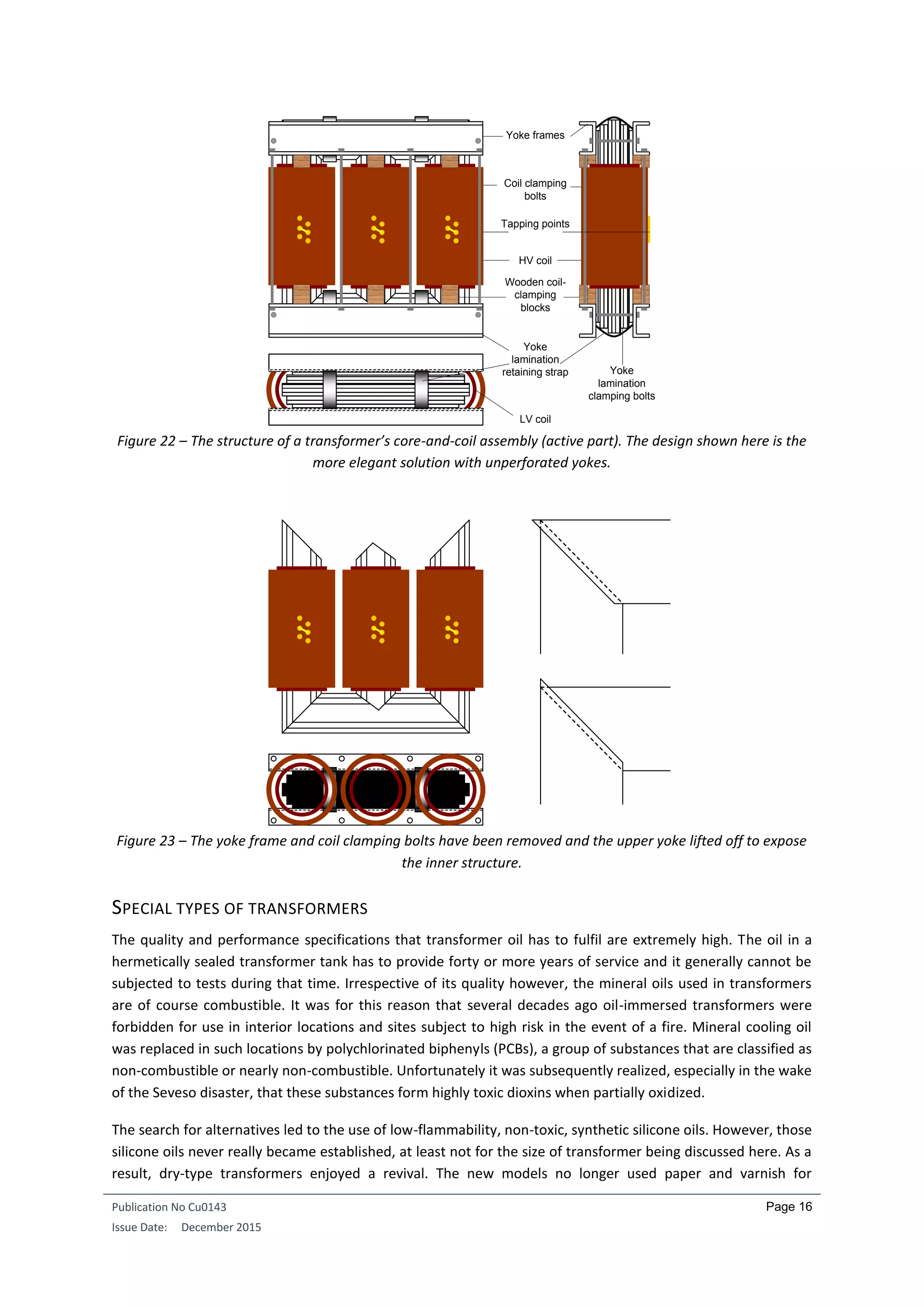
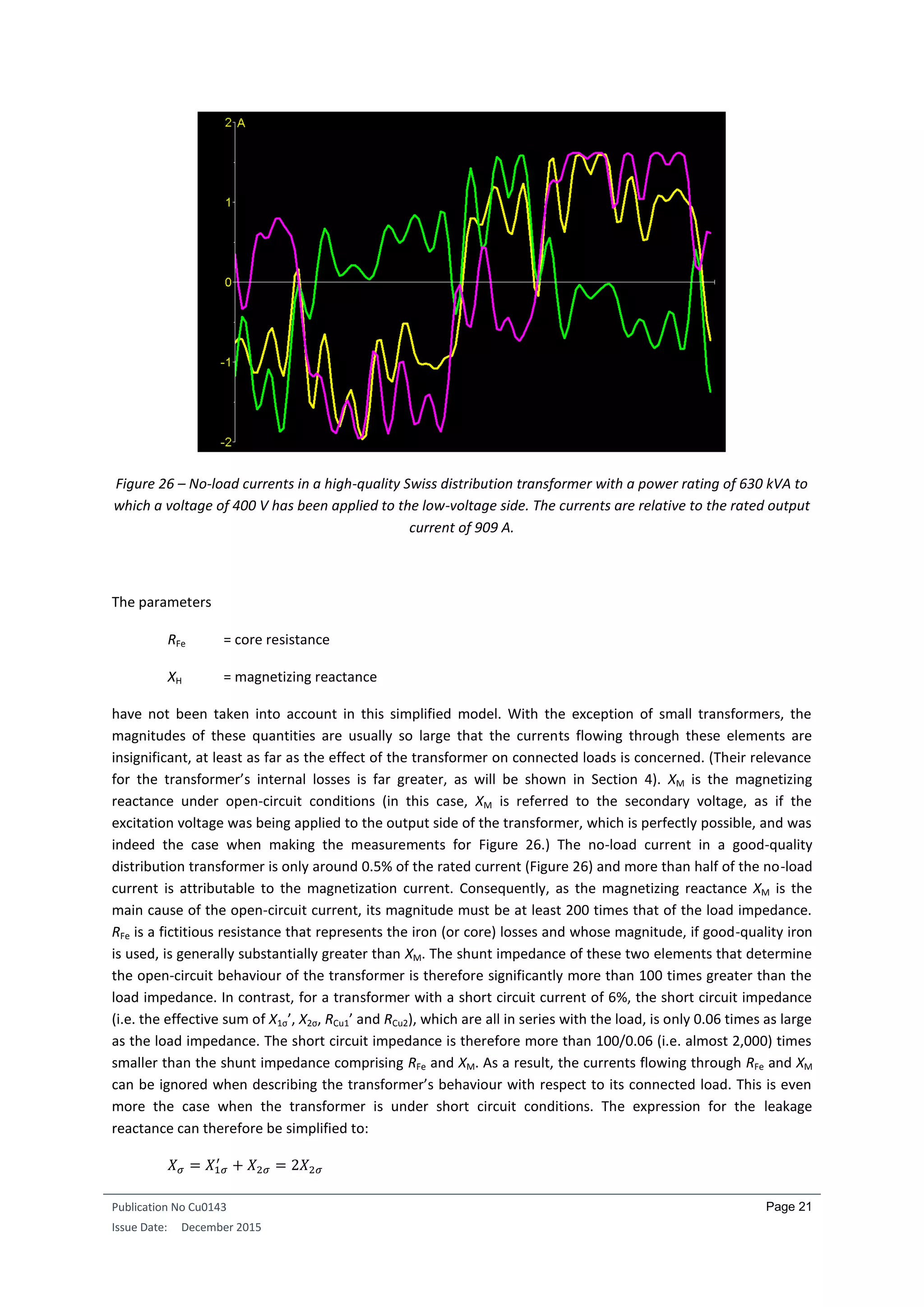
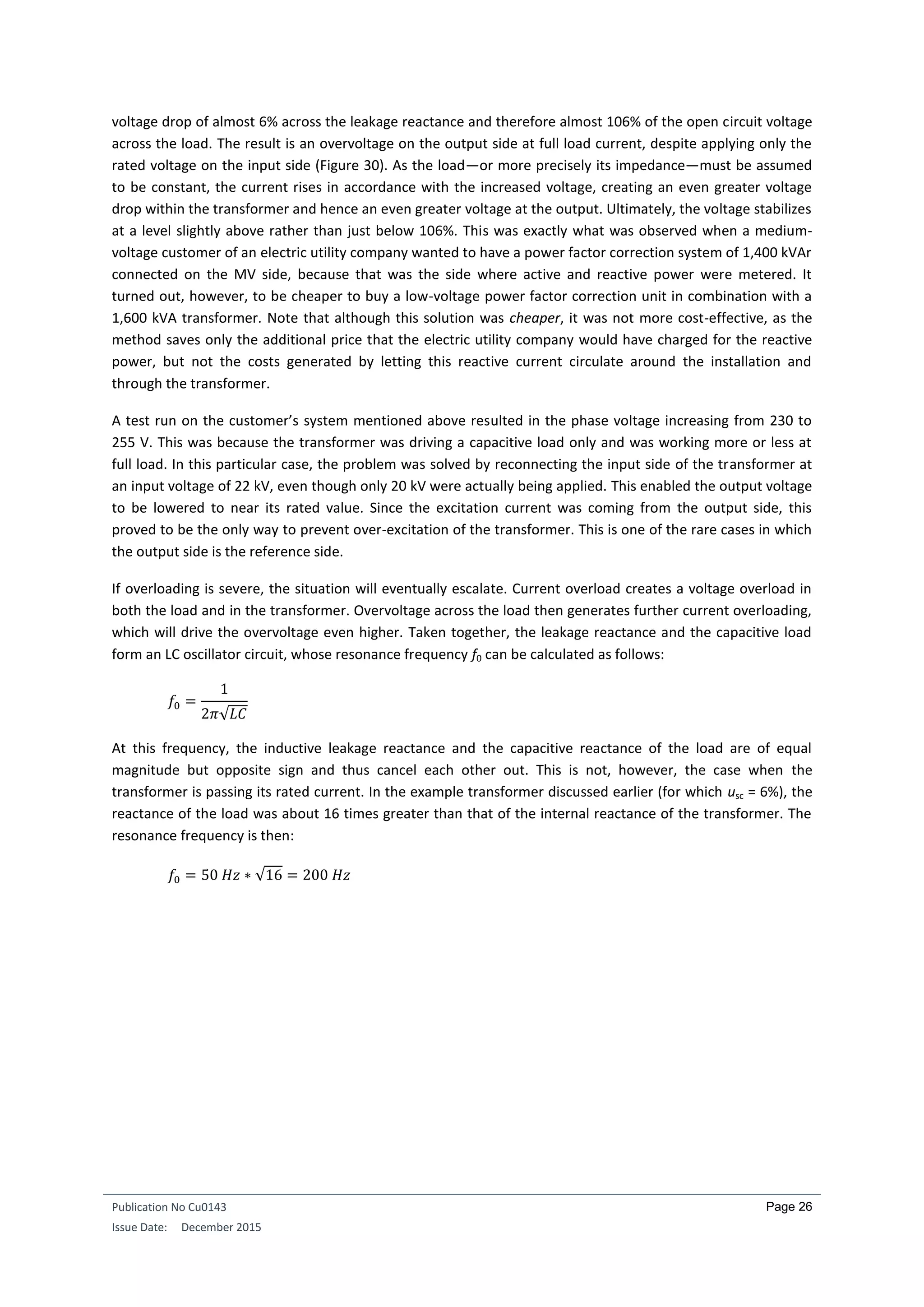
The short circuit voltage thus characterizes the voltage drop within the transformer. If the short circuit voltage
is known, the short circuit current Isc can be readily calculated. For example, if all upstream impedances are
ignored, the short circuit current in a transformer with usc = 6% is:
𝐼𝑆𝐶 =
𝐼 𝑁
𝑢 𝑠𝑐
=
𝐼 𝑁
6%
≈ 16.7 𝐼 𝑁
For a transformer with usc = 6%, six percent of the rated input voltage is therefore needed to generate the
rated (nominal) current IN in the short-circuited secondary winding. However, only a small part (uR) of the
voltage drop in a medium-sized distribution transformer is due to the ohmic resistances in the windings. The
largest factor contributing to the voltage drop is by far the reactive/inductive voltage drop uX. This stems from
the leakage inductance caused by the portion of the magnetic flux that bypasses the core (leakage flux) and
permeates only a single winding. This leakage flux does not flow in the primary and secondary windings
simultaneously. Rather it flows in the main leakage channel between the high voltage winding, which is
generally located on the outside, and the low-voltage winding on the inside [c.f. Section 2 Design]. The leakage
flux is therefore part of the magnetic flux of the outer but not the inner winding. This also has the incidental
effect that the short circuit voltage cannot be influenced by the non-linearity of the iron core. uX is also
referred to as the leakage reactance voltage. The principal function of the main leakage channel is cooling; its
secondary function is insulation. In addition, it also serves to maintain the so-called leakage reactance, which is
in effect a defined short circuit voltage.
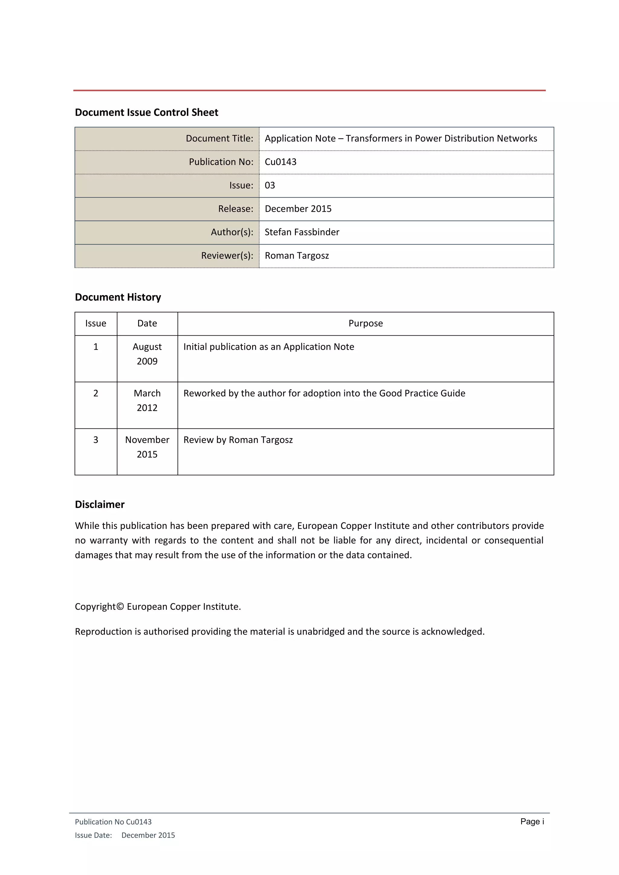
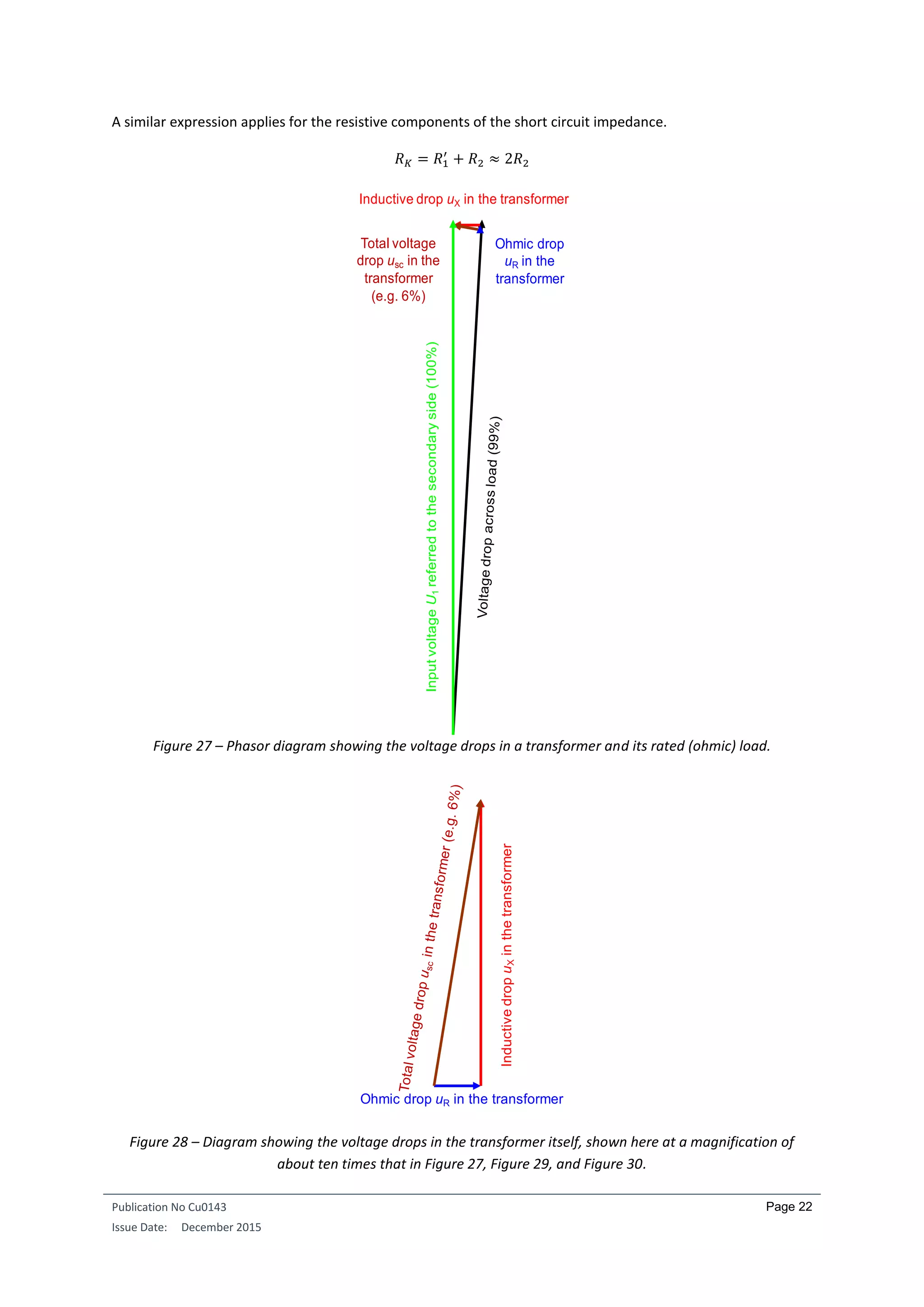
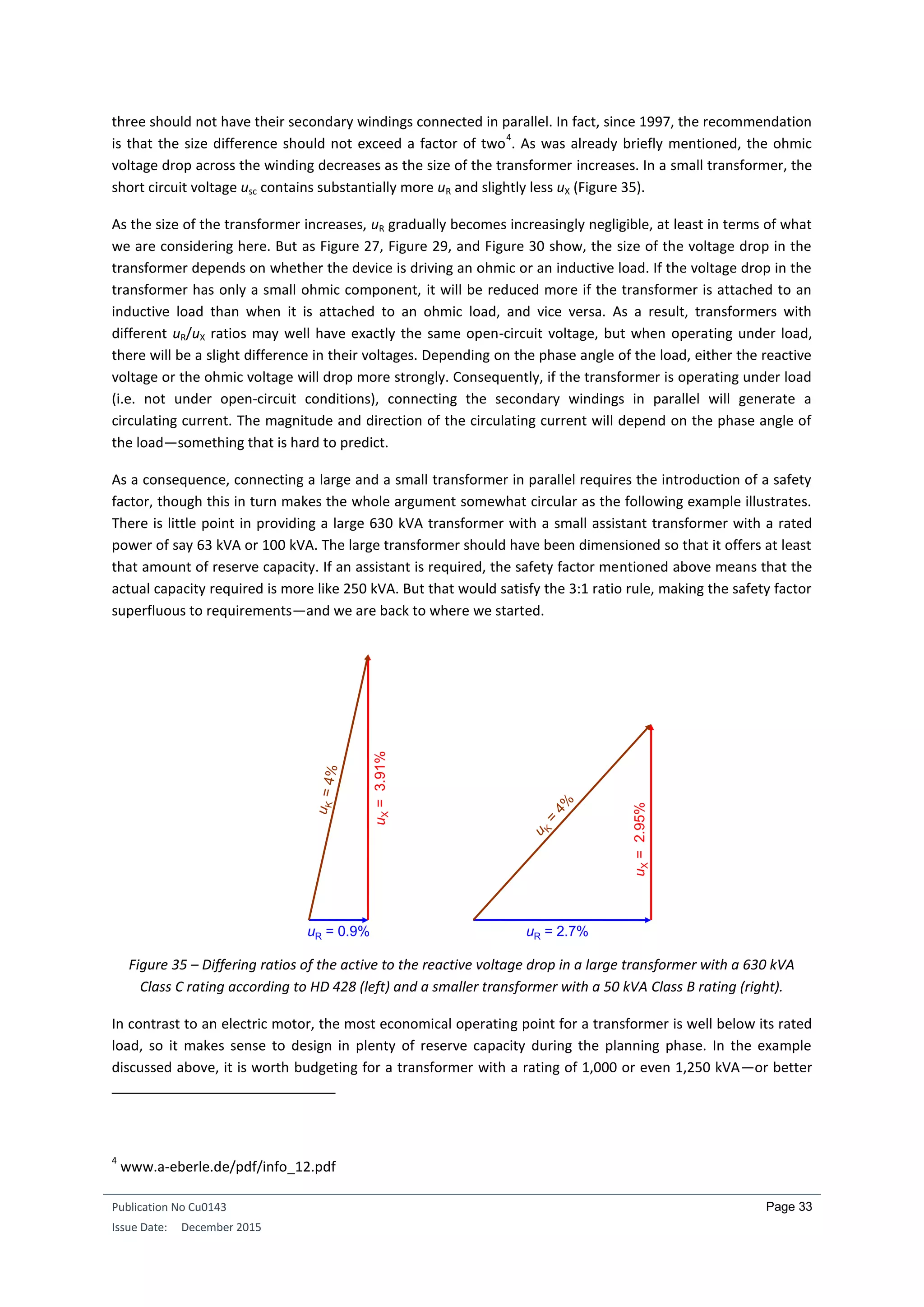
As shown in Figure 28, the sum of the squares of the inductive voltage drop uX and the ohmic voltage drop uR
equals the square of the overall voltage drop usc (c.f. Pythagoras’ theorem concerning the sides of a right-
angled triangle). Fortunately, the ohmic voltage drop uR is, as already mentioned, the smaller portion. The
larger the transformer, the smaller this is. A simple calculation proves this point: If a transformer in the 630
kVA range has an efficiency of 98.5% when operating at its rated load, then the total ohmic voltage drop across
the two windings can be no more than 1.5% of the rated voltage. In practice however, the value is lower, for
example 1%, because the 1.5% includes losses other than the ohmic losses in the coils. Our usc of 6% is
therefore made up of uR = 1% and uX = 5.91% of the rated voltage (6² =1² + 5.91²).
RESISTIVE LOAD
A transformer’s power rating is always specified relative to its resistive load. The ohmic resistance of the
winding contributes linearly to the (rated) load, while the inductive resistance (reactance) of the leakage
inductance contributes quadratically. Therefore the resistance of the winding contributes only 1% to the load
resistance, with the remaining 5.91% having only a negligible effect on the total voltage drop across the
transformer and the load. We now want to determine precisely how small this effect actually is.
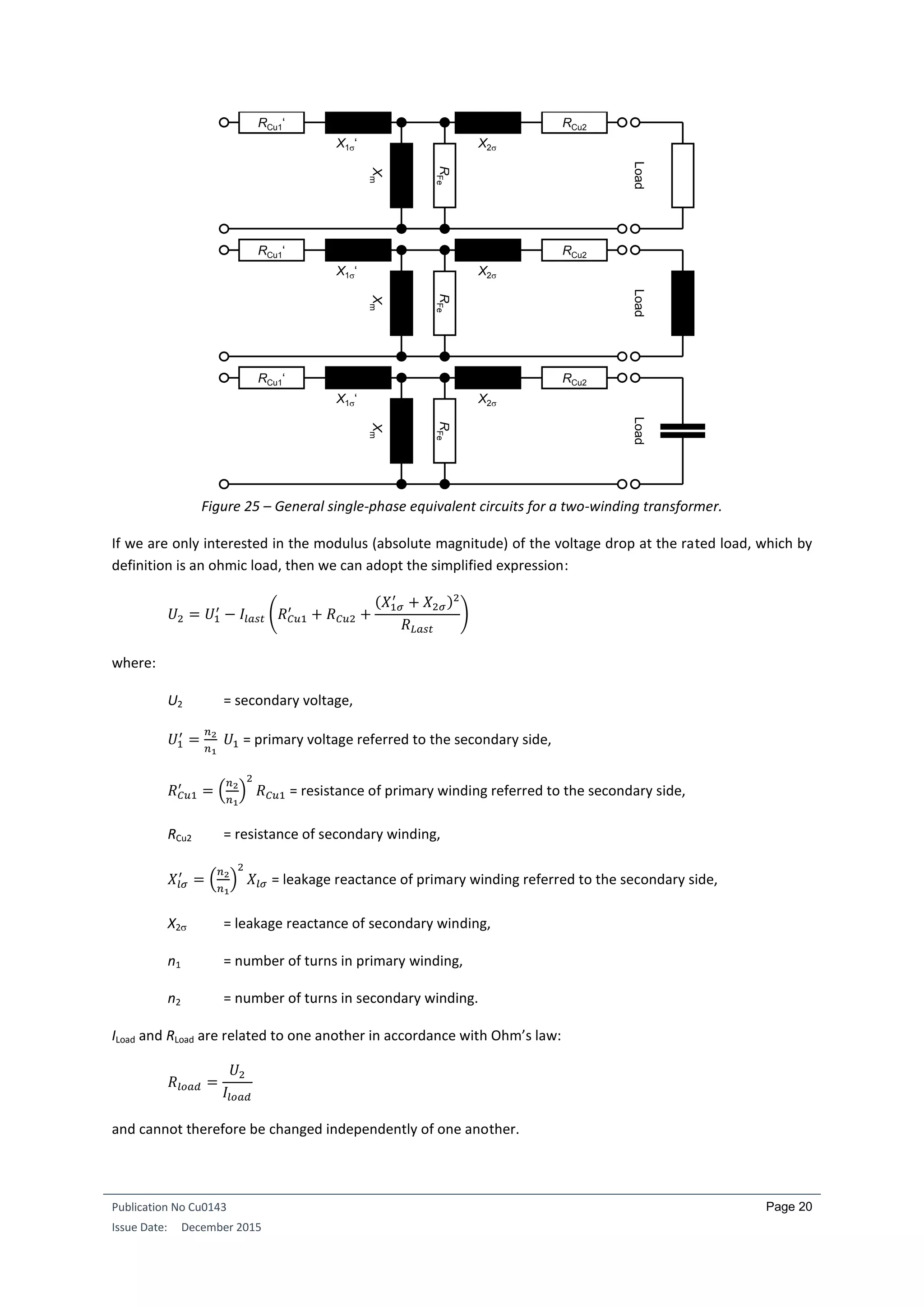
The non-ideal behaviour of a transformer can be illustrated by an equivalent circuit model (Figure 25). The
model assumes that the input and output windings have the same number of turns. As this is obviously not
usually the case, the values associated with one side of the transformer are moved (i.e. referred) to the other
side by multiplying them by the ratio of the number of turns on the two windings. The behaviour of the
transformer can then be calculated for the relevant reference side. In Figure 25, all elements have been
referenced to the load (i.e. secondary) side.](https://image.slidesharecdn.com/cu0143-an-distributiontransformersv3-190429221715/75/Transformers-in-Power-Distribution-Networks-22-2048.jpg)
![Publication No Cu0143
Issue Date: December 2015
Page 25
lived for a time next to a building site where a tower crane has been operating (without power-factor
correction) will know exactly what this refers to
1
. Luckily, mobile units are now available that can be used to
counteract such flicker sources
2
.
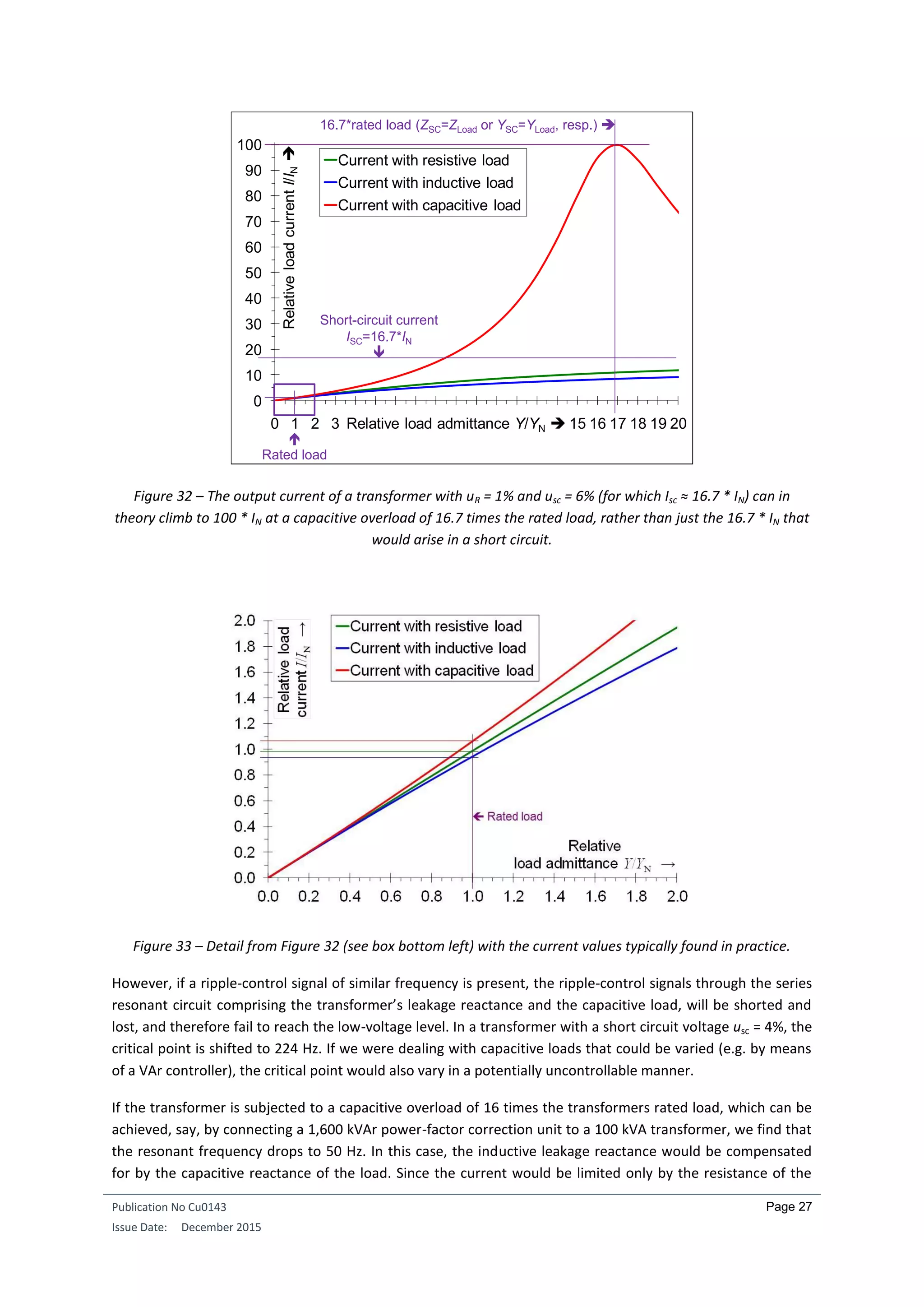
The same approach can be used to determine whether the primary cause of the voltage drop at a domestic
power socket is the leakage inductance of the distribution transformer or the ohmic resistance of the power
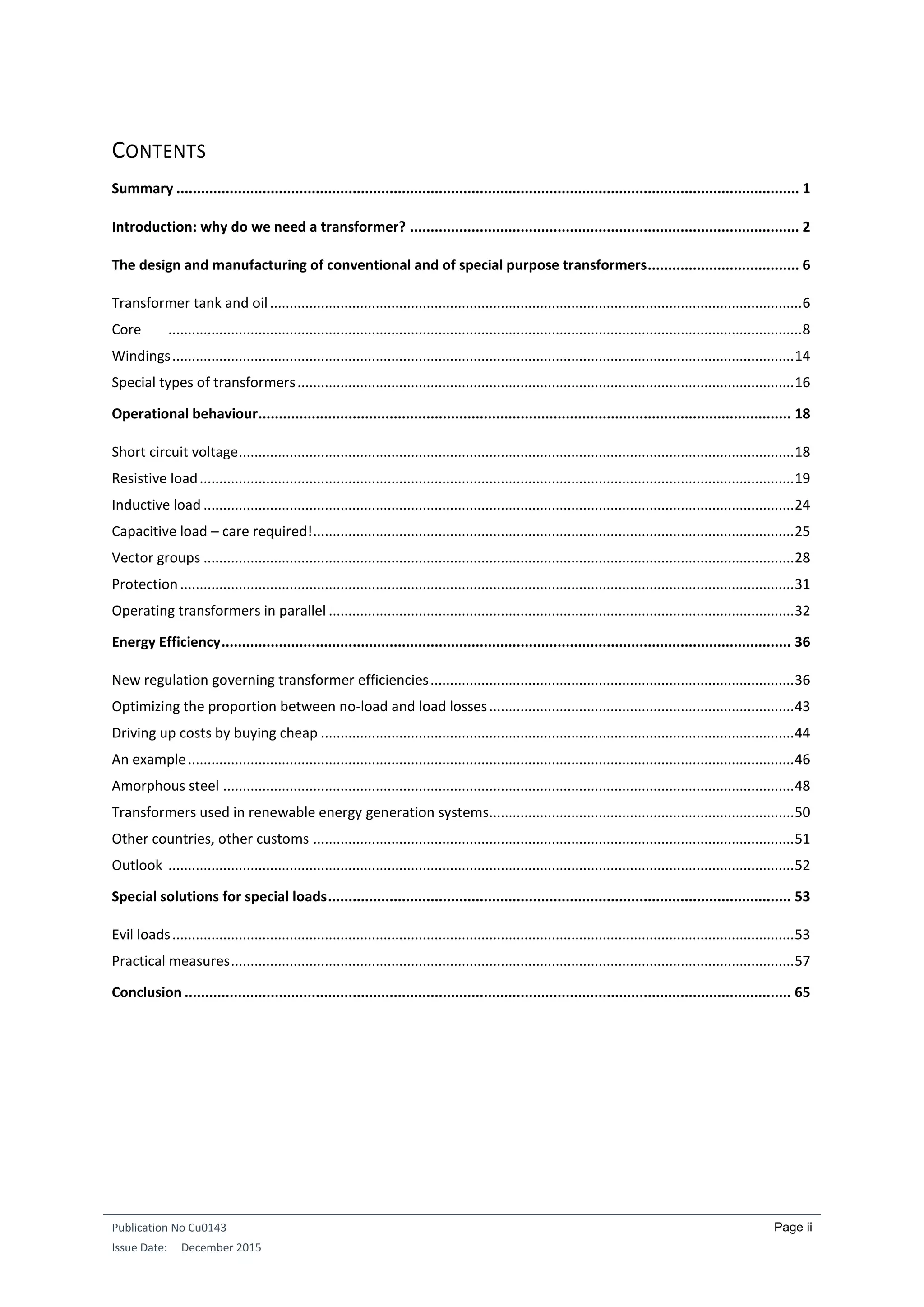
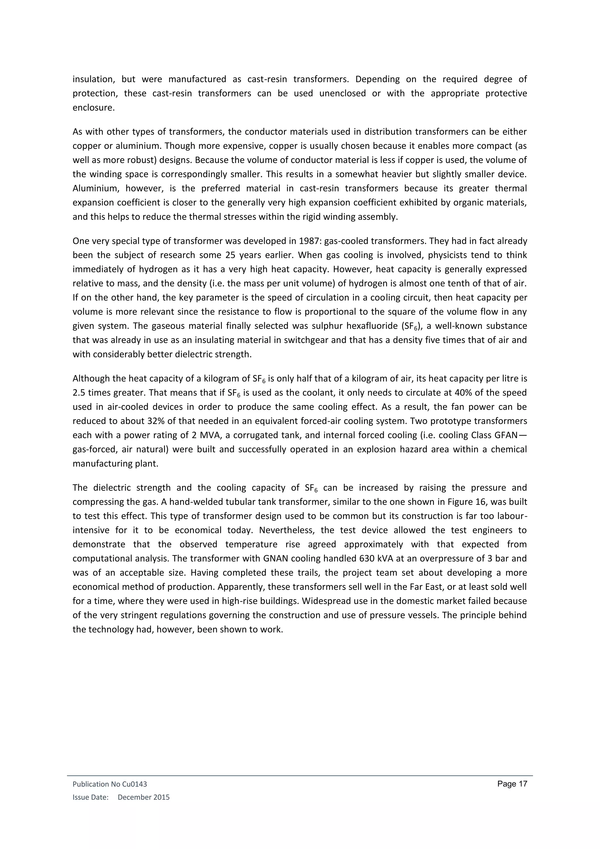
cables. For instance, when a fan heater with a current input of 9 A is operating, the voltage at a particular
power socket is found to decrease from 230.7 V to 226.3 V. If a large inductive load that draws over four times
as much current (see Figure 27) is connected, we see that there is no discernible increase in the voltage drop.
With reference to the phasor diagrams shown in Section 3.2, it can be concluded that the ohmic resistance is
by far the larger component—at least in the case of this particular cable and transformer. However, this test
must be performed with great caution. Since this test involves a substantial overload, the duration of the test
must be kept short. Failure to do this will trigger the 16-ampere circuit breaker, which is normally rated for a
power factor range from 1 to 0.6. A circuit breaker is not really the best means of switching off what is
essentially a purely inductive load.
Figure 31 – Large inductive load on a domestic power socket.
CAPACITIVE LOAD – CARE REQUIRED!
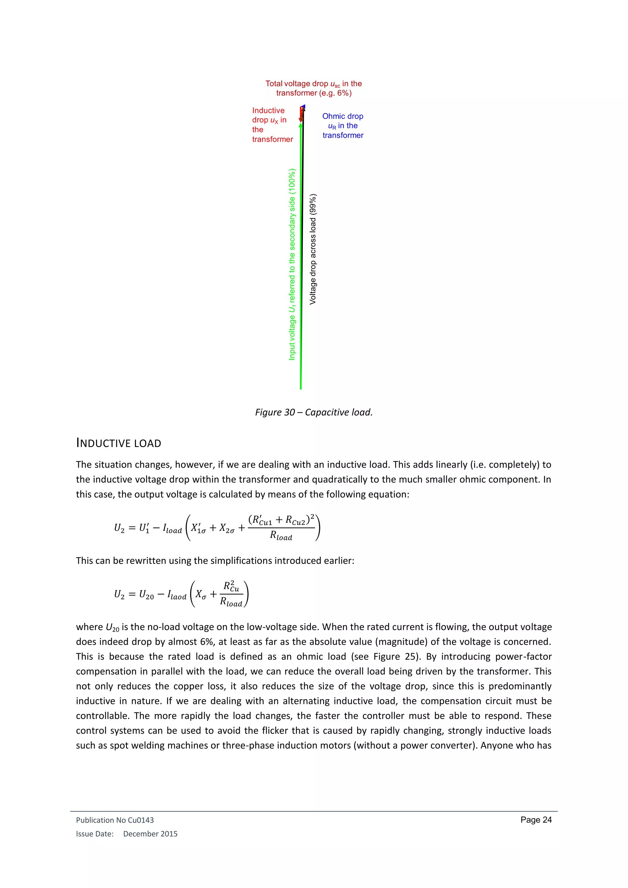
Things get really exciting when dealing with capacitive loads. In principle, this is the situation described earlier
in which the transformer is excited from the output side, i.e. compensation of the inductive magnetizing
reactive power by the capacitive load. If the load is so small that it is just sufficient to provide compensation,
then only the transformer will be excited—a perfectly normal situation, irrespective of the winding. The
picture changes however, as the capacitive load increases. The passage of the load current through the
leakage reactance results in a voltage drop with a phase lead of 90°. Its passage through the capacitive load is
accompanied by a voltage drop lagging by 90°. In other words, these two voltage drops have opposite signs
and therefore subtract from one another rather than add. At 100% of the rated input voltage, we have a
1
Fassbinder, Stefan: Netzstörungen durch passive und aktive Bauelemente, VDE Verlag, Berlin / Offenbach
2002, p. 188
2
Bolliger, R.: Wenn die Lichter flackern [‘When the lights flicker’]. ET Schweizer Zeitschrift für angewandte
Elektrotechnik 11/2003, p. 26](https://image.slidesharecdn.com/cu0143-an-distributiontransformersv3-190429221715/75/Transformers-in-Power-Distribution-Networks-28-2048.jpg)
![Publication No Cu0143
Issue Date: December 2015
Page 34
still—introducing system redundancy by including a pair of 630 kVA transformers, each of which is capable in
an emergency of handling the load on its own. Having reserve capacity also helps to settle the nerves. First,
conversion or retrofitting costs are far lower if there is a need to handle greater loads at some later date.
Secondly, power losses are reduced and, thirdly, the voltage drop in the transformer is lower as a result of
using either two 630 kVA devices in parallel or from using a single large device. Indeed this can be the
optimum solution for flicker problems since it gets things right at the start rather than attempting to deal with
the problem by grafting on a solution later
5
. Of course, the price for this improved resistance to flicker in the
supply system is a higher short circuit power. The short circuit power rises linearly with the size of the
transformer (provided the rated short circuit voltage is constant) and is the sum of the short circuit powers of
the individual transformers if they are connected in parallel. This needs to be considered when configuring the
downstream distribution network.
The term short circuit power needs to be used with care. According to the definition, the short circuit power is
calculated by multiplying the open-circuit (i.e. no-load) voltage by the short circuit current. The operating
states no-load and short circuit are however mutually exclusive. Short circuit power is a purely fictional
computational parameter, but never-the-less one that is useful in estimating what could happen in the event
of a short circuit.
There is one further and very obvious condition for operating transformers in parallel: the vector group codes
of the units to be connected in parallel must be the same. The important aspect here is that the digits
following the letter codes are identical. If they were not the same, one would end up connecting windings with
different phase relationships—a situation that is obviously unacceptable. For instance, two transformers with
the vector group codes Dd0 and YNyn0 can certainly be operated in parallel. But if the neutral point is loaded,
the single-phase or non-linear load will be borne by only one of the transformers, since the other does not
have a neutral point. This needs to be taken into consideration. Additionally, the short circuit voltages on the
rating plates refer to symmetric, linear, three-phase loads. If another type of load is connected, quite different
values will apply. The size of the deviation will then depend strongly on the vector groups involved
6
. By this
point, things can have begun to get quite confusing. Connecting transformers with different vector groups in
parallel is certainly not to be recommended, and should only really be seen as an emergency measure.
When we discuss operating transformers in parallel, we normally mean that the output sides are connected in
parallel, as the input sides are usually connected either directly or indirectly in parallel. It is possible, however,
that a distribution transformer is fed from different MV systems, which in turn are fed from the same HV
system but via HV transformers with differing vector group codes (and therefore having different phase
relationships). In this case, the sum of the vector group code digits for the HV transformer and the
downstream distribution transformer must be the same for each HV transformer so that the voltages at the
secondary windings have the same phase.
But as is so often the case, that’s not quite the whole truth. Vector group codes are not the only significant
elements. We also need to take the power transmission networks into account. The case capacitance (i.e. the
5
See [1], p. 51
6
Fender, Manfred: Vergleichende Untersuchungen der Netzrückwirkungen von Umrichtern mit Zwischenkreis
bei Beachtung realer industrieller Anschlußstrukturen [‘Comparative studies of the effects of converters with
intermediate circuits on power quality in real industrial installations], Ph.D. thesis, Wiesbaden 1997](https://image.slidesharecdn.com/cu0143-an-distributiontransformersv3-190429221715/75/Transformers-in-Power-Distribution-Networks-37-2048.jpg)
![Publication No Cu0143
Issue Date: December 2015
Page 35
capacitance per unit length)
7
of underground cable is very large, while its series inductance (i.e. inductance per
unit length) is rather small. In overhead power lines, on the other hand, the capacitance is smaller and the
inductance is greater. Phase relationships will therefore vary depending on the specific load conditions.
Let us assume that we have two distribution transformers that are connected in parallel on their output sides.
They have the same rated outputs, the same vector groups, the same short circuit voltages, the same output
voltages, and even approximately the same copper losses. In other words, they are ideally suited to be
operated in parallel. One of the transformers is fed via a relatively long underground MV cable, the other via a
relatively long overhead MV line. As we assume that the voltages supplied at the start of the two cables have
the same phase and the modulus of the impedance is similar for the two cables, it is reasonable to expect that
there will not be any appreciable imbalance in the distribution of the common load. However, the phases of
the voltages arriving at the input sides of the two parallel distribution transformers (i.e. at the ends of the MV
supply cables) can indeed be different. The phase relationships measured at the LV bushings are therefore also
different and if the bushings are connected in parallel, a circulating current will begin to flow and the two
transformers will appear to heat up even under open circuit (no-load) conditions. However this is not actually
the case since the transformers are not really under no-load conditions. In fact, they drive the circulating
current. The power losses are almost purely reactive in nature. The only exception is the ohmic losses in the
two transformers as well as in their connection cables on the high voltage and low-voltage sides as far as the
coupling points.
The underground cable also represents a substantial capacitive load for the HV feeder transformer and, as
already described, this can cause an increase in the output voltage (Figure 33). In contrast, the capacitance of
the overhead line is probably small enough to be compensated (at least at full load) by the leakage inductance
of the distribution transformer that is being fed. The voltages can therefore differ not only in terms of their
absolute magnitudes but also with respect to phase. The question of whether this difference could become
critical is something that has to be calculated for a wide range of load cases during the planning phase. That is
not as simple as it sounds, given the large number of transformer and supply system parameters that need to
be taken into account.
Summary: Conditions for operating transformers in parallel
Same voltage across the windings to be connected in parallel
Same rated short circuit voltages
Same vector group codes
Ensure supply networks have the same phase relations
If the transformers are not connected in parallel on the input side, ensure that the supply networks
have approximately the same short circuit power levels
Maximum size ratio of transformers operated in parallel: 3:1
7
Fassbinder, Stefan: ‘Erdkabel kontra Freileitung’ [‘Underground vs overhead power transmission cables’], in
de, vol. 9/2001, p. gig9, appears in DKI reprint s180 ‘Drehstrom, Gleichstrom, Supraleitung – Energie-
Übertragung heute und morgen’ [‘Three-phase AC, DC and superconducting systems – Power transmission now
and in the future’] from the German Copper Institute (DKI), Düsseldorf](https://image.slidesharecdn.com/cu0143-an-distributiontransformersv3-190429221715/75/Transformers-in-Power-Distribution-Networks-38-2048.jpg)
![Publication No Cu0143
Issue Date: December 2015
Page 36
ENERGY EFFICIENCY
In 1999, the Swiss journal Bulletin SEV/VSE
8
carried a cover story entitled Replacing old transformers pays off
9
.
The article showed that as a result of the significant improvements in the efficiency of modern transformers,
there are now sound economic reasons (in addition to important environmental arguments) why older
transformers should be decommissioned even when they are still functioning properly. In this section, we
explain how these efficiency improvements have been achieved and their current and future significance for
those responsible for purchasing and deploying transformers.
NEW REGULATION GOVERNING TRANSFORMER EFFICIENCIES
On July 1st 2015 the new European Regulation N 548/14
10
on power transformers entered into force. This was
a world premier of a regulation stipulating a minimum energy performance for large power transformers.
The regulation establishes eco-design requirements for power transformers with a minimum power rating of 1
kVA used in 50 Hz electricity transmission and distribution networks or for industrial applications. The
regulation indicates that transformers are strategic assets in the electrical networks, playing an important role
in achieving the ambitious energy efficiency targets set by most industrialized countries. Considering Europe
only, 16.7 TWh (corresponding to 3.7 megatons of CO2) will be saved in 2025 through the reduction of no-load
and load losses of transformers falling under this regulation.
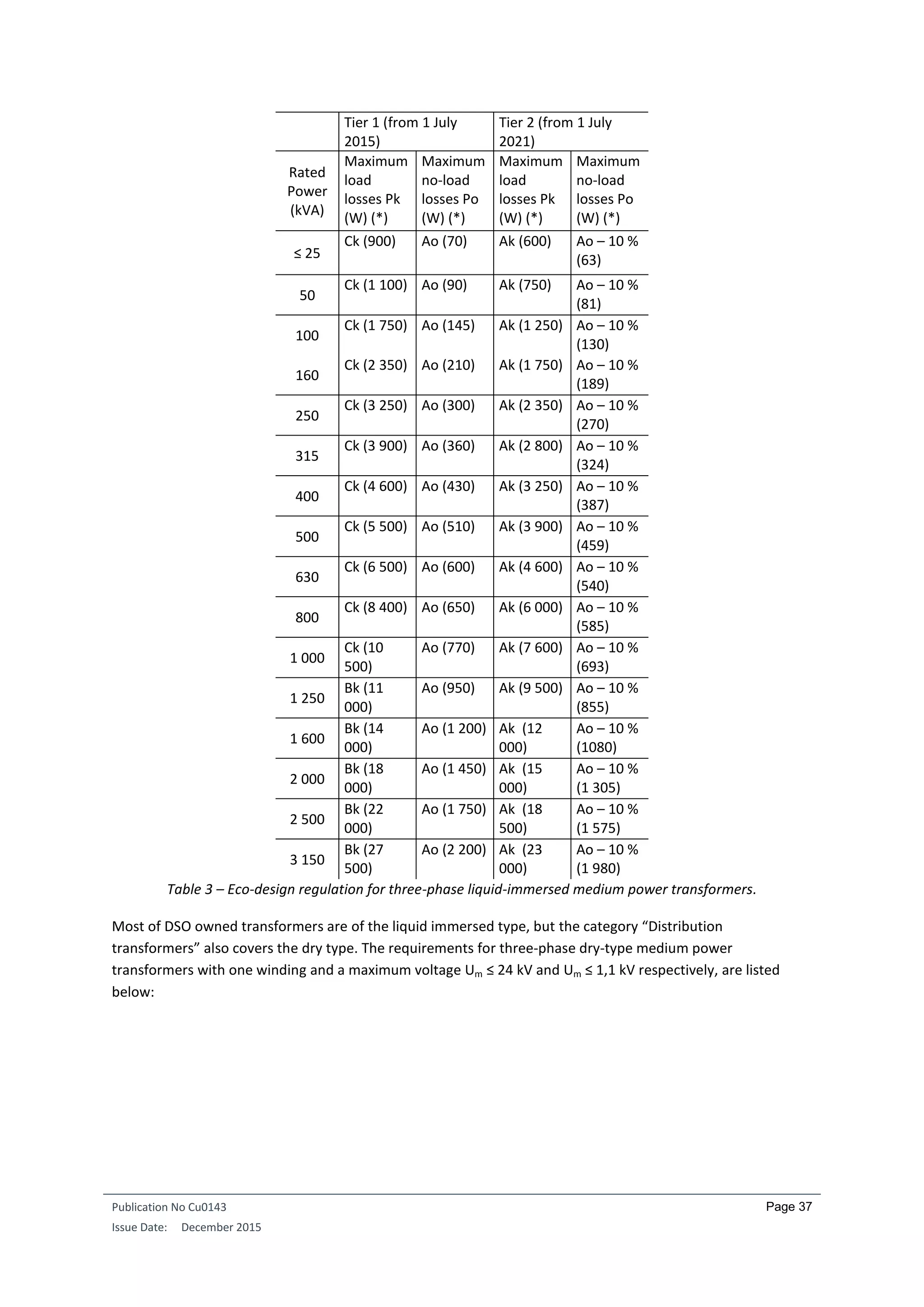
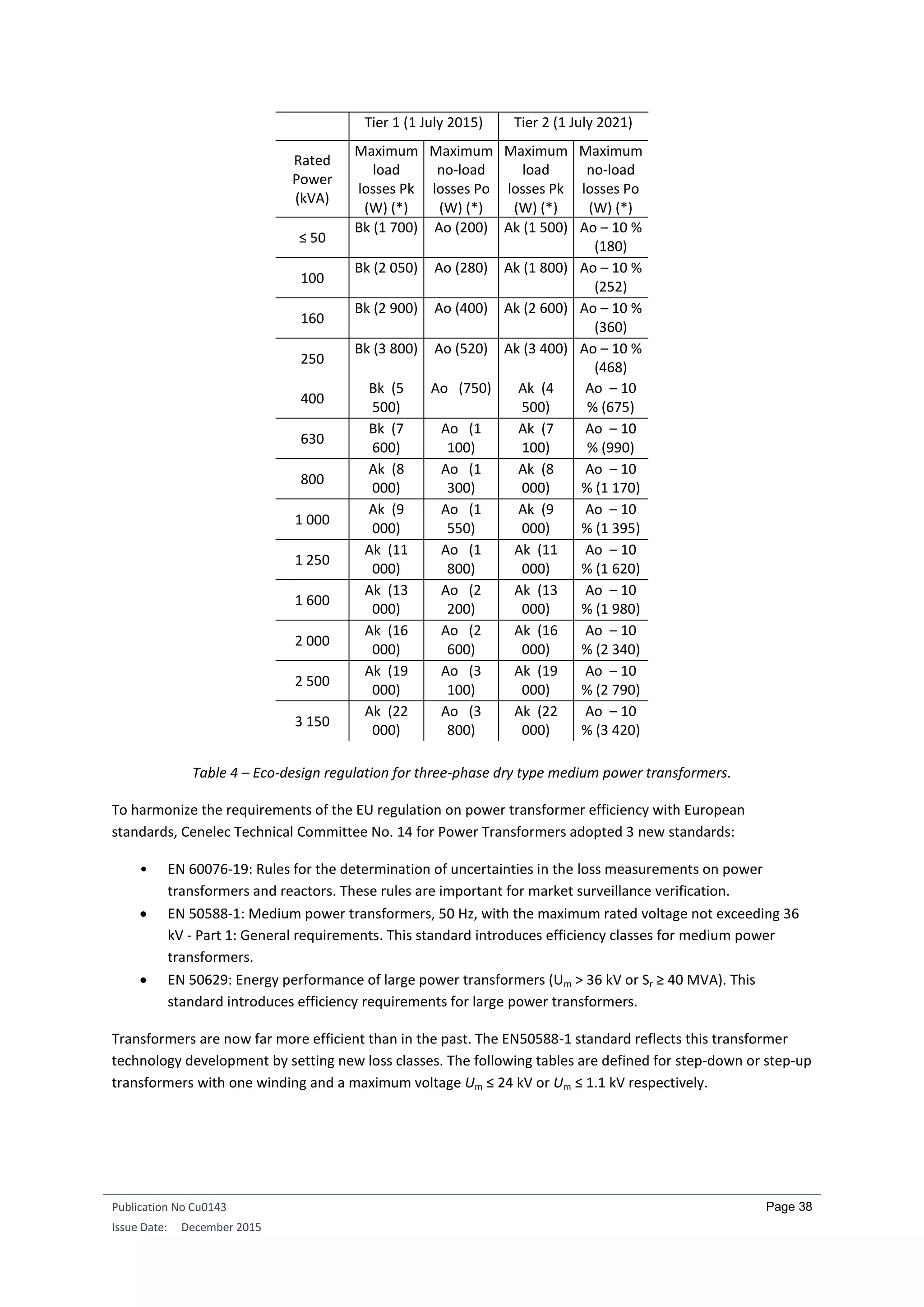
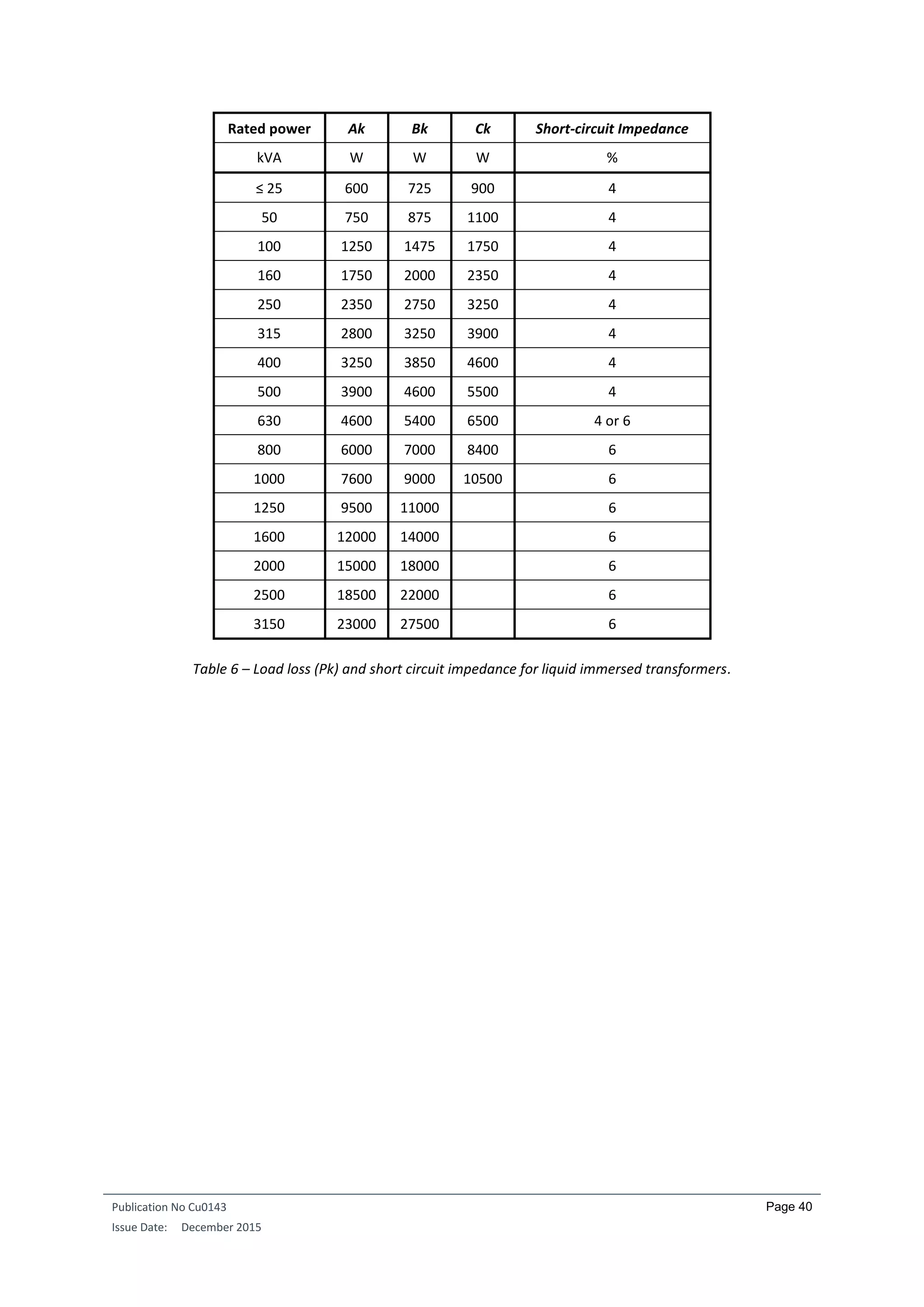
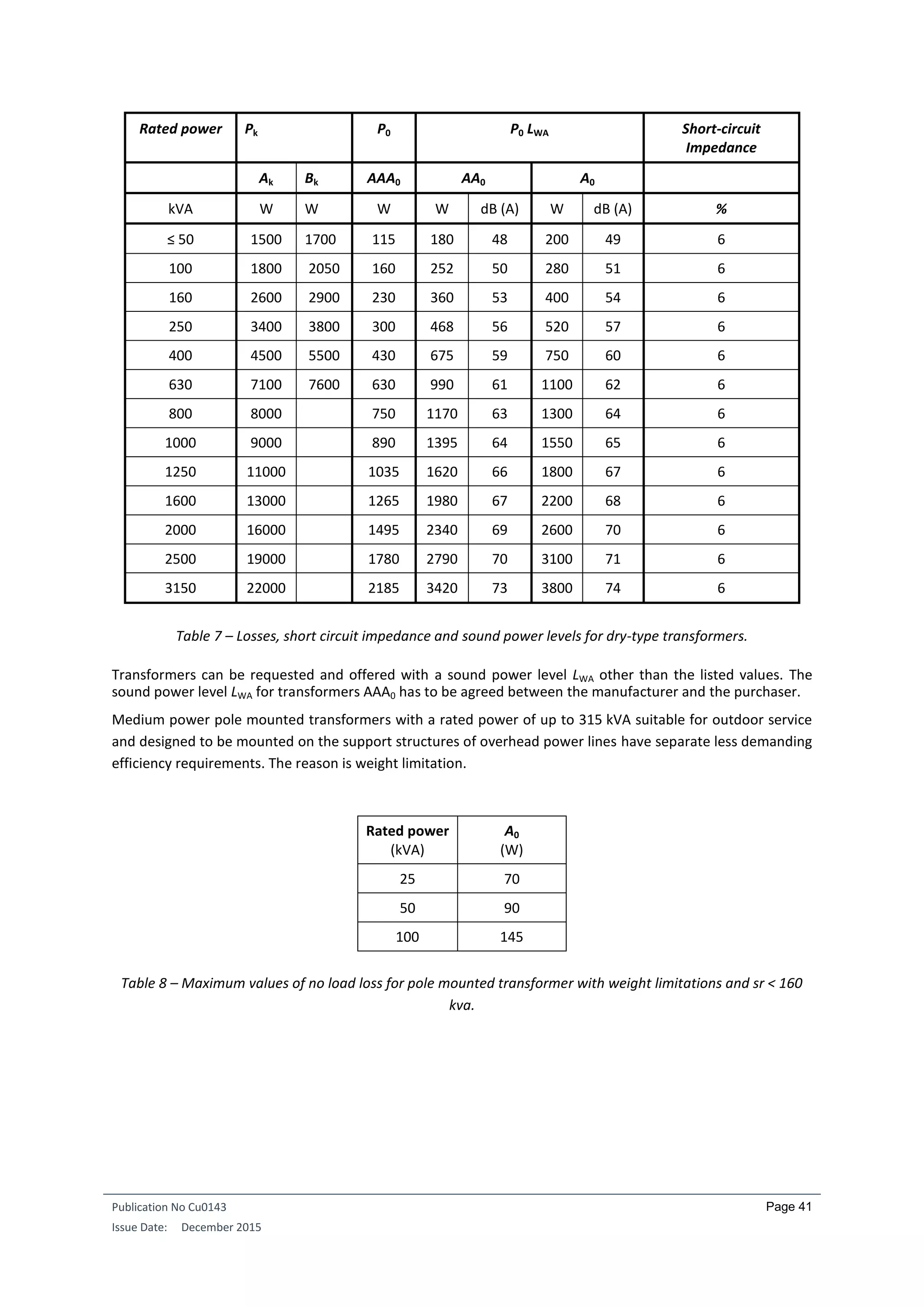
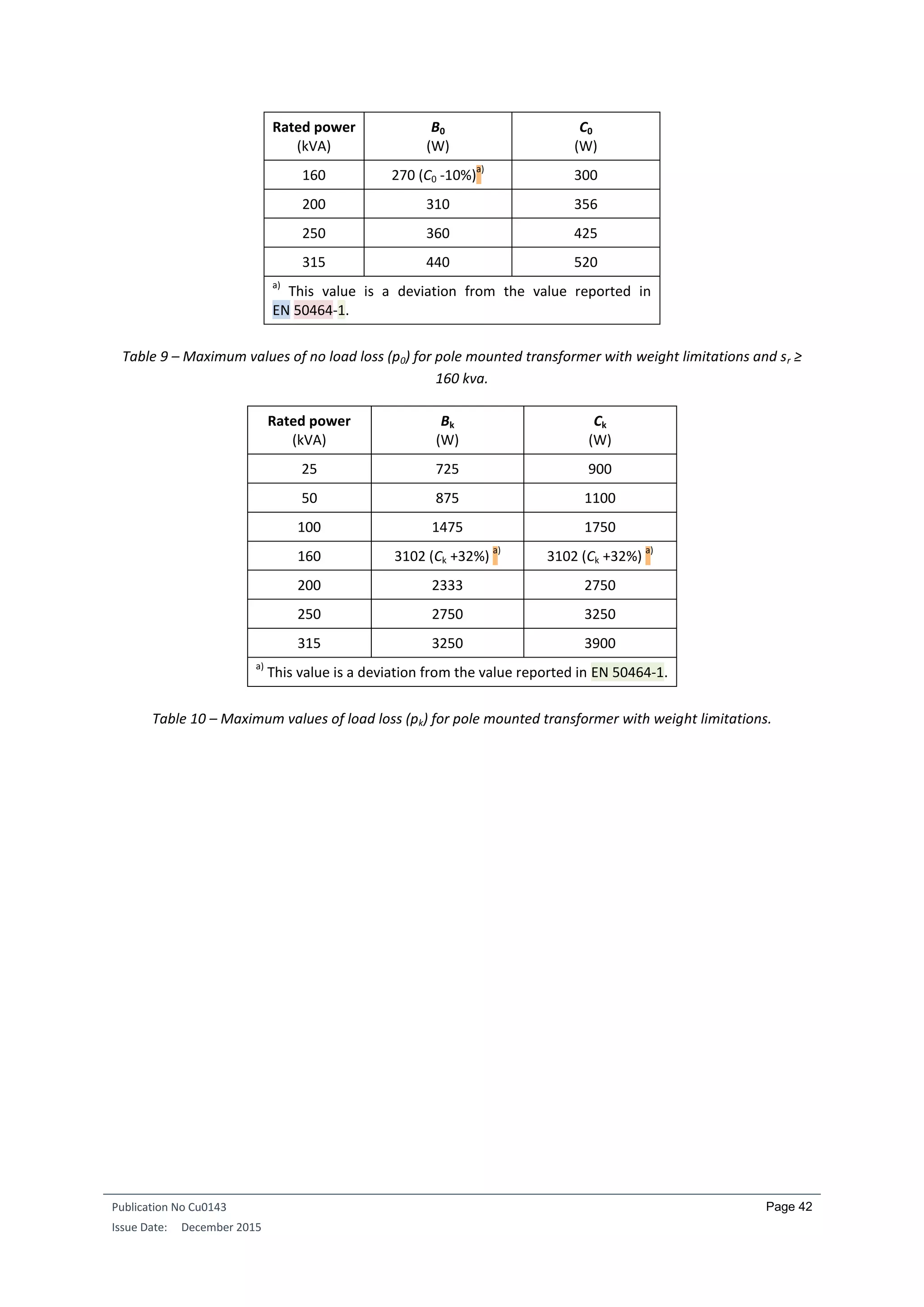
The requirements for distribution transformers are formulated in the form of maximum load and no-load
losses (in W).
Requirements for three-phase liquid-immersed medium power transformers with one winding are listed
below, for respectively Um (maximum voltage) ≤ 24 kV and for Um ≤ 1.1 kV:
8
SEV/Electrosuisse: Swiss Association for Electrical Engineering, Power and Information Technologies
VSE: Association of Swiss Electricity Utility Companies
9
Borer Edi: ‘Ersatz von Transformatoren-Veteranen macht sich bezahlt’ [‘Replacing old transformers does
pay’], in Bulletin SEV/VSE, vol. 4/1999, p. 31
10
http://eur-lex.europa.eu/legal-content/EN/TXT/PDF/?uri=OJ:L:2014:152:FULL&from=EN](https://image.slidesharecdn.com/cu0143-an-distributiontransformersv3-190429221715/75/Transformers-in-Power-Distribution-Networks-39-2048.jpg)
![Publication No Cu0143
Issue Date: December 2015
Page 45
higher, and the transformer generates correspondingly more heat in the electrical system to which it is
connected.
The best that can be said about this practice is that the transformer is a little smaller in size. But that is its sole
advantage and even that benefit can be lost because the higher temperatures generated mean that other
components have to be kept further away from it. Furthermore, the higher losses often require more effort
and expense to be spent on managing heat dissipation. The voltage drop is also larger. It is essential that
transformer professionals rid themselves of the ludicrous notion, which, when expressed provocatively, might
be phrased: ‘my transformer is better than yours, because it’s hotter.’ If progress means stepping up from
class H (with a continuous duty temperature rating of 180º C) to class C (220º C) then the heat really will be on.
How did this mind-set arise? Price pressure is the usual reason cited, with price meaning only the purchase
price and all follow-up costs conveniently ignored. But that would imply that market forces should have
eliminated any manufacturer offering more expensive devices. There are however a number of transformer
manufacturers who have decided to put quality first, and who are thriving as a result, despite the fact that the
first thing the customer is usually interested in is the price. The key here is to carefully explain to the customer
why the coil former is always fully wound, why these transformers are usually somewhat more expensive, and
occasionally significantly more expensive than apparently equivalent competitor products, and why using the
cheapest transformer usually leads to the most expensive system overall. The commercial success of these
companies
11
is clear proof that they are indeed managing to convince their clients that the purchase price of a
transformer is not its most important feature.
One manufacturer uses only grain-oriented sheet steel in the cores of all its transformers with a power rating
above about 1 kVA. This may well be due to the fact that the company uses some of these (auto)transformers
in one of its other business units to manufacture energy management units
12
as well as special DC link
converters. And an article on the latter reiterates what was said above about the danger of focusing only on
the price: ‘Over the last few years, cost and space considerations have led to an expansion of the thermal
insulation classes up to class H (180ºC)—a development that has brought with it numerous disadvantages…
13
’.
Apart from the fact that—strictly speaking—it should have read ‘…price and space considerations…’ (since
price and cost are not the same), the article underscores the company’s praiseworthy attitude regarding the
question of transformer efficiency.
11
www.riedel-trafobau.de, www.buerkle-schoeck.de
12
Decker, Christiane: ‘Energie sparen mit EMU’ [‘Saving energy with EMUs’], in de, vol. 15-16/2000, p. 34
13
Bürkle, Thomas: ‘Wassergekühlte Zweipunkt-Zwischenkreisdrosseln’ [‘Water-cooled two-point DC link
reactors’], in etz, vol. 22/2000, p. 18](https://image.slidesharecdn.com/cu0143-an-distributiontransformersv3-190429221715/75/Transformers-in-Power-Distribution-Networks-48-2048.jpg)
![Publication No Cu0143
Issue Date: December 2015
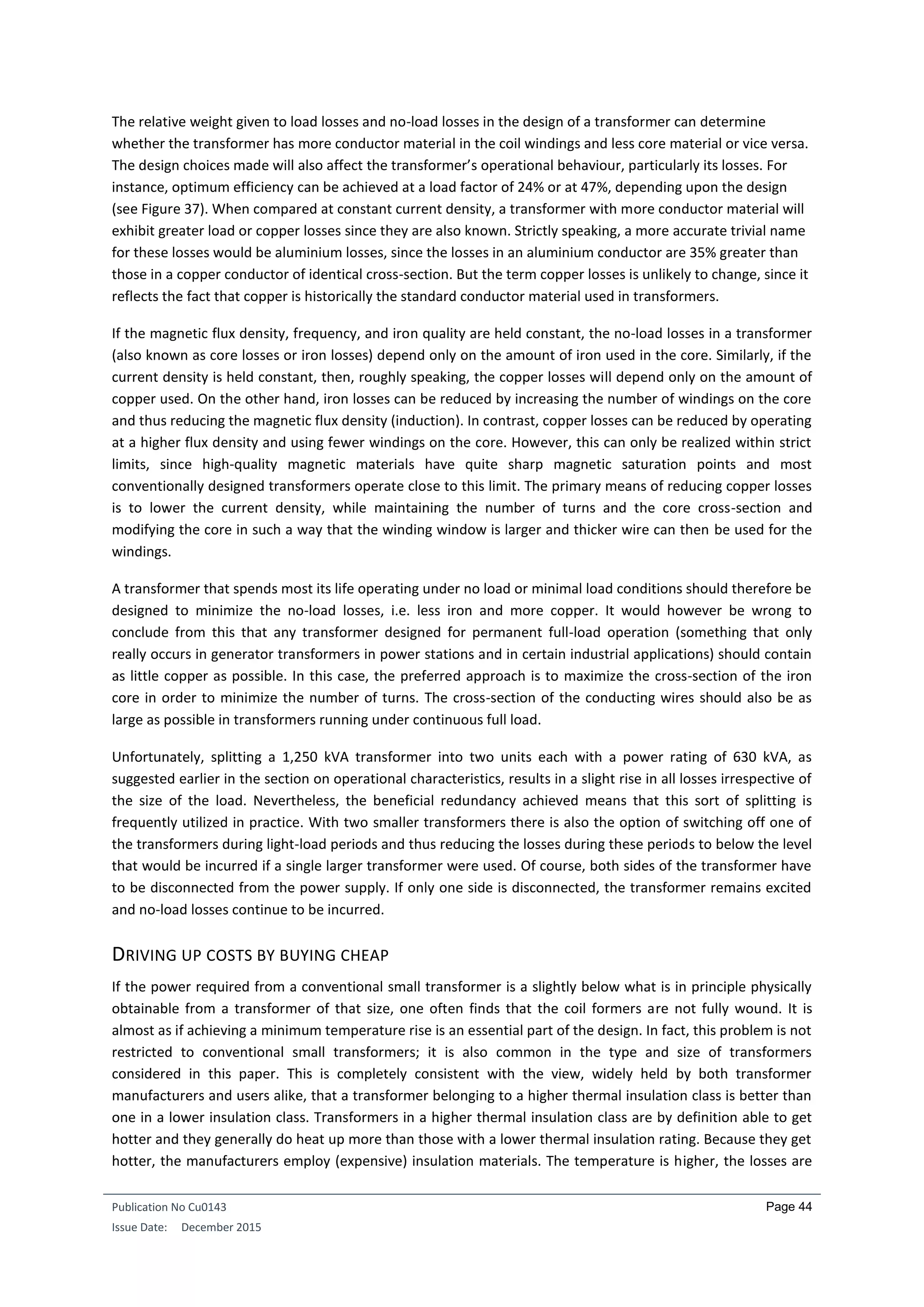
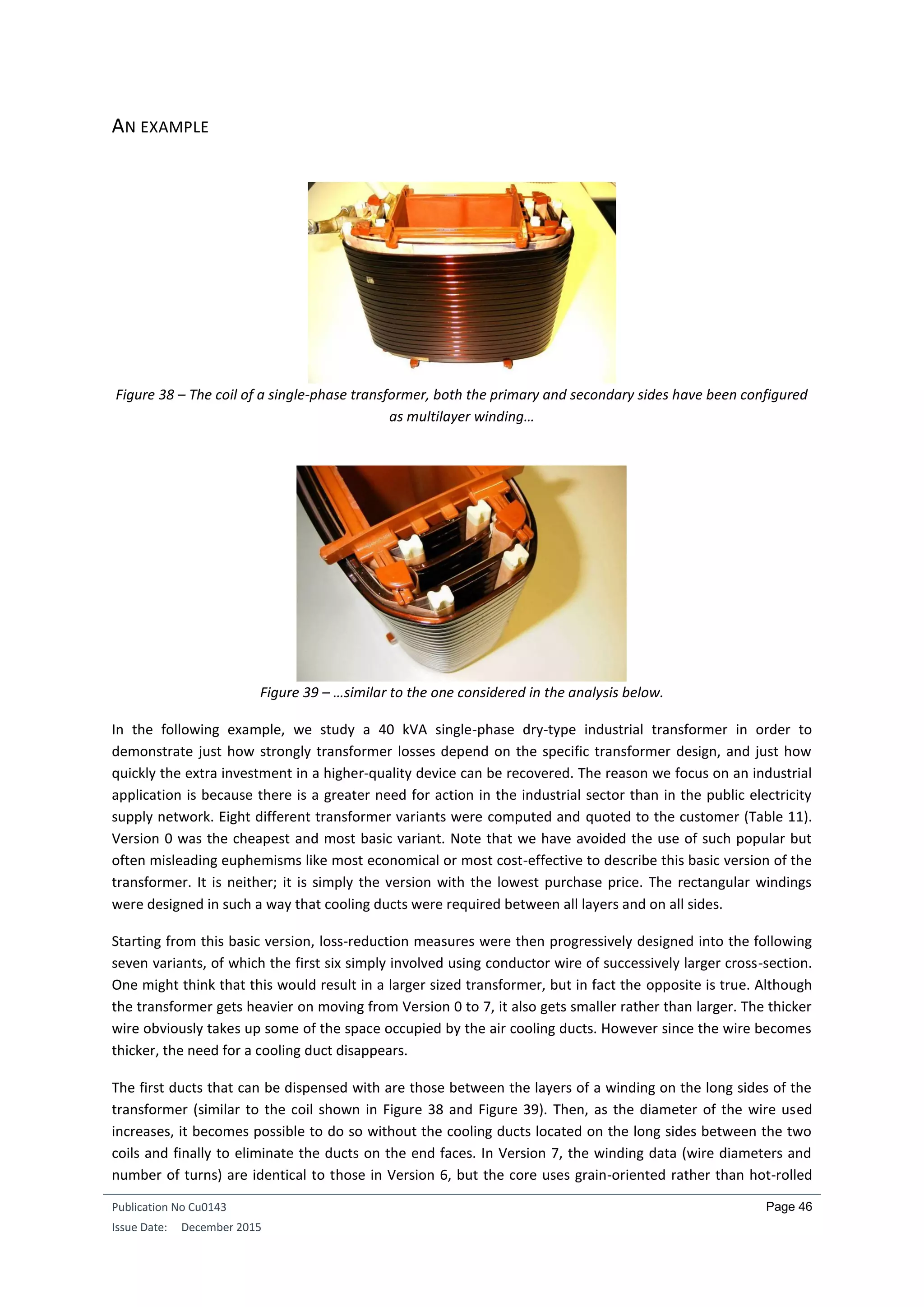
Page 47
sheet steel. Although moving from Version 6 to 7 involves only a change in the core material, the copper losses
also decrease due to the higher magnetizability of the grain oriented steel. The stack height of the core in
Version 7 is lower and the average length of a turn is therefore shorter.
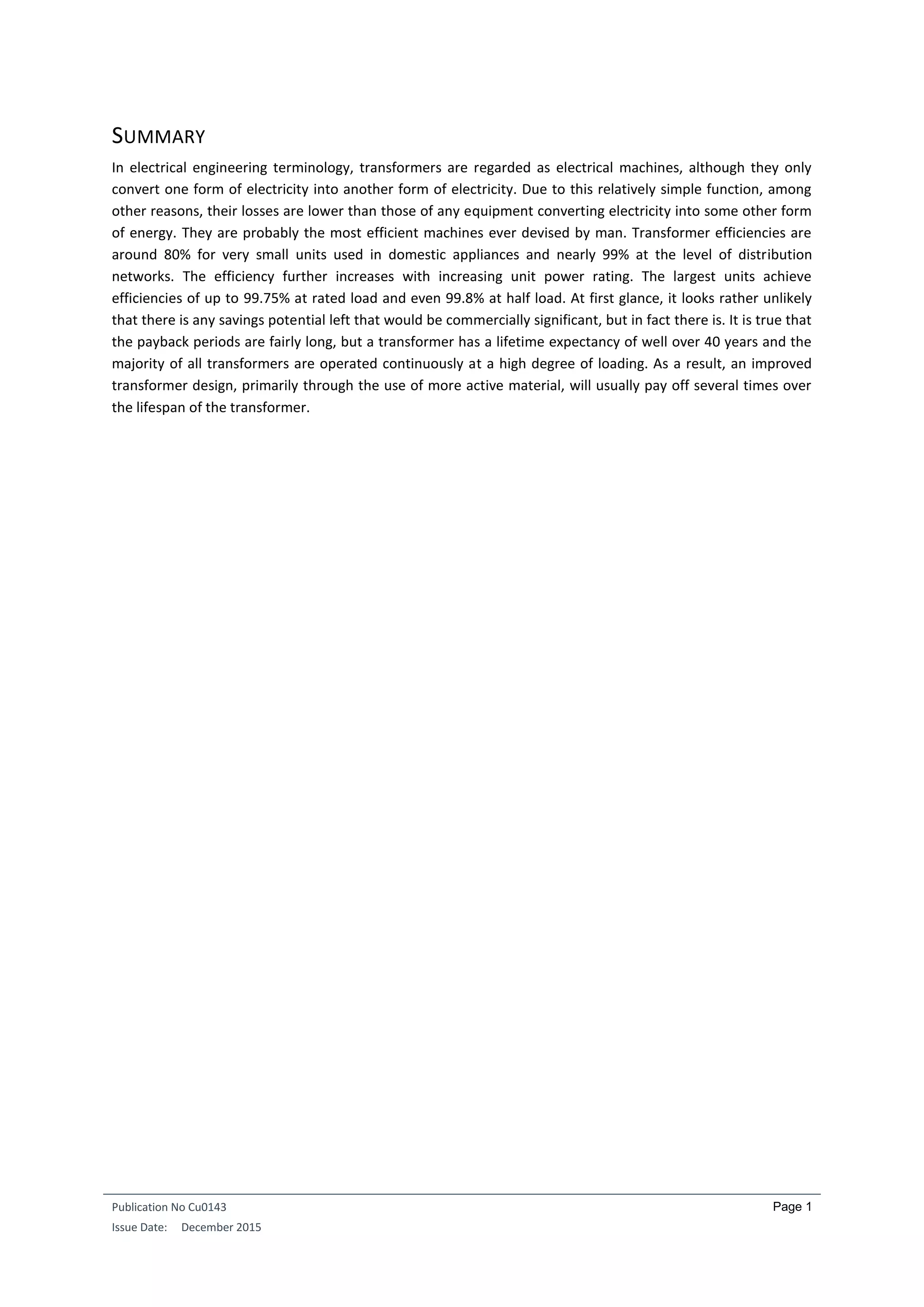
Table 11 – Improving a cheap transformer (Version 0) in seven steps.
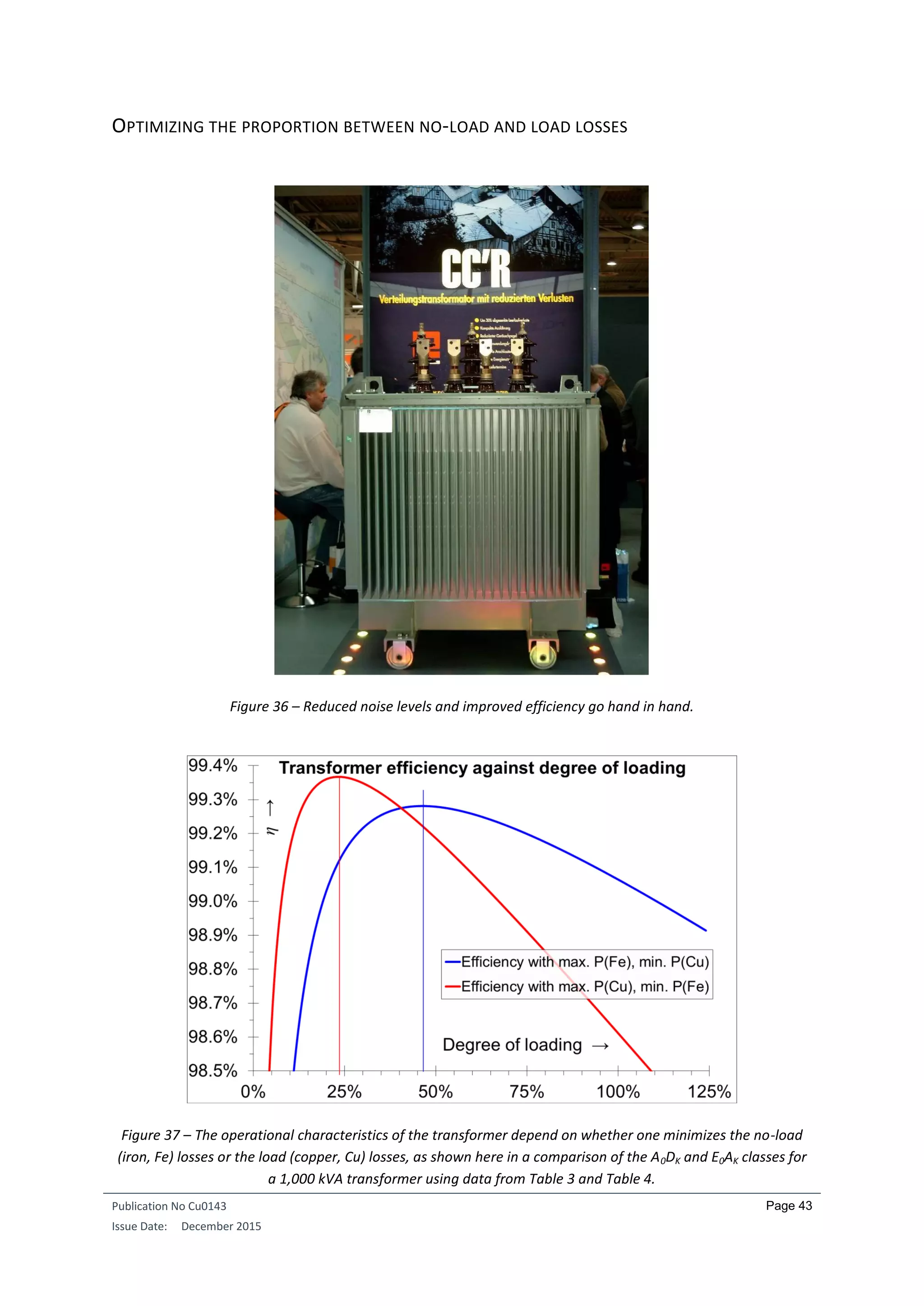
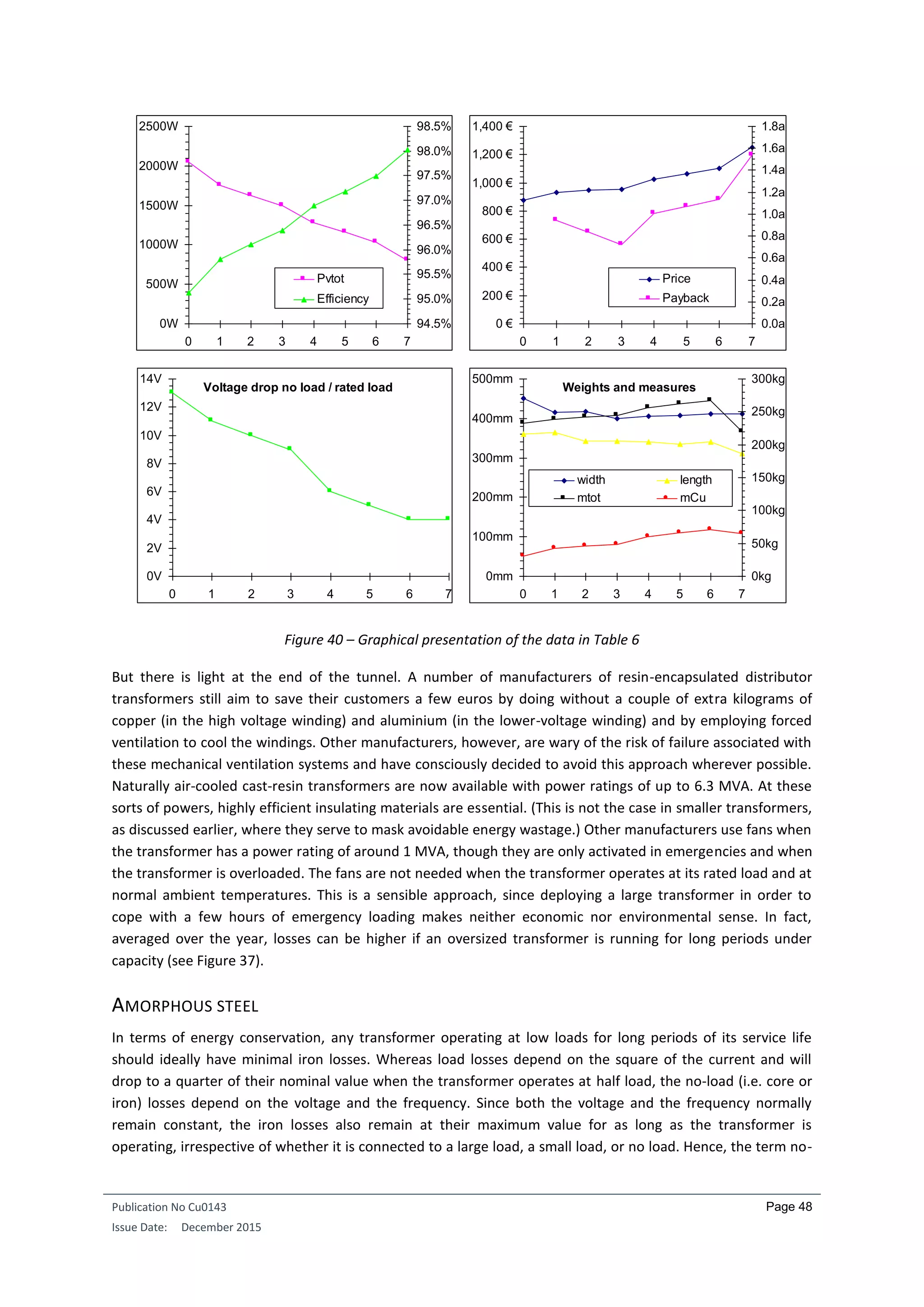
The effects of the stepwise introduction of loss-reducing measures are not immediately apparent in the data in
Table 11 and for this reason have been presented graphically in Figure 40. Two results stand out straight away:
Viewed across the series of improvements, the losses decrease significantly faster than the price rises.
The payback period is nearly always under 1.5 years, only the version with the higher quality sheet
steel core requires longer. The calculations assumed an electricity price of 10 cents per kWh, 242
working days per year, and a single eight-hour shift per day. If there are two shifts a day, the payback
periods are halved.
There is one other beneficial technical side effect from the loss reduction measures: The voltage drop in the
transformer decreases as one moves from Version 0 to 7. This is not always advantageous, especially in
transformers larger than the one considered here where a defined voltage drop is highly desirable. In large
transformers, cooling and electrical insulation requirements mean that it is not possible to eliminate the
cooling ducts. But the example transformer is relatively small, and both the input and output sides are in the
low-voltage range. Furthermore, a small voltage drop (both ohmic and inductive) was advantageous given the
particular industrial process under consideration.
When asked one year later about which of the eight variants the customer finally chose, the manufacturer
became a little embarrassed: ‘I really ought not to say. The customer went for the cheapest product. But not
only that, he also got the loads wrong. So one by one, the transformers are now burning out.’ Any one of the
improved transformer variants 5, 6, or 7 would have had sufficient reserve capacity to cope with the erroneous
load specifications and to prevent transformer failure.
Channels / Design Measures & Weights Calculated Electrical Values Pay-
Ver-
sion
betw. core &
LV winding
in LV winding
betw. LV &
HV winding
in HV winding
stack
height
width length mFe mCu mtot Pv Fe Pv Cu Pvtot U
Price back
time
front
[mm]
long
[mm]
front
[mm]
long
[mm]
front
[mm]
long
[mm]
front
[mm]
long
[mm]
[mm] [mm] [mm] [kg] [kg] [kg] [W] [W] [W] [V] [%] [€] [a]
0 10 10 10 10 10 10 10 10 100 450 360 202 30.7 232.7 417 1634 2051 13 95.1% 877 ---
1 10 10 10 0 10 10 10 0 100 415 365 196 42.4 238.4 406 1343 1749 11 95.8% 932 0.944
2 10 10 0 0 10 10 10 0 100 417 342 196 46.6 242.6 406 1217 1623 10 96.1% 946 0.839
3 10 10 0 0 10 0 10 0 100 400 342 196 48.2 244.2 406 1090 1496 9 96.4% 955 0.723
4 10 10 0 0 10 10 0 0 100 406 340 196 59.9 255.9 406 874 1280 6 96.9% 1027 1.004
5 10 10 0 0 0 0 0 0 100 408 335 196 65.9 261.9 406 753 1159 5 97.2% 1062 1.072
6 As in 5, but with even thicker wire 100 412 341 196 71.3 267.3 406 626 1032 4 97.5% 1100 1.133
7 As in 5, but with grain-oriented steel, lower stack height 80 412 311 155 64.7 219.7 223 580 803 4 98.0% 1249 1.541](https://image.slidesharecdn.com/cu0143-an-distributiontransformersv3-190429221715/75/Transformers-in-Power-Distribution-Networks-50-2048.jpg)
![Publication No Cu0143
Issue Date: December 2015
Page 52
In Europe, some believe that the introduction of higher voltage levels would also help to reduce the amount of
electrical energy consumed illegally—referred to euphemistically as non-technical losses’. Transformers as
anti-theft devices? It has even been suggested that the introduction of the lower frequency of 16.7 Hz for the
railway traction power grids used in Germany, Switzerland, Austria, and a number of Scandinavian countries
also served the same purpose. The truth, however, is that the lower frequency helps to reduce commutation
problems affecting the ac commutating series motors (universal motors) that power the traction units.
OUTLOOK
While switched-mode power supplies have replaced small transformers in numerous applications, there is
presently no sign that conventional grid transformers will be replaced by any other technology in the near
future. There are suggestions that the extra high voltage level 220 kV will disappear over the long term and
that at some even later date the 380 kV level will be replaced by a DC network
17
. Such developments would
dispense with the need for at least some of the transformers presently required. Regarding energy loss
however, these changes would be essentially neutral, since the inverters and the requisite interference
suppression filters would also generate losses of a similar magnitude.
Attempts have also been made to develop low-loss transformers with superconducting coils
18
. Unfortunately,
these conductors are only really loss-free when conducting direct current. The iron losses can even rise if the
core is also cooled. A further problem is that cooling power has to be supplied continuously at its maximum
required level, thus increasing the no-load losses, despite the fact that in practice, the transformer hardly ever
runs at full load, or if it does, then only for a short time. When all these factors are taken into account, overall
loss reductions turn out to be minimal. The one place where superconducting transformers can be used
effectively is in railway vehicles. Once these transformers go into industrial production they will save not only
weight (and therefore extra energy), but also space. Weight and space limitations in railway vehicles also mean
that the transformers currently in use in railway vehicles are working at their design limits and are thus
significantly less efficient than comparable grid transformers.
17
Fassbinder, Stefan: ‘Hochspannungs-Gleichstrom-Übertragung (HGÜ)’ [‘High-voltage DC power
transmission’], in de, vol. 11/2001, p. gig9, appears in DKI reprint s180 ‘Drehstrom, Gleichstrom, Supraleitung –
Energie-Übertragung heute und morgen’ [‘Three-phase AC, DC and superconducting systems – Power
transmission now and in the future’] from the German Copper Institute (DKI), Düsseldorf.
18
Fassbinder, Stefan: ‘Supraleitung – ein Teil zukünftiger Energieversorgung?’ [‘Superconductivity – What part
will it play in energy supplies of the future?], in de, vol. 9/2001, p. 38, appears in DKI reprint s180 ‘Drehstrom,
Gleichstrom, Supraleitung – Energie-Übertragung heute und morgen’ [‘Three-phase AC, DC and
superconducting systems – Power transmission now and in the future’] from the German Copper Institute
(DKI), Düsseldorf.](https://image.slidesharecdn.com/cu0143-an-distributiontransformersv3-190429221715/75/Transformers-in-Power-Distribution-Networks-55-2048.jpg)
![Publication No Cu0143
Issue Date: December 2015
Page 55
where n is the harmonic order and In is the associated current expressed as a fraction of the rated current, as
in the numerical example discussed above. But this number is only of use if the terms of reference are known,
i.e. if we know what fraction of the transformer’s losses are made up by the eddy-current losses PSupp.
Normally, though, the only losses (if any) stated on the rating plate are the iron losses P0 and the copper losses
PCu.
In Europe, it is not the K factor, but factor K that is computed, in accordance with harmonization document HD
538.3.S1:
𝐾 = [1 +
𝑒
1 + 𝑒
(
𝐼ℎ
𝐼
)
2
∑ (𝑛 𝑞
(
𝐼 𝑛
𝐼1
)
2
)
𝑛=𝑁
𝑛+2
]
0.5
Where
𝐼 = (∑(𝐼 𝑛)2
𝑛=𝑁
𝑛=1
)
0.5
= 𝐼1 [∑ (
𝐼 𝑛
𝐼1
)
2𝑛=𝑁
𝑛=1
]
0.5
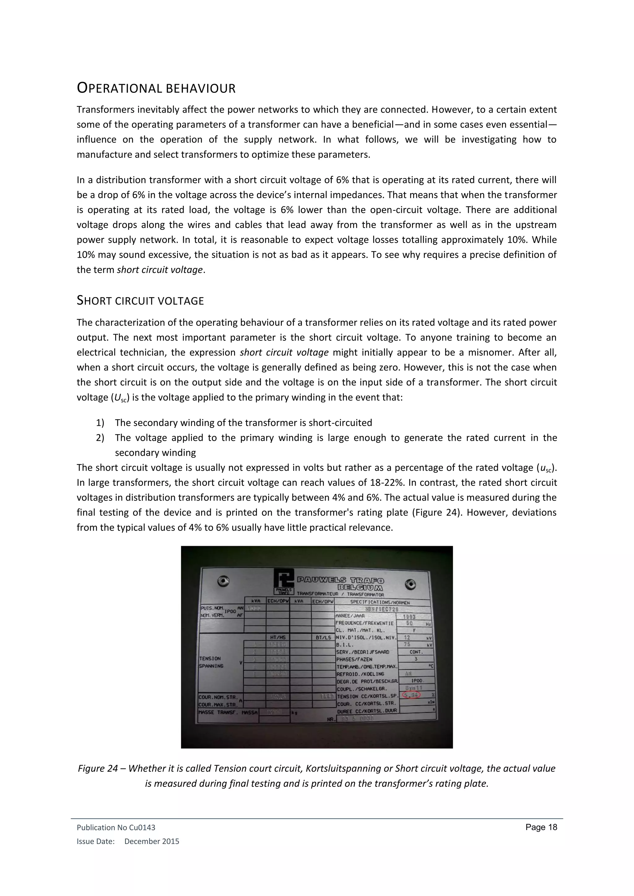
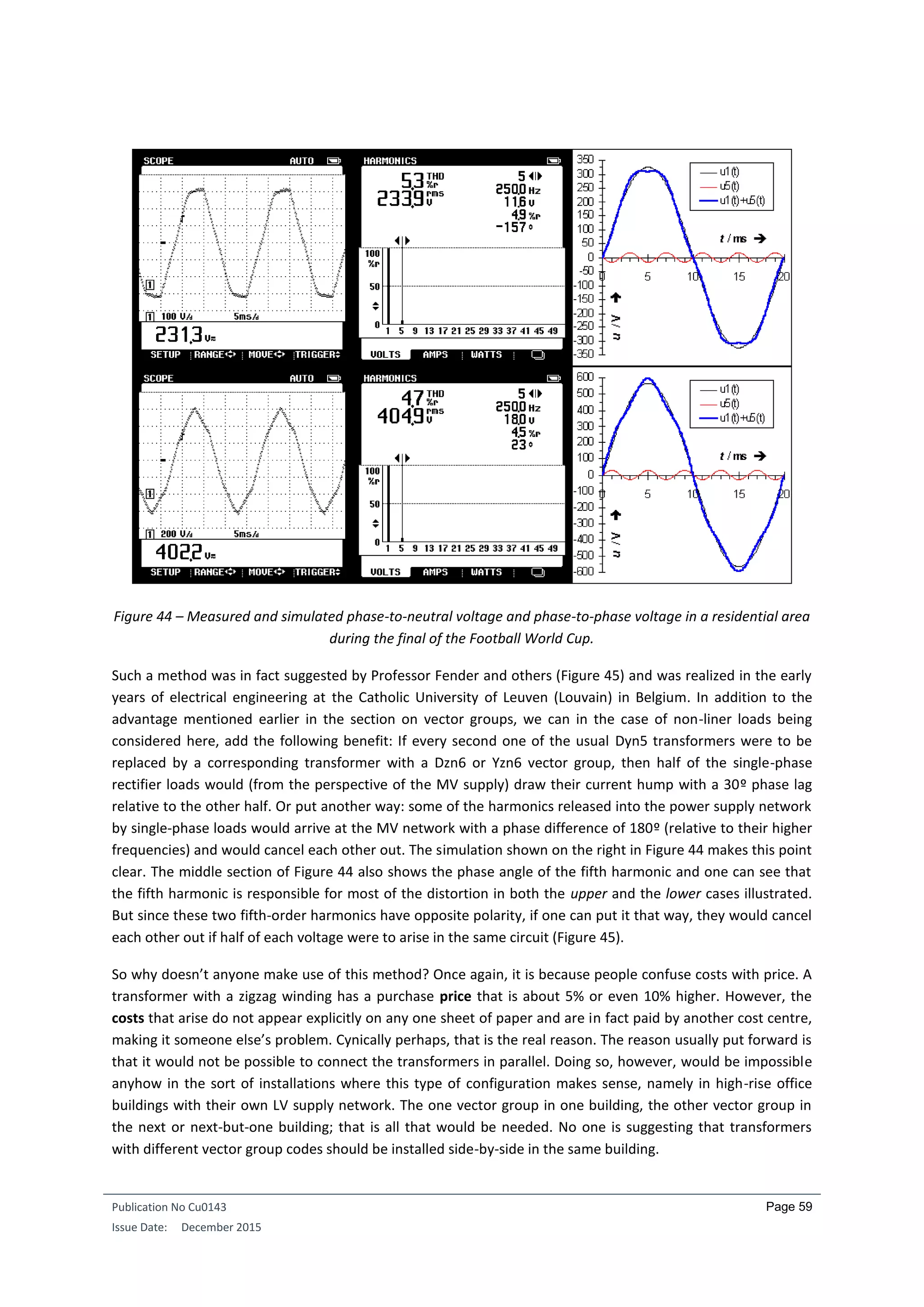
Figure 43 – Current and harmonic spectrum of an 11 watt compact fluorescent lamp (CFL). Top: CFL connected
to a transformer driving an average load in a residential area. Bottom: Simulation of a transformer operating
at its rated current and driving only CFLs.
That is probably enough to frighten most people off. If an electrical engineer or technician working on real
practical problems puts in the hard work and succeeds in correctly applying these exact formulae, he or she is
still left with the question of just what these results are actually saying and how exact they really are. Since the
transformer system being planned does not actually exist, the output values fed into the equations above can
only be based on assumptions, guesswork, or experience. Clearly neither prior measurement on the system
nor prior questioning of the subsequent user is possible. Many buildings today are planned and built and only
then does the owner seek tenants or buyers. Consequently, the harmonic profile of the power supply system is
unknown at the time of planning. We should no doubt adopt a more practical approach to this problem.](https://image.slidesharecdn.com/cu0143-an-distributiontransformersv3-190429221715/75/Transformers-in-Power-Distribution-Networks-58-2048.jpg)

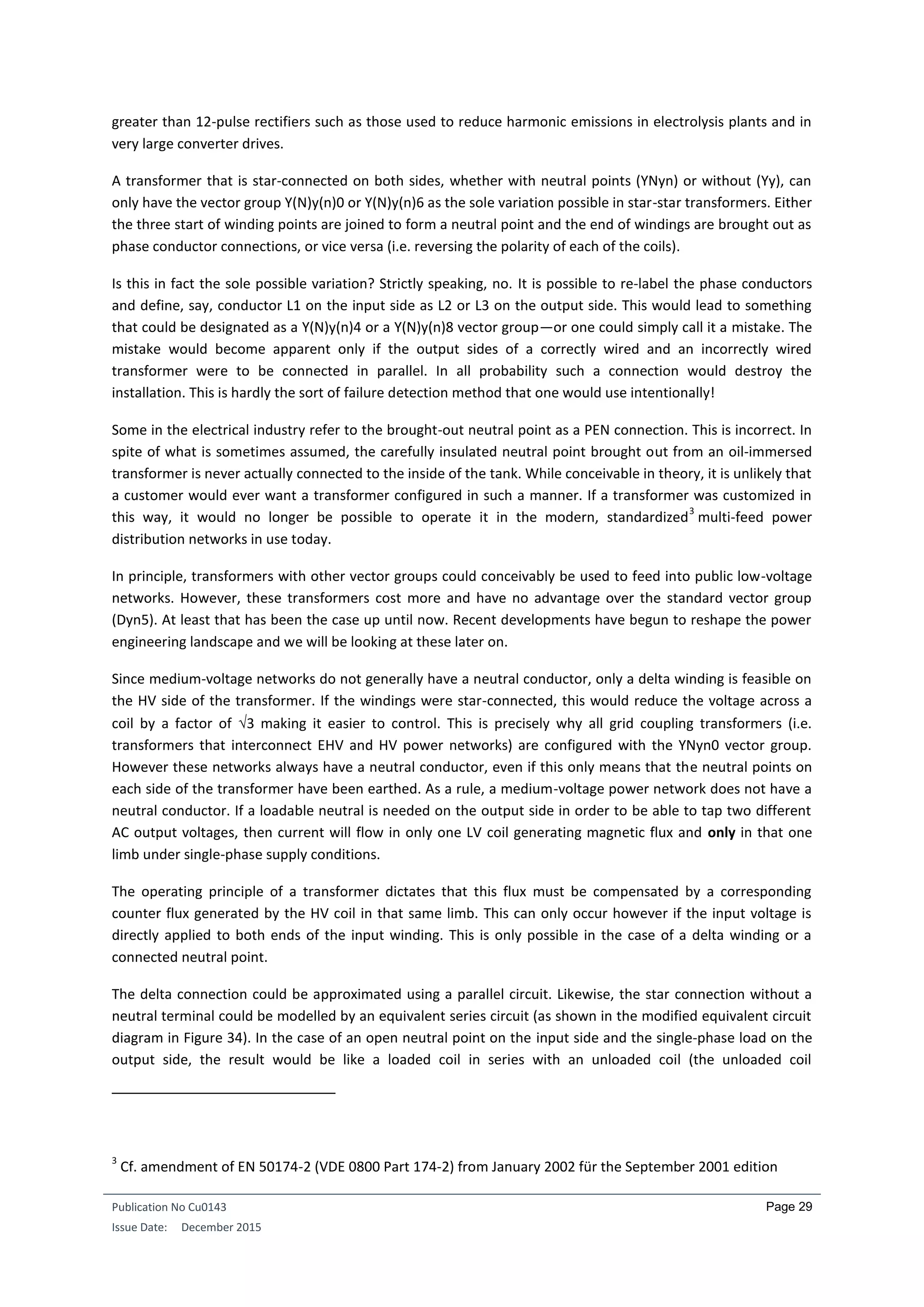
This document discusses the applications and efficiencies of transformers in power distribution networks, highlighting their role in electricity transmission at high voltages to reduce power loss. Transformers are noted for their high efficiency, with larger units achieving efficiencies of up to 99.8%, and the potential for cost savings through improved designs over their long lifespans. The document also emphasizes the importance of transformer design, manufacturing, and cooling methods to enhance performance and efficiency across different applications.


