Downloaded 16 times


![By Mohammed AboAjmaa SDU
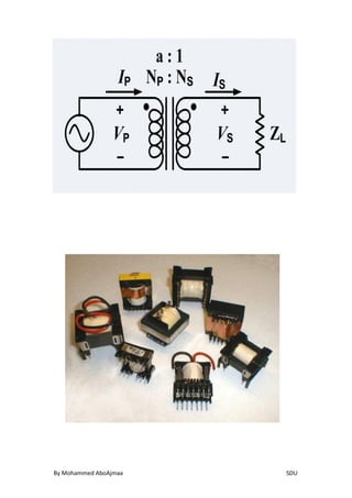
PRINCIPLES For Transformer:
It is very common, for simplification or approximation purposes, to
analyze the transformer as an ideal transformer model as
represented in the two images. An ideal transformer is a
theoretical, linear transformer that is lossless and
perfectly coupled; that is, there are no energy losses and flux is
completely confined within the magnetic core. Perfect coupling
implies infinitely high core magnetic permeability and winding
inductances and zero net magneto motive force. varying current in
the transformer's primary winding creates a varying magnetic flux
in the core and a varying magnetic field impinging on the
secondary winding. This varying magnetic field at the secondary
induces a varying electromotive force(EMF) or voltage in the
secondary winding. The primary and secondary windings are
wrapped around a core of infinitely high magnetic permeability[d]
so that all of the magnetic flux passes through both the primary
and secondary windings with a voltage connected to theprimary
winding and load impedance connected to the secondary winding
the transformer currents flow in the indicated directions. (See also
Polarity.)
According to Faraday's law of induction, since the same magnetic
flux passes through both the primary and secondary windings in an
ideal transformer, a voltage is induced in each winding]
, according
to eq. (1)](https://image.slidesharecdn.com/transformer-150521135010-lva1-app6892/85/Transformer-Electromagnetic-WavesTheory-7-320.jpg)


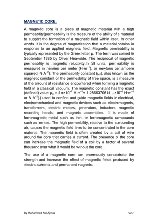


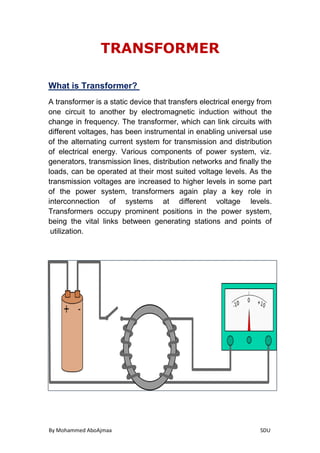
This document provides information about transformers and their components. It discusses how transformers work using electromagnetic induction to transfer energy between circuits without a direct electrical connection. The key components of a transformer are described, including the magnetic core made of silicon steel, the windings, insulation and cooling using mineral oil. Ideal transformer theory is also covered, explaining voltage and current ratios based on winding turns.


![Chapter_3-Transformers[1]-1.pdf](https://cdn.slidesharecdn.com/ss_thumbnails/chapter3-transformers1-1-230622173423-be6efc48-thumbnail.jpg?width=640&height=640&fit=bounds)


