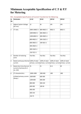
Minimum Acceptable Specification of C.T & P.T
for Metering
Min. Acceptable Specification of Current Transformer for Metering:
Sr.
No
Particulars 11 kV 33 kV 132 kV 220 kV
1 Highest System Voltage
(kV rms)
12 36 145 245
2 CT ratio. 2000-1000/1-1 800-400/1-1 400/1-1 800/1-1
1600-800/1-1 600-300/1-1
1200-600/1-1 400-200/1-1
800-400/1-1 300-150/1-1
600-300/1-1 100-50/1-1
400-200/1-1
300-150/1-1
150-75/1-1
3 Number of metering
cores
Two Nos Two Nos Two Nos Two Nos
4 Rated continuous thermal
current.
120% of rated
primary current
120% of rated
primary current
120% of rated
primary current
120% of rated
primary current
5 Rated short time thermal
current of primary for 1
sec. (kA)
25 25 31.5 40
6 CT characteristics :
a) Rated primary current
(Amps.)
2000-1000 800-400 400 800
1600-800 600-300
1200-600 400-200
800-400 300-150
600-300 100-50
400-200
300-150
150-75
(b) Rated Secondary
current (Amps.)
1 1 1 1
(c) Class of accuracy. 0.2 0.2 0.2 0.2
(d) Max. instrument
security factor
5 5 5 5
(e) Rated burden (VA). 30 30 30 40
7 IS to which CT conforms.
8 IS to which insulating oil
conforms.
Min. Acceptable Specification of Voltage Transformer for Metering:
Sr.
No
Particulars 245 kV CVTs 145 kV
CVTs
1 Highest SystemVoltage (kV) 245 kV 145 kV
2 Rated Capacitance (pF) 4400 pf with tolerance + 10%
and – 5%
3 For low voltage terminal over
entire carrier frequency
range.
(a) Stray capacitance Shall not exceed 200 pf
(b) Stray conductance Shall not exceed 20 us
4 (a) High
frequency capacitance
for entirecarrier frequency
range
within 80% to 150% of rated
capacitance
(b) Equivalent series
resistance over the entire
frequency range.
less than 40 Ohms
5 No. of secondary windings for
potential device.
Two Two
6 Transformation ratio:
(i) Winding –I 20 kV- /3/110 -/3V
(ii) Winding –II 20 kV- /3/110 -/3V
7 Rated secondary burden
(i)Winding –I (VA) 50 VA 50 VA
(ii) Winding –II (VA) 50 VA 50 VA
8 Accuracy Class :
(i)Winding –I (VA) 0.2 for metering
(ii) Winding –II (VA) 0.2 for metering
9 Voltage factor for winding –
IVoltage factor for winding –
II
1.2 Cont. & 1.5 for 30 secs.1.2
Cont. & 1.5 for 30 secs.
10 IS to which CVTs conform. IS 3156 with latest amendment
11 IS to which Insulating Oil
conform.
IS 335 with latest amendment
Minimum Acceptable Specification of Single Phase PT for Metering:
Sr.NoParticulars 33 kV 11 kV
1 Highest System Voltage (kV rms) 36 12
2 Transformation ratio. 33kV/
V3/ 110/
V3
11 kV/110 V
3 Number of windings. Two Two
4 Rated output/ burden (VA) per winding
/phase.
50 50
5 Accuracy class. (At 10 to 100% of VA
burden)
0.2 0.2
6 Rated voltage factor and duration. 1.2 Continuous & 1.5 for 30
secs.
7 IS to which PT conforms. 3156 with latest
amendment

Ct & pt specification

  • 1.
    Minimum Acceptable Specificationof C.T & P.T for Metering Min. Acceptable Specification of Current Transformer for Metering: Sr. No Particulars 11 kV 33 kV 132 kV 220 kV 1 Highest System Voltage (kV rms) 12 36 145 245 2 CT ratio. 2000-1000/1-1 800-400/1-1 400/1-1 800/1-1 1600-800/1-1 600-300/1-1 1200-600/1-1 400-200/1-1 800-400/1-1 300-150/1-1 600-300/1-1 100-50/1-1 400-200/1-1 300-150/1-1 150-75/1-1 3 Number of metering cores Two Nos Two Nos Two Nos Two Nos 4 Rated continuous thermal current. 120% of rated primary current 120% of rated primary current 120% of rated primary current 120% of rated primary current 5 Rated short time thermal current of primary for 1 sec. (kA) 25 25 31.5 40 6 CT characteristics : a) Rated primary current (Amps.) 2000-1000 800-400 400 800 1600-800 600-300 1200-600 400-200 800-400 300-150 600-300 100-50 400-200 300-150 150-75
  • 2.
    (b) Rated Secondary current(Amps.) 1 1 1 1 (c) Class of accuracy. 0.2 0.2 0.2 0.2 (d) Max. instrument security factor 5 5 5 5 (e) Rated burden (VA). 30 30 30 40 7 IS to which CT conforms. 8 IS to which insulating oil conforms. Min. Acceptable Specification of Voltage Transformer for Metering: Sr. No Particulars 245 kV CVTs 145 kV CVTs 1 Highest SystemVoltage (kV) 245 kV 145 kV 2 Rated Capacitance (pF) 4400 pf with tolerance + 10% and – 5% 3 For low voltage terminal over entire carrier frequency range. (a) Stray capacitance Shall not exceed 200 pf (b) Stray conductance Shall not exceed 20 us 4 (a) High frequency capacitance for entirecarrier frequency range within 80% to 150% of rated capacitance (b) Equivalent series resistance over the entire frequency range. less than 40 Ohms 5 No. of secondary windings for potential device. Two Two 6 Transformation ratio: (i) Winding –I 20 kV- /3/110 -/3V (ii) Winding –II 20 kV- /3/110 -/3V 7 Rated secondary burden (i)Winding –I (VA) 50 VA 50 VA
  • 3.
    (ii) Winding –II(VA) 50 VA 50 VA 8 Accuracy Class : (i)Winding –I (VA) 0.2 for metering (ii) Winding –II (VA) 0.2 for metering 9 Voltage factor for winding – IVoltage factor for winding – II 1.2 Cont. & 1.5 for 30 secs.1.2 Cont. & 1.5 for 30 secs. 10 IS to which CVTs conform. IS 3156 with latest amendment 11 IS to which Insulating Oil conform. IS 335 with latest amendment Minimum Acceptable Specification of Single Phase PT for Metering: Sr.NoParticulars 33 kV 11 kV 1 Highest System Voltage (kV rms) 36 12 2 Transformation ratio. 33kV/ V3/ 110/ V3 11 kV/110 V 3 Number of windings. Two Two 4 Rated output/ burden (VA) per winding /phase. 50 50 5 Accuracy class. (At 10 to 100% of VA burden) 0.2 0.2 6 Rated voltage factor and duration. 1.2 Continuous & 1.5 for 30 secs. 7 IS to which PT conforms. 3156 with latest amendment