Downloaded 158 times
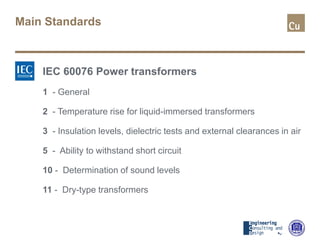
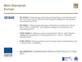
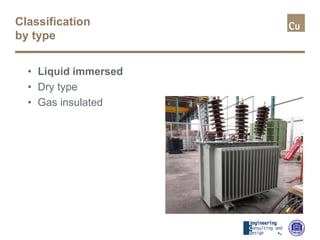
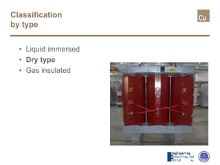
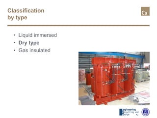
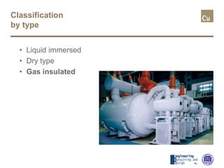
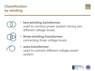
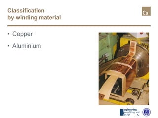
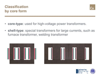
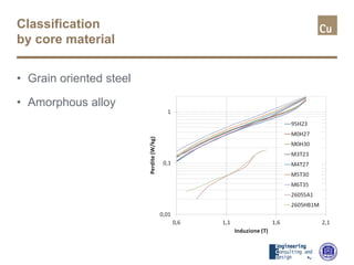
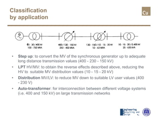
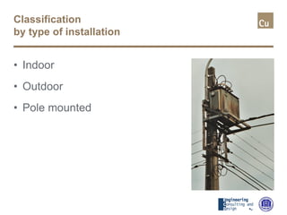
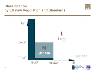
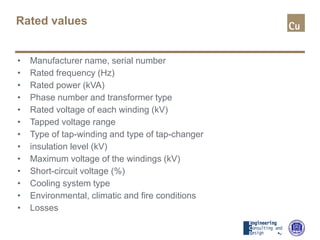
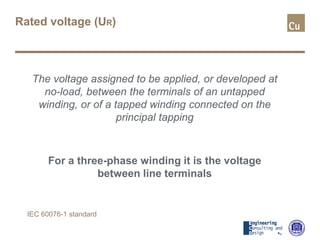
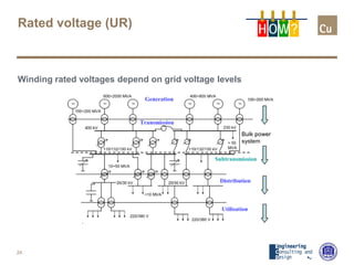
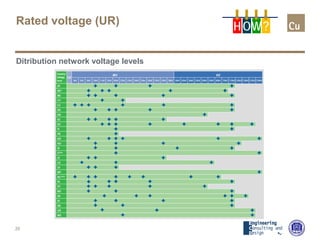


The document is an introduction to power transformers, outlining key standards, classifications, rated values, and tolerances as per various IEC and EU regulations. It details classification by type, winding, application, and installation, along with specific rated values such as power, voltage, and frequency. Additionally, it discusses environmental conditions, cooling types, and relevant regulations pertaining to transformer design and performance.


![1502957304lectrure_1 [Autosaved].pptx](https://cdn.slidesharecdn.com/ss_thumbnails/1502957304lectrure1autosaved-230615110736-8bee5be3-thumbnail.jpg?width=640&height=640&fit=bounds)


