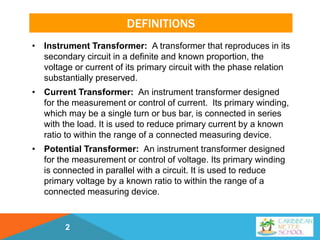
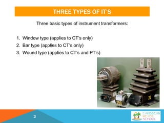
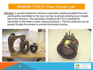
J A N U A R Y 2 9 , 2 0 1 9
A T L A N T A , G A
CARIBBEAN METER SCHOOL
Introduction to CTs and
PTs
Art Lowery, Georgia Power
DEFINITIONS
• Instrument Transformer: A transformer that reproduces in its
secondary circuit in a definite and known proportion, the
voltage or current of its primary circuit with the phase relation
substantially preserved.
• Current Transformer: An instrument transformer designed
for the measurement or control of current. Its primary winding,
which may be a single turn or bus bar, is connected in series
with the load. It is used to reduce primary current by a known
ratio to within the range of a connected measuring device.
• Potential Transformer: An instrument transformer designed
for the measurement or control of voltage. Its primary winding
is connected in parallel with a circuit. It is used to reduce
primary voltage by a known ratio to within the range of a
connected measuring device.
2
THREE TYPES OF IT’S
Three basic types of instrument transformers:
1. Window type (applies to CT’s only)
2. Bar type (applies to CT’s only)
3. Wound type (applies to CT’s and PT’s)
3
WINDOW TYPE CT “Pass through type”
Definition: A current transformer that has a secondary winding insulated from and
permanently assembled on the core, but has no primary winding as an integral
part of the structure. (The secondary winding of all CT’s is intended for
connection to the meter or other measuring device.) The line conductor can be
passed through the window to provide the primary winding.
4
BAR TYPE CT
Definition: A current transformer that has a fixed, insulated straight
conductor in the form of a bar, rod, or tube that is a single primary
turn passing through the magnetic circuit and that is assembled to the
secondary core and winding.
5
WOUND TYPE CT
Definition: A current transformer that has a primary winding consisting of
one or more turns mechanically encircling the core.The primary and
secondary windings are insulated from each other and from the core
and are assembled as an integral structure.
6
WOUND TYPE PT
All potential transformers are of the wound-type. The definition of a
wound-type potential transformer would essentially be the same as a
wound-type current transformer, having both the primary and secondary
windings encircling the core and insulated from each other.
7
HIGH VOLTAGE INSTRUMENT TRANSFORMERS
Transmission Voltages
46 to 500 kV
8
25KV TO 500KV OIL-FILLED INSTRUMENT
TRANSFORMERS
9
MEDIUM VOLTAGE INSTRUMENT
TRANSFORMERS
Distribution Voltages
4 to 25 kV
10
LOW VOLTAGE INSTRUMENT TRANSFORMERS
Secondary Voltages
600 Volts or Less
11
CURRENT TRANSFORMER RATIO
• A current transformer’s ratio is always
expressed with a secondary rating of 5
amps.
• The current transformer illustrated
here would have a ratio of 1200 to 5.
• 1200 amps flowing through its primary
winding (line wire) would cause 5
amps to flow to the meter
12
CURRENT TRANSFORMER TURNS RATIO
• A current transformer will
have few primary turns
and many secondary
turns.
• The window-type CT to
the right will have one
primary turn (the
customer’s line wire) and
120 secondary turns.
• The turns ration is 120:1
13
CURRENT TRANSFORMER TURNS RATIO
• The wound-type current
transformer to the right has
two primary turns.
• The conductor making up the
primary winding consists of
multiple layers of thin copper
strapping approximately four
inches wide.
• The secondary winding
consists of many turns of
small copper wire.
14
POTENTIAL TRANSFORMER RATIO
• Potential transformers are always designed
to step the primary voltage down to 120 volts,
or 115 volts in the case of high voltage
transformers.
• Potential transformers will have a
designated primary voltage rating.
• The PT illustrated at the right is designed to
step 7200 volts down to 120 volts. Its ratio is
60 to 1.
• Potential transformers are designed for
specific line voltages. A PT with a ratio of 2:1 is
only designed to step 240 volts down to 120
volts. It should never, for example, be used to
step 480 volts down to 240 volts. Voltages
higher than rated may cause saturation of the
core, resulting in large errors and excessive
heating.
15
POTENTIAL TRANSFORMER RATIO
Due to mislabeling of a substation transformer 14,400 volts was applied to these
60:1 potential transformers.
16
POTENTIAL TRANSFORMER RATIO
Miscommunications resulted in this cluster with 20:1 PTs being installed on the
high side of a 12470/7200V transformer bank.
17
POTENTIAL TRANSFORMER RATIO
4160 Volts was applied to this 20:1 PT.
18
POTENTIAL TRANSFORMER RATIO
480 Volts was applied to
this 2:1 PT.
19
POTENTIAL TRANSFORMER OVER VOLTAGE
IEEE Standard C57.13-2008
The IEEE Standard defines five distinct groups of voltage transformers
and provides ratings for each group. All must be capable of
operating accurately at 110% above rating voltage continuously
provided the secondary burden in VA at this voltage rating does not
exceed the thermal rating.
GPC typically uses “Group 1” Voltage Transformers:
• Primary voltage may be connected line-to-line or line-to-ground.
• Capable of operations at 125% of rated voltage on an emergency
basis. (eight hours)
• Operation in emergency range will reduce life expectancy.
20
POTENTIAL TRANSFORMER TURNS RATIO
• The primary winding
of a potential
transformer will
consist of many turns
of small wire.
• The secondary
winding will be fewer
turns of larger wire.
21
BURDEN
• Burden is the term used to refer to the load on the secondary circuit
of instrument transformers.
• An instrument transformer’s “rated burden” is the load which may be
imposed on the transformer secondary circuit by associated meter
coils, leads and other connected devices without causing an error
greater than the stated accuracy classification.
• Current transformer rated burdens are normally expressed in ohms
impedance such as B-0.1, B-0.2, B-0.5 or B-1.8.
• Potential transformer rated burdens are normally expressed in volt-
amperes at a designated power factor. This VA rating is typically
represented by the letters W, X, M, Y, Z, or ZZ. For example, the
letter “Y” designates a burden of 75 VA @ .85 power factor.
22
ANSI STANDARD BURDENS FOR
VOLTAGE TRANSFORMERS
23
ACCURACY OF INSTRUMENT
• Two sources of error determine the accuracy of instrument transformers:
(1) Ratio error
(2) Phase angle error
• The “accuracy classification” of instrument transformers includes a correlation
between ratio correction factor and phase angle so as to show the overall
effect on meter registration.
• The ratio correction factor (RCF) is the ratio of the true ratio to the
marked ratio.
• The phase angle of an instrument transformer is the phase displacement,
in minutes, between the primary and secondary values.
• The transformer correction factor (TCF) is the correction for overall error
due to both ratio error and phase angle.
• ANSIhas established accuracy classes for both current and potential
transformers.Typical classifications are 0.3% error for metering, and 0.6%
to 1.2% error for indicating instruments. (ANSI C57.13)
24
ACCURACY IS BURDEN DEPENDENT
• An accuracy classification for an instrument transformer
includes the standard burden as well as the maximum percent
error limits for ratio and phase angle error.
• The standard burdens for which a transformer’s accuracy
rating applies will be designated along with the accuracy rating.
25
CURRENT TRANSFORMER ACCURACY
The corresponding ratio correction factor and phase angle for any
point inside the 0.3 class parallelogram for 100% rated current will
always give a transformer correction factor between .997 and
1.003.
26
CURRENT TRANSFORMER ACCURACY
• In addition to burden (secondary load), a CT’s accuracy is affected by the
Metered Load (primary current).
• The limit of permissible error in a current transformer for a given accuracy
class has one value at 100% rated current and twice that amount of error at
10% rated current.
• Below 10 % rated current, error may be as much as 5 – 10 %.
27
CURRENT TRANSFORMER ACCURACY
Example of a CT with a rating factor of 4 and a rated burden of 1.8
28
CURRENT TRANSFORMER ACCURACY
Summary of Main Points:
• A CT’s accuracy is best between 100% rated load and it’s
maximum rated load with rating factor applied.
• Below 10% rated load, a CT’s accuracy is unknown and errors
can be significant.
• Above maximum rated load (with rating factor applied), a CT’s
core can become saturated and errors can be significant.
• A CT’s accuracy improves as secondary burden decreases.
• Errors in Current Transformer accuracy from any of the
above conditions always result in a loss for the utility.
29
SOURCES OF BURDEN ON CT’S
1. Size & Length of metering control cable.
• Resistance for # 12 copper wire is approximately .0018 Ohms per
foot.
• 50 feet of control cable = .09 Ohms burden.
2. Connections
• How many connections are in a CT’s secondary circuit?
• Quality of connections: Are they tight? Is there oxidation or
corrosion?
3. Meter
• The current coils in the meter are considered equivalent to a short
circuit and the burden imposed on the circuit is insignificant.
30
SOURCES OF BURDEN ON CT’S
• 50 feet of control cable will account for nearly all of the burden
rating of this CT.
• Any additional burden could easily exceed the accuracy rating.
31
POTENTIAL TRANSFORMER ACCURACY
The corresponding ratio correction factor and phase angle for any
point inside the 0.3 class parallelogram will always give a
transformer correction factor between .997 and 1.003.
32
POTENTIAL TRANSFORMER ACCURACY
The limit of permissible error in a potential transformer for a given
accuracy class remains constant over a range of voltage from 10%
below and 10% above rated voltage.
33
POTENTIAL TRANSFORMER ACCURACY
• The primary source of errors with potential
transformers is overloading the
transformer.
• If the load on the PT exceeds the burden
rating, metering errors can result.
• The measured voltage will be low thereby
reducing the billing to the customer.
34
CURRENT TRANSFORMER ACCURACY
An Example from the field using a Powermate 330
35
CURRENT TRANSFORMER ACCURACY
An Example from the Field using a Powermate 330
At 100% rated current,
this CT’s reference ratio
accuracy is 99.8%.
The plots in the
parallelogram show that
the burden added to the
CT’s secondary circuit had
no effect on accuracy.
36
EXTENDED RANGE MEDIUM VOLTAGE CTS
37
CURRENT TRANSFORMER RATING FACTOR
• Rating factor (RF) is a term which applies only to current transformers.
• Also known as “thermal rating factor” or “continuous thermal rating
factor.”
• It is the number by which the primary load current may be increased
over its nameplate rating without exceeding the allowable temperature
rise and accuracy requirements.
• The rating factor is temperature dependent. The ambient
temperature at which the rating factor applies will be stated.
• The standard ambient reference levels are at 30 and 55
degrees centigrade. (86 and 131 degrees Fahrenheit)
• Usually the manufacturer will only list the rating factor at 30
degrees ambient.
• It is very important that the ambient temperature be considered
when applying CT’s above the nameplate rating.
38
CURRENT TRANSFORMER RATING FACTOR
39
•If a current transformer has a rating factor of 4 at 30 degrees centigrade, it
will safely carry, on a continuous basis, 4 times the nameplate rating.
•In other words, a 200:5 CT with a RF of 4 will safely carry 800 amps at 30
degrees centigrade ambient temperature.
•We can use the formula below to determine what the CT’s rating factor
would be at 55 degrees centigrade or at any other temperature:
CURRENT TRANSFORMER RATING FACTOR
This CT pictured below will safely carry 800 amps at 30 degrees
centigrade ambient temperature.
This same CT will only
carry 590 amps at 55
degrees centigrade.
(2.95 X 200 = 590)
40
POTENTIAL TRANSFORMER THERMAL RATING
41
•Potential transformers have a thermal rating rather than a
rating factor as with a CT.
•The thermal rating designates the maximum volt-amp
burden which may be connected to its secondary without
excessive heating and possible damage to the PT.
•The thermal rating of a PT is much higher than the PT’s
accuracy burden rating, which is also expressed in volt-
amps.
“The thermal burden rating of a voltage transformer is the
volt-amperes which the voltage transformer will carry
continuously at rated voltage and frequency without
causing the specified temperature limitations to be
exceeded. “ ANSI C12.11-1978
POTENTIAL TRANSFORMER THERMAL RATING
42
BASIC IMPULSE LEVEL (BIL)
43
•The BIL rating on instrument transformers are test ratings and
never apply to actual in-service voltage.
•These test values are for factory dielectric tests that are designed
to check the insulation and workmanship of instrument
transformers.
INSULATION CLASS (IC)
44
•The insulation class indicates the level of voltage which an instrument
transformer can safely withstand between its primary and secondary
windings and between its primary or secondary winding and ground.
•Industry recommendations are that the insulation class of an instrument
transformer should be at least equal to the maximum line-to- line voltage
existing on the system at the point of connection.
•For example, any current or potential transformer used on a 14400/24940
volt wye system should be of the 25 kV insulation class. Under fault
conditions, these units could be subjected to line-to-line voltage.
• The insulation class may be designated on the name plate as:
• “IC “ (Insulation Class)
• “NSV “ (Nominal System Voltage)
• “Max. Sys. Volt.” (Maximum System Voltage)
• “Vm” (Maximum Voltage – used on Ritz name plates)
INSULATION CLASS (IC)
45
INSULATION CLASS (IC)
46
POLARITY
47
•Primary and secondary terminals of instrument transformers are said to
have the same polarity when, at a given instant, the current enters the
identified or marked primary terminal and leaves the identified or marked
secondary terminal in the same direction as though the two terminals
formed a continuous circuit.
•In the application of instrument transformers it is necessary to
understand and observe polarity markings when connecting watthour
meters to them.
•All instrument transformers, whether current or potential, will have
polarity marks associated with at least one primary terminal and one
secondary terminal.
• The polarity markings are often white dots.
•The polarity markings are sometimes a letter and number combination. H1
for the primary marking and X1 for the secondary mark.
POLARITY
48
POLARITY (CURRENT TRANSFORMERS)
49
POLARITY (POTENTIAL TRANSFORMERS)
50
SECONDARY CIRCUITS: TWO RULES TO
REMEMBER
51
THIS PT’S SECONDARY CIRCUIT WAS SHORTED
WHEN THE WRONG METER WAS INSTALLED.
52
CT SECONDARY CIRCUITS
• The current transformer has a low voltage secondary as long as the
secondary connection is a continuous connection. This continuous connection
normally exists through the metering control cable and the current coils in the
meter. The meter may be by-passed by closing the shunting device on the CT
or by opening the current switches on the test-switch block.
53
CT SECONDARY CIRCUITS
• If at any time, the secondary connection is opened and there is current
flowing in the primary, the CT becomes a step up voltage transformer and the
secondary voltage can rise to very high voltages.
• This can be understood by some basic Ohm’s Law calculations.
E = I R
With a continuous secondary connection, the resistance is very low and the voltage
remains very low. But, as the secondary circuit is opened, the resistance rises very
rapidly and the secondary voltage can quickly rise to thousands of volts. The
actual formula is:
• The high voltage that is present on the open secondary of an energized CT
poses two hazards. The first is an electrical shock hazard to personnel. The
second hazard is the breakdown of the current transformer’s insulation resulting in
damage or destruction of the transformer.
54
OSHA STANDARD 1910.269(w)(2)
55
GROUNDING IT SECONDARY CIRCUITS
• It is standard practice to ground the common or neutral
secondary wire of Potential Transformers and also the
secondary current return wire on Current Transformers.
• The Handbook for Electricity Metering states, “Grounding is a
necessary safety precaution for protection against static
voltages and insulation failure.”
• IEEE Std C57.13.3 recommends that IT secondary circuits be
grounded at only one point – preferably at the first point of
application of the circuit (switchboard, meter, etc.)
• Grounding at the IT and at the meter can cause the grounding
path to become a parallel path with the IT’s secondary circuit
– possibly resulting in the circulation of electrical noise during
normal operation or damage from high current flow during
ground-fault conditions.
56
REVIEW (NAMEPLATE INFORMATION)
57
REVIEW (NAMEPLATE INFORMATION)
58
REVIEW (NAMEPLATE INFORMATION)
59
REVIEW (NAMEPLATE INFORMATION)
60
REVIEW (NAMEPLATE INFORMATION)
61
REVIEW (NAMEPLATE INFORMATION)
62
REVIEW (NAMEPLATE INFORMATION)
63
REVIEW (NAMEPLATE INFORMATION)
64
REVIEW (NAMEPLATE INFORMATION)
65
REVIEW (NAMEPLATE INFORMATION)
66
INSTRUMENT TRANSFORMERS
The End
Questions?
67

Introduction to CTs and PTs

  • 1.
    J A NU A R Y 2 9 , 2 0 1 9 A T L A N T A , G A CARIBBEAN METER SCHOOL Introduction to CTs and PTs Art Lowery, Georgia Power
  • 2.
    DEFINITIONS • Instrument Transformer:A transformer that reproduces in its secondary circuit in a definite and known proportion, the voltage or current of its primary circuit with the phase relation substantially preserved. • Current Transformer: An instrument transformer designed for the measurement or control of current. Its primary winding, which may be a single turn or bus bar, is connected in series with the load. It is used to reduce primary current by a known ratio to within the range of a connected measuring device. • Potential Transformer: An instrument transformer designed for the measurement or control of voltage. Its primary winding is connected in parallel with a circuit. It is used to reduce primary voltage by a known ratio to within the range of a connected measuring device. 2
  • 3.
    THREE TYPES OFIT’S Three basic types of instrument transformers: 1. Window type (applies to CT’s only) 2. Bar type (applies to CT’s only) 3. Wound type (applies to CT’s and PT’s) 3
  • 4.
    WINDOW TYPE CT“Pass through type” Definition: A current transformer that has a secondary winding insulated from and permanently assembled on the core, but has no primary winding as an integral part of the structure. (The secondary winding of all CT’s is intended for connection to the meter or other measuring device.) The line conductor can be passed through the window to provide the primary winding. 4
  • 5.
    BAR TYPE CT Definition:A current transformer that has a fixed, insulated straight conductor in the form of a bar, rod, or tube that is a single primary turn passing through the magnetic circuit and that is assembled to the secondary core and winding. 5
  • 6.
    WOUND TYPE CT Definition:A current transformer that has a primary winding consisting of one or more turns mechanically encircling the core.The primary and secondary windings are insulated from each other and from the core and are assembled as an integral structure. 6
  • 7.
    WOUND TYPE PT Allpotential transformers are of the wound-type. The definition of a wound-type potential transformer would essentially be the same as a wound-type current transformer, having both the primary and secondary windings encircling the core and insulated from each other. 7
  • 8.
    HIGH VOLTAGE INSTRUMENTTRANSFORMERS Transmission Voltages 46 to 500 kV 8
  • 9.
    25KV TO 500KVOIL-FILLED INSTRUMENT TRANSFORMERS 9
  • 10.
  • 11.
    LOW VOLTAGE INSTRUMENTTRANSFORMERS Secondary Voltages 600 Volts or Less 11
  • 12.
    CURRENT TRANSFORMER RATIO •A current transformer’s ratio is always expressed with a secondary rating of 5 amps. • The current transformer illustrated here would have a ratio of 1200 to 5. • 1200 amps flowing through its primary winding (line wire) would cause 5 amps to flow to the meter 12
  • 13.
    CURRENT TRANSFORMER TURNSRATIO • A current transformer will have few primary turns and many secondary turns. • The window-type CT to the right will have one primary turn (the customer’s line wire) and 120 secondary turns. • The turns ration is 120:1 13
  • 14.
    CURRENT TRANSFORMER TURNSRATIO • The wound-type current transformer to the right has two primary turns. • The conductor making up the primary winding consists of multiple layers of thin copper strapping approximately four inches wide. • The secondary winding consists of many turns of small copper wire. 14
  • 15.
    POTENTIAL TRANSFORMER RATIO •Potential transformers are always designed to step the primary voltage down to 120 volts, or 115 volts in the case of high voltage transformers. • Potential transformers will have a designated primary voltage rating. • The PT illustrated at the right is designed to step 7200 volts down to 120 volts. Its ratio is 60 to 1. • Potential transformers are designed for specific line voltages. A PT with a ratio of 2:1 is only designed to step 240 volts down to 120 volts. It should never, for example, be used to step 480 volts down to 240 volts. Voltages higher than rated may cause saturation of the core, resulting in large errors and excessive heating. 15
  • 16.
    POTENTIAL TRANSFORMER RATIO Dueto mislabeling of a substation transformer 14,400 volts was applied to these 60:1 potential transformers. 16
  • 17.
    POTENTIAL TRANSFORMER RATIO Miscommunicationsresulted in this cluster with 20:1 PTs being installed on the high side of a 12470/7200V transformer bank. 17
  • 18.
    POTENTIAL TRANSFORMER RATIO 4160Volts was applied to this 20:1 PT. 18
  • 19.
    POTENTIAL TRANSFORMER RATIO 480Volts was applied to this 2:1 PT. 19
  • 20.
    POTENTIAL TRANSFORMER OVERVOLTAGE IEEE Standard C57.13-2008 The IEEE Standard defines five distinct groups of voltage transformers and provides ratings for each group. All must be capable of operating accurately at 110% above rating voltage continuously provided the secondary burden in VA at this voltage rating does not exceed the thermal rating. GPC typically uses “Group 1” Voltage Transformers: • Primary voltage may be connected line-to-line or line-to-ground. • Capable of operations at 125% of rated voltage on an emergency basis. (eight hours) • Operation in emergency range will reduce life expectancy. 20
  • 21.
    POTENTIAL TRANSFORMER TURNSRATIO • The primary winding of a potential transformer will consist of many turns of small wire. • The secondary winding will be fewer turns of larger wire. 21
  • 22.
    BURDEN • Burden isthe term used to refer to the load on the secondary circuit of instrument transformers. • An instrument transformer’s “rated burden” is the load which may be imposed on the transformer secondary circuit by associated meter coils, leads and other connected devices without causing an error greater than the stated accuracy classification. • Current transformer rated burdens are normally expressed in ohms impedance such as B-0.1, B-0.2, B-0.5 or B-1.8. • Potential transformer rated burdens are normally expressed in volt- amperes at a designated power factor. This VA rating is typically represented by the letters W, X, M, Y, Z, or ZZ. For example, the letter “Y” designates a burden of 75 VA @ .85 power factor. 22
  • 23.
    ANSI STANDARD BURDENSFOR VOLTAGE TRANSFORMERS 23
  • 24.
    ACCURACY OF INSTRUMENT •Two sources of error determine the accuracy of instrument transformers: (1) Ratio error (2) Phase angle error • The “accuracy classification” of instrument transformers includes a correlation between ratio correction factor and phase angle so as to show the overall effect on meter registration. • The ratio correction factor (RCF) is the ratio of the true ratio to the marked ratio. • The phase angle of an instrument transformer is the phase displacement, in minutes, between the primary and secondary values. • The transformer correction factor (TCF) is the correction for overall error due to both ratio error and phase angle. • ANSIhas established accuracy classes for both current and potential transformers.Typical classifications are 0.3% error for metering, and 0.6% to 1.2% error for indicating instruments. (ANSI C57.13) 24
  • 25.
    ACCURACY IS BURDENDEPENDENT • An accuracy classification for an instrument transformer includes the standard burden as well as the maximum percent error limits for ratio and phase angle error. • The standard burdens for which a transformer’s accuracy rating applies will be designated along with the accuracy rating. 25
  • 26.
    CURRENT TRANSFORMER ACCURACY Thecorresponding ratio correction factor and phase angle for any point inside the 0.3 class parallelogram for 100% rated current will always give a transformer correction factor between .997 and 1.003. 26
  • 27.
    CURRENT TRANSFORMER ACCURACY •In addition to burden (secondary load), a CT’s accuracy is affected by the Metered Load (primary current). • The limit of permissible error in a current transformer for a given accuracy class has one value at 100% rated current and twice that amount of error at 10% rated current. • Below 10 % rated current, error may be as much as 5 – 10 %. 27
  • 28.
    CURRENT TRANSFORMER ACCURACY Exampleof a CT with a rating factor of 4 and a rated burden of 1.8 28
  • 29.
    CURRENT TRANSFORMER ACCURACY Summaryof Main Points: • A CT’s accuracy is best between 100% rated load and it’s maximum rated load with rating factor applied. • Below 10% rated load, a CT’s accuracy is unknown and errors can be significant. • Above maximum rated load (with rating factor applied), a CT’s core can become saturated and errors can be significant. • A CT’s accuracy improves as secondary burden decreases. • Errors in Current Transformer accuracy from any of the above conditions always result in a loss for the utility. 29
  • 30.
    SOURCES OF BURDENON CT’S 1. Size & Length of metering control cable. • Resistance for # 12 copper wire is approximately .0018 Ohms per foot. • 50 feet of control cable = .09 Ohms burden. 2. Connections • How many connections are in a CT’s secondary circuit? • Quality of connections: Are they tight? Is there oxidation or corrosion? 3. Meter • The current coils in the meter are considered equivalent to a short circuit and the burden imposed on the circuit is insignificant. 30
  • 31.
    SOURCES OF BURDENON CT’S • 50 feet of control cable will account for nearly all of the burden rating of this CT. • Any additional burden could easily exceed the accuracy rating. 31
  • 32.
    POTENTIAL TRANSFORMER ACCURACY Thecorresponding ratio correction factor and phase angle for any point inside the 0.3 class parallelogram will always give a transformer correction factor between .997 and 1.003. 32
  • 33.
    POTENTIAL TRANSFORMER ACCURACY Thelimit of permissible error in a potential transformer for a given accuracy class remains constant over a range of voltage from 10% below and 10% above rated voltage. 33
  • 34.
    POTENTIAL TRANSFORMER ACCURACY •The primary source of errors with potential transformers is overloading the transformer. • If the load on the PT exceeds the burden rating, metering errors can result. • The measured voltage will be low thereby reducing the billing to the customer. 34
  • 35.
    CURRENT TRANSFORMER ACCURACY AnExample from the field using a Powermate 330 35
  • 36.
    CURRENT TRANSFORMER ACCURACY AnExample from the Field using a Powermate 330 At 100% rated current, this CT’s reference ratio accuracy is 99.8%. The plots in the parallelogram show that the burden added to the CT’s secondary circuit had no effect on accuracy. 36
  • 37.
    EXTENDED RANGE MEDIUMVOLTAGE CTS 37
  • 38.
    CURRENT TRANSFORMER RATINGFACTOR • Rating factor (RF) is a term which applies only to current transformers. • Also known as “thermal rating factor” or “continuous thermal rating factor.” • It is the number by which the primary load current may be increased over its nameplate rating without exceeding the allowable temperature rise and accuracy requirements. • The rating factor is temperature dependent. The ambient temperature at which the rating factor applies will be stated. • The standard ambient reference levels are at 30 and 55 degrees centigrade. (86 and 131 degrees Fahrenheit) • Usually the manufacturer will only list the rating factor at 30 degrees ambient. • It is very important that the ambient temperature be considered when applying CT’s above the nameplate rating. 38
  • 39.
    CURRENT TRANSFORMER RATINGFACTOR 39 •If a current transformer has a rating factor of 4 at 30 degrees centigrade, it will safely carry, on a continuous basis, 4 times the nameplate rating. •In other words, a 200:5 CT with a RF of 4 will safely carry 800 amps at 30 degrees centigrade ambient temperature. •We can use the formula below to determine what the CT’s rating factor would be at 55 degrees centigrade or at any other temperature:
  • 40.
    CURRENT TRANSFORMER RATINGFACTOR This CT pictured below will safely carry 800 amps at 30 degrees centigrade ambient temperature. This same CT will only carry 590 amps at 55 degrees centigrade. (2.95 X 200 = 590) 40
  • 41.
    POTENTIAL TRANSFORMER THERMALRATING 41 •Potential transformers have a thermal rating rather than a rating factor as with a CT. •The thermal rating designates the maximum volt-amp burden which may be connected to its secondary without excessive heating and possible damage to the PT. •The thermal rating of a PT is much higher than the PT’s accuracy burden rating, which is also expressed in volt- amps. “The thermal burden rating of a voltage transformer is the volt-amperes which the voltage transformer will carry continuously at rated voltage and frequency without causing the specified temperature limitations to be exceeded. “ ANSI C12.11-1978
  • 42.
  • 43.
    BASIC IMPULSE LEVEL(BIL) 43 •The BIL rating on instrument transformers are test ratings and never apply to actual in-service voltage. •These test values are for factory dielectric tests that are designed to check the insulation and workmanship of instrument transformers.
  • 44.
    INSULATION CLASS (IC) 44 •Theinsulation class indicates the level of voltage which an instrument transformer can safely withstand between its primary and secondary windings and between its primary or secondary winding and ground. •Industry recommendations are that the insulation class of an instrument transformer should be at least equal to the maximum line-to- line voltage existing on the system at the point of connection. •For example, any current or potential transformer used on a 14400/24940 volt wye system should be of the 25 kV insulation class. Under fault conditions, these units could be subjected to line-to-line voltage. • The insulation class may be designated on the name plate as: • “IC “ (Insulation Class) • “NSV “ (Nominal System Voltage) • “Max. Sys. Volt.” (Maximum System Voltage) • “Vm” (Maximum Voltage – used on Ritz name plates)
  • 45.
  • 46.
  • 47.
    POLARITY 47 •Primary and secondaryterminals of instrument transformers are said to have the same polarity when, at a given instant, the current enters the identified or marked primary terminal and leaves the identified or marked secondary terminal in the same direction as though the two terminals formed a continuous circuit. •In the application of instrument transformers it is necessary to understand and observe polarity markings when connecting watthour meters to them. •All instrument transformers, whether current or potential, will have polarity marks associated with at least one primary terminal and one secondary terminal. • The polarity markings are often white dots. •The polarity markings are sometimes a letter and number combination. H1 for the primary marking and X1 for the secondary mark.
  • 48.
  • 49.
  • 50.
  • 51.
    SECONDARY CIRCUITS: TWORULES TO REMEMBER 51
  • 52.
    THIS PT’S SECONDARYCIRCUIT WAS SHORTED WHEN THE WRONG METER WAS INSTALLED. 52
  • 53.
    CT SECONDARY CIRCUITS •The current transformer has a low voltage secondary as long as the secondary connection is a continuous connection. This continuous connection normally exists through the metering control cable and the current coils in the meter. The meter may be by-passed by closing the shunting device on the CT or by opening the current switches on the test-switch block. 53
  • 54.
    CT SECONDARY CIRCUITS •If at any time, the secondary connection is opened and there is current flowing in the primary, the CT becomes a step up voltage transformer and the secondary voltage can rise to very high voltages. • This can be understood by some basic Ohm’s Law calculations. E = I R With a continuous secondary connection, the resistance is very low and the voltage remains very low. But, as the secondary circuit is opened, the resistance rises very rapidly and the secondary voltage can quickly rise to thousands of volts. The actual formula is: • The high voltage that is present on the open secondary of an energized CT poses two hazards. The first is an electrical shock hazard to personnel. The second hazard is the breakdown of the current transformer’s insulation resulting in damage or destruction of the transformer. 54
  • 55.
  • 56.
    GROUNDING IT SECONDARYCIRCUITS • It is standard practice to ground the common or neutral secondary wire of Potential Transformers and also the secondary current return wire on Current Transformers. • The Handbook for Electricity Metering states, “Grounding is a necessary safety precaution for protection against static voltages and insulation failure.” • IEEE Std C57.13.3 recommends that IT secondary circuits be grounded at only one point – preferably at the first point of application of the circuit (switchboard, meter, etc.) • Grounding at the IT and at the meter can cause the grounding path to become a parallel path with the IT’s secondary circuit – possibly resulting in the circulation of electrical noise during normal operation or damage from high current flow during ground-fault conditions. 56
  • 57.
  • 58.
  • 59.
  • 60.
  • 61.
  • 62.
  • 63.
  • 64.
  • 65.
  • 66.
  • 67.