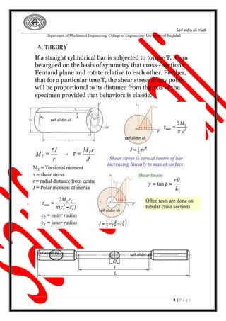
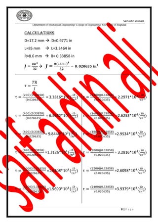
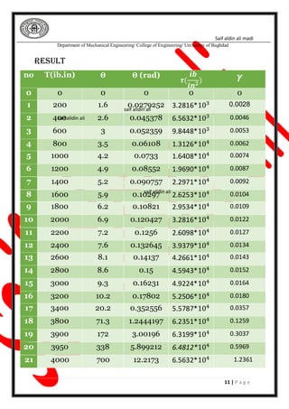
Saif aldin ali madi
Department of Mechanical Engineering/ College of Engineering/ University of Baghdad
1 | P a g e
[MECHANICS OF MATERIALS Laboratory II]
University of Baghdad
Name: - Saif Al-din Ali -B-
Saif aldin ali madi
Department of Mechanical Engineering/ College of Engineering/ University of Baghdad
2 | P a g e
TABLE OF CONTENTS
ABSTRACT........................................................................1
OBJECTIVE........................................................................2
INTRODUCTION...............................................................3
THEORY...........................................................................4
Procedure........................................................................5
Calculations ………………....................................................6
DISCUSSION ....................................................................7
Saif aldin ali madi
Department of Mechanical Engineering/ College of Engineering/ University of Baghdad
3 | P a g e
Name of Experiment: torsion test
1. ABSTRACT
The objective of this experiment is to study the linearly elastic behavior
of metallic material under a torsion test. Torsion test measures the
strength of any material against maximum twisting forces. During this
experiment, a failure testing is done to our testing material which is a
steel. This failure testing involves twisting the material until it breaks
which helps demonstrates how materials undergo during testing
condition by measuring the applied torque with respect to the angle of
twist, the shear modulus, shear stress
At the limit of proportionality. The shear modulus of elasticity G and
Poisson's Ratio are determined for the specimen using torsional stress-
strain relationship from the data collected during the experiment. The
fraction surface of our material at the end of the experiment is used to
stablish characteristics of the material,
2. OBJECTIVE
To conduct torsion test on mild steel a cast iron specimens to find out
modulus of rigidity and the shear stress at yield of the materials
3. INTRODUCTION
Torsion is a variation of shear Torsion is a
variation of shear, Torsion occurs when any
shaft is subjected to a torque. This is true
whether the shaft is rotating (such as drive
shafts on engines, motors and turbines) or
stationary (such as with a bolt or screw). The
torque makes the shaft twist and one end
rotates relative to the other inducing shear
stress on any cross section. Failure might occur
due to shear alone or because the shear is
accompanied by stretching or bending
saif alidin ali
saif alidin ali
Saif aldin ali madi
Department of Mechanical Engineering/ College of Engineering/ University of Baghdad
4 | P a g e
4. THEORY
If a straight cylindrical bar is subjected to torque T, it can
be argued on the basis of symmetry that cross - sections
Fernand plane and rotate relative to each other. Further,
that for a particular true T, the shear stress at any point
will be proportional to its distance from the axis of the
specimen provided that behaviors is classic.
saif alidin ali saif alidin ali
saif alidin ali
saif alidin ali
saif alidin ali
Saif aldin ali madi
Department of Mechanical Engineering/ College of Engineering/ University of Baghdad
5 | P a g e
1 The relationship between modulus of rigidity (G) and modulus of
elasticity (E) is
𝑮 = 𝑬 ∕ 𝟐( 𝟏 + 𝝂)
2 - The relationship between tensile stress (𝜎) and shear stress (𝜏)
at yield point
𝝉 𝒚 = 𝟎. 𝟓𝝈 𝒚
saif alidin ali
saif alidin ali
saif alidin ali
saif alidin ali
Saif aldin ali madi
Department of Mechanical Engineering/ College of Engineering/ University of Baghdad
6 | P a g e
5. Procedure
1) The first step is to determine the measurements of twist
that should be applied to the specimen, so that about 10
statements are obtained before the outer fibers reach the
elastic limit.
2) Measure the specimen, make the estimate and choose
your increment of twist. Attach the torsion meter to the
specimen set in the machine and apply a small twist and
torque to the specimen. Set the zeros for twist
measurement on the torsion meter and at the machine
head.
3) Apply increment of twist and measure torque applied
at each increment as well as twist from the torsion meter
and rotation of machine head. Never reverse the direction
of twisting.
4) When the limit of proportionality has been removed
remove the torsion meter to avoid damage to it during
later stages of the experiment. Continue with experiment
using rotation of the machine head as the measure of
twist. Rotation of the machine head can be interpreted as
twist for the gauge length from a comparison of reading in
the elastic region. Table of experimental reading and
theoretical results
saif alidin ali
saif alidin ali
Saif aldin ali madi
Department of Mechanical Engineering/ College of Engineering/ University of Baghdad
7 | P a g e
6. Calculations and results
The data in the compulsion
no T(ib.in) Ө
0 0 0
1 200 1.6
2 400 2.6
3 600 3
4 800 3.5
5 1000 4.2
6 1200 4.9
7 1400 5.2
8 1600 5.9
9 1800 6.2
10 2000 6.9
11 2200 7.2
12 2400 7.6
13 2600 8.1
14 2800 8.6
15 3000 9.3
16 3200 10.2
17 3400 20.2
18 3800 71.3
19 3900 172
20 3950 338
21 4000 700
saif alidin ali
saif alidin ali
saif alidin ali
Saif aldin ali madi
Department of Mechanical Engineering/ College of Engineering/ University of Baghdad
8 | P a g e
Calculations
D=17.2 mm  D=0.6771 in
L=85 mm  L=3.3464 in
R=8.6 mm  R= 0.33858 in
𝑱 =
𝝅𝑫 𝟒
𝟑𝟐
 𝑱 =
𝝅(0.6771 ) 𝟒
𝟑𝟐
= 𝟎. 𝟎𝟐𝟎𝟔𝟑𝟓 𝒊𝒏 𝟒
𝜏 =
𝑇𝑅
𝐽
τ =
(200)(0.33858)
(0.020635)
= 3.2816*103
(
𝑖𝑏
𝑖𝑛2
)
τ =
(400)(0.33858)
(0.020635)
= 6.5632*103(
𝑖𝑏
𝑖𝑛2
)
τ =
(600)(0.33858)
(0.020635)
= 9.8448*103(
𝑖𝑏
𝑖𝑛2)
τ =
(800)(0.33858)
(0.020635)
=1.3126*104(
𝑖𝑏
𝑖𝑛2
)
τ =
(1000)(0.33858)
(0.020635)
=1.6408*104(
𝑖𝑏
𝑖𝑛2
)
τ =
(1200)(0.33858)
(0.020635)
=1.9690*104
(
𝑖𝑏
𝑖𝑛2)
τ =
(1400)(0.33858)
(0.020635)
= 2.2971*104
(
𝑖𝑏
𝑖𝑛2
)
τ =
(1600)(0.33858)
(0.020635)
=2.6253*104(
𝑖𝑏
𝑖𝑛2
)
τ =
(1800)(0.33858)
(0.020635)
=2.9534*104(
𝑖𝑏
𝑖𝑛2)
τ =
(2000)(0.33858)
(0.020635)
= 3.2816*104(
𝑖𝑏
𝑖𝑛2)
τ =
(2200)(0.33858)
(0.020635)
=2.6098*104(
𝑖𝑏
𝑖𝑛2
)
τ =
(2400)(0.33858)
(0.020635)
=3.9379*104
(
𝑖𝑏
𝑖𝑛2)
Saif aldin ali madi
Department of Mechanical Engineering/ College of Engineering/ University of Baghdad
9 | P a g e
𝜏 =
(2600)(0.33858)
(0.020635)
=4.2661*104
(
𝑖𝑏
𝑖𝑛2)
𝜏 =
(2800)(0.33858)
(0.020635)
=4.5943*104
(
𝑖𝑏
𝑖𝑛2
)
𝜏 =
(3000)(0.33858)
(0.020635)
= 4.9224*104
(
𝑖𝑏
𝑖𝑛2)
𝜏 =
(3200)(0.33858)
(0.020635)
= 5.2506*104(
𝑖𝑏
𝑖𝑛2)
𝜏 =
(3400)(0.33858)
(0.020635)
= 5.5787*104(
𝑖𝑏
𝑖𝑛2
)
𝜏 =
(3800)(0.33858)
(0.020635)
= 6.2351*104
(
𝑖𝑏
𝑖𝑛2)
𝜏 =
(3900)(0.33858)
(0.020635)
= 6.3199*104
(
𝑖𝑏
𝑖𝑛2)
𝜏 =
(3950)(0.33858)
(0.020635)
= 6.4812*104(
𝑖𝑏
𝑖𝑛2
)
𝜏 =
(4000)(0.33858)
(0.020635)
=6.5632*104(
𝑖𝑏
𝑖𝑛2
)
Saif aldin ali madi
Department of Mechanical Engineering/ College of Engineering/ University of Baghdad
10 | P a g e
𝛄 =
𝑹𝜽
𝒍
1. 𝛄 =
(𝟎.𝟑𝟑𝟖𝟓𝟖 )(𝟎.𝟎𝟐𝟕𝟗𝟐𝟓𝟐)
(𝟑.𝟑𝟒𝟔𝟒 )
=0.0028
2. 𝛄 =
(𝟎.𝟑𝟑𝟖𝟓𝟖 )(𝟎.𝟎𝟒𝟓𝟑𝟕𝟖)
(𝟑.𝟑𝟒𝟔𝟒 )
=0.0046
3. 𝛄 =
(𝟎.𝟑𝟑𝟖𝟓𝟖 )(𝟎.𝟎𝟓𝟐𝟑𝟓𝟗)
(𝟑.𝟑𝟒𝟔𝟒 )
=0.0053
4. 𝛄 =
(𝟎.𝟑𝟑𝟖𝟓𝟖 )(𝟎.𝟎𝟔𝟏𝟎𝟖)
(𝟑.𝟑𝟒𝟔𝟒 )
=0.0062
5. 𝛄 =
(𝟎.𝟑𝟑𝟖𝟓𝟖 )(𝟎.𝟎𝟕𝟑𝟑)
(𝟑.𝟑𝟒𝟔𝟒 )
=0.0074
6. 𝛄 =
(𝟎.𝟑𝟑𝟖𝟓𝟖 )(𝟎.𝟎𝟖𝟓𝟓𝟐)
(𝟑.𝟑𝟒𝟔𝟒 )
=0.0087
7. 𝛄 =
(𝟎.𝟑𝟑𝟖𝟓𝟖 )(𝟎.𝟎𝟗𝟎𝟕𝟓𝟕)
(𝟑.𝟑𝟒𝟔𝟒 )
=0.0092
8. 𝛄 =
(𝟎.𝟑𝟑𝟖𝟓𝟖 )(𝟎.𝟏𝟎𝟐𝟗𝟕)
(𝟑.𝟑𝟒𝟔𝟒 )
=0.0104
9. 𝛄 =
(𝟎.𝟑𝟑𝟖𝟓𝟖 )(𝟎.𝟏𝟎𝟖𝟐𝟏)
(𝟑.𝟑𝟒𝟔𝟒 )
=0.0109
10.𝛄 =
(𝟎.𝟑𝟑𝟖𝟓𝟖 )(𝟎.𝟏𝟐𝟎𝟒𝟐𝟕)
(𝟑.𝟑𝟒𝟔𝟒 )
=0.0122
11.𝛄 =
(𝟎.𝟑𝟑𝟖𝟓𝟖 )(𝟎.𝟏𝟐𝟓𝟔)
(𝟑.𝟑𝟒𝟔𝟒 )
= 0.0127
12.𝛄 =
(𝟎.𝟑𝟑𝟖𝟓𝟖 )(𝟎.𝟏𝟑𝟐𝟔𝟒𝟓)
(𝟑.𝟑𝟒𝟔𝟒 )
=0.0134
13.𝛄 =
(𝟎.𝟑𝟑𝟖𝟓𝟖 )(𝟎.𝟏𝟒𝟏𝟑𝟕)
(𝟑.𝟑𝟒𝟔𝟒 )
=0.0143
14.𝛄 =
(𝟎.𝟑𝟑𝟖𝟓𝟖 )(𝟎.𝟏𝟓)
(𝟑.𝟑𝟒𝟔𝟒 )
=0.0152
15.𝛄 =
(𝟎.𝟑𝟑𝟖𝟓𝟖 )(𝟎.𝟏𝟔𝟐𝟑𝟏)
(𝟑.𝟑𝟒𝟔𝟒 )
=0.0164
16.𝛄 =
(𝟎.𝟑𝟑𝟖𝟓𝟖 )(𝟎.𝟏𝟕𝟖𝟎𝟐)
(𝟑.𝟑𝟒𝟔𝟒 )
=0.0180
17.𝛄 =
(𝟎.𝟑𝟑𝟖𝟓𝟖 )(𝟎.𝟑𝟓𝟐𝟓𝟓𝟔)
(𝟑.𝟑𝟒𝟔𝟒 )
=0.0357
18.𝛄 =
(𝟎.𝟑𝟑𝟖𝟓𝟖 )(𝟏.𝟐𝟒𝟒𝟒𝟏𝟗𝟕)
(𝟑.𝟑𝟒𝟔𝟒 )
= 0.1259
19.𝛄 =
(𝟎.𝟑𝟑𝟖𝟓𝟖 )(𝟑.𝟎𝟎𝟏𝟗𝟔)
(𝟑.𝟑𝟒𝟔𝟒 )
= 0.3037
20.𝛄 =
(𝟎.𝟑𝟑𝟖𝟓𝟖 )(𝟓.𝟖𝟗𝟗𝟐𝟏𝟐)
(𝟑.𝟑𝟒𝟔𝟒 )
= 0.5969
21.𝛄 =
(𝟎.𝟑𝟑𝟖𝟓𝟖 )(𝟏𝟐.𝟐𝟏𝟕𝟑)
(𝟑.𝟑𝟒𝟔𝟒 )
=1.2361
Saif aldin ali madi
Department of Mechanical Engineering/ College of Engineering/ University of Baghdad
11 | P a g e
Result
no T(ib.in) Ө Ө (rad)
𝝉(
𝒊𝒃
𝒊𝒏 𝟐) 𝜸
0 0 0 0 0 0
1 200 1.6 0.0279252 3.2816*103 0.0028
2 400 2.6 0.045378 6.5632*103 0.0046
3 600 3 0.052359 9.8448*103 0.0053
4 800 3.5 0.06108 1.3126*104 0.0062
5 1000 4.2 0.0733 1.6408*104 0.0074
6 1200 4.9 0.08552 1.9690*104 0.0087
7 1400 5.2 0.090757 2.2971*104 0.0092
8 1600 5.9 0.10297 2.6253*104 0.0104
9 1800 6.2 0.10821 2.9534*104 0.0109
10 2000 6.9 0.120427 3.2816*104 0.0122
11 2200 7.2 0.1256 2.6098*104 0.0127
12 2400 7.6 0.132645 3.9379*104 0.0134
13 2600 8.1 0.14137 4.2661*104 0.0143
14 2800 8.6 0.15 4.5943*104 0.0152
15 3000 9.3 0.16231 4.9224*104 0.0164
16 3200 10.2 0.17802 5.2506*104 0.0180
17 3400 20.2 0.352556 5.5787*104 0.0357
18 3800 71.3 1.2444197 6.2351*104 0.1259
19 3900 172 3.00196 6.3199*104 0.3037
20 3950 338 5.899212 6.4812*104 0.5969
21 4000 700 12.2173 6.5632*104 1.2361
saif alidin ali
saif alidin ali
saif alidin ali
Saif aldin ali madi
Department of Mechanical Engineering/ College of Engineering/ University of Baghdad
12 | P a g e
the scale
0.2/5=0.04  0.04/5=8*10^-3
𝑡𝑎𝑛∅=G=
∆𝜏
∆𝑌
 G=
30000−20000
8∗10−3−7∗10−3
= 10 ∗ 106
𝑮 = 𝑬 ∕ 𝟐( 𝟏 + 𝝂)
10 ∗ 106
=
30167849.505501762
2(1 + 𝑣)
→ 𝒗 = 𝟎. 𝟓𝟎𝟖𝟑𝟗
∑ 𝛾 = 2.466 → 𝑦 = 0.02 ∗ 2.466 = 0.4932
𝜏 𝑦 = 58000
𝝉 𝒚 = 𝟎. 𝟓𝝈 𝒚  𝛔 𝐲 =
𝟓𝟖𝟎𝟎𝟎
𝟎.𝟓
= 𝟏𝟏𝟔𝟎𝟎𝟎 𝑰𝒃/𝒊𝒏 𝟐
0
10000
20000
30000
40000
50000
60000
70000
0 0.2 0.4 0.6 0.8 1 1.2 1.4
τ(ib/in^2)
y
τ&y
saif alidin ali
saif alidin ali
saif alidin ali
Saif aldin ali madi
Department of Mechanical Engineering/ College of Engineering/ University of Baghdad
13 | P a g e
7. DISCUSSION
1. Discuss the shape of fraction in ductile and brittle
materials
0
500
1000
1500
2000
2500
3000
3500
4000
4500
0 100 200 300 400 500 600 700 800
T(ib.in)
Ө
T&Ө
Saif aldin ali madi
Department of Mechanical Engineering/ College of Engineering/ University of Baghdad
14 | P a g e
Fracture mechanisms
• Ductile fracture
– Accompanied by significant plastic deformation
• Brittle fracture
– Little or no plastic deformation
– Catastrophic
– Usually strain is < 5%
Saif aldin ali madi
Department of Mechanical Engineering/ College of Engineering/ University of Baghdad
15 | P a g e
2. what is applications of torture in mechanical equipment
Cardan shaft
Screws
In turbine fans

Torsion test

  • 1.
    Saif aldin alimadi Department of Mechanical Engineering/ College of Engineering/ University of Baghdad 1 | P a g e [MECHANICS OF MATERIALS Laboratory II] University of Baghdad Name: - Saif Al-din Ali -B-
  • 2.
    Saif aldin alimadi Department of Mechanical Engineering/ College of Engineering/ University of Baghdad 2 | P a g e TABLE OF CONTENTS ABSTRACT........................................................................1 OBJECTIVE........................................................................2 INTRODUCTION...............................................................3 THEORY...........................................................................4 Procedure........................................................................5 Calculations ………………....................................................6 DISCUSSION ....................................................................7
  • 3.
    Saif aldin alimadi Department of Mechanical Engineering/ College of Engineering/ University of Baghdad 3 | P a g e Name of Experiment: torsion test 1. ABSTRACT The objective of this experiment is to study the linearly elastic behavior of metallic material under a torsion test. Torsion test measures the strength of any material against maximum twisting forces. During this experiment, a failure testing is done to our testing material which is a steel. This failure testing involves twisting the material until it breaks which helps demonstrates how materials undergo during testing condition by measuring the applied torque with respect to the angle of twist, the shear modulus, shear stress At the limit of proportionality. The shear modulus of elasticity G and Poisson's Ratio are determined for the specimen using torsional stress- strain relationship from the data collected during the experiment. The fraction surface of our material at the end of the experiment is used to stablish characteristics of the material, 2. OBJECTIVE To conduct torsion test on mild steel a cast iron specimens to find out modulus of rigidity and the shear stress at yield of the materials 3. INTRODUCTION Torsion is a variation of shear Torsion is a variation of shear, Torsion occurs when any shaft is subjected to a torque. This is true whether the shaft is rotating (such as drive shafts on engines, motors and turbines) or stationary (such as with a bolt or screw). The torque makes the shaft twist and one end rotates relative to the other inducing shear stress on any cross section. Failure might occur due to shear alone or because the shear is accompanied by stretching or bending saif alidin ali saif alidin ali
  • 4.
    Saif aldin alimadi Department of Mechanical Engineering/ College of Engineering/ University of Baghdad 4 | P a g e 4. THEORY If a straight cylindrical bar is subjected to torque T, it can be argued on the basis of symmetry that cross - sections Fernand plane and rotate relative to each other. Further, that for a particular true T, the shear stress at any point will be proportional to its distance from the axis of the specimen provided that behaviors is classic. saif alidin ali saif alidin ali saif alidin ali saif alidin ali saif alidin ali
  • 5.
    Saif aldin alimadi Department of Mechanical Engineering/ College of Engineering/ University of Baghdad 5 | P a g e 1 The relationship between modulus of rigidity (G) and modulus of elasticity (E) is 𝑮 = 𝑬 ∕ 𝟐( 𝟏 + 𝝂) 2 - The relationship between tensile stress (𝜎) and shear stress (𝜏) at yield point 𝝉 𝒚 = 𝟎. 𝟓𝝈 𝒚 saif alidin ali saif alidin ali saif alidin ali saif alidin ali
  • 6.
    Saif aldin alimadi Department of Mechanical Engineering/ College of Engineering/ University of Baghdad 6 | P a g e 5. Procedure 1) The first step is to determine the measurements of twist that should be applied to the specimen, so that about 10 statements are obtained before the outer fibers reach the elastic limit. 2) Measure the specimen, make the estimate and choose your increment of twist. Attach the torsion meter to the specimen set in the machine and apply a small twist and torque to the specimen. Set the zeros for twist measurement on the torsion meter and at the machine head. 3) Apply increment of twist and measure torque applied at each increment as well as twist from the torsion meter and rotation of machine head. Never reverse the direction of twisting. 4) When the limit of proportionality has been removed remove the torsion meter to avoid damage to it during later stages of the experiment. Continue with experiment using rotation of the machine head as the measure of twist. Rotation of the machine head can be interpreted as twist for the gauge length from a comparison of reading in the elastic region. Table of experimental reading and theoretical results saif alidin ali saif alidin ali
  • 7.
    Saif aldin alimadi Department of Mechanical Engineering/ College of Engineering/ University of Baghdad 7 | P a g e 6. Calculations and results The data in the compulsion no T(ib.in) Ө 0 0 0 1 200 1.6 2 400 2.6 3 600 3 4 800 3.5 5 1000 4.2 6 1200 4.9 7 1400 5.2 8 1600 5.9 9 1800 6.2 10 2000 6.9 11 2200 7.2 12 2400 7.6 13 2600 8.1 14 2800 8.6 15 3000 9.3 16 3200 10.2 17 3400 20.2 18 3800 71.3 19 3900 172 20 3950 338 21 4000 700 saif alidin ali saif alidin ali saif alidin ali
  • 8.
    Saif aldin alimadi Department of Mechanical Engineering/ College of Engineering/ University of Baghdad 8 | P a g e Calculations D=17.2 mm  D=0.6771 in L=85 mm  L=3.3464 in R=8.6 mm  R= 0.33858 in 𝑱 = 𝝅𝑫 𝟒 𝟑𝟐  𝑱 = 𝝅(0.6771 ) 𝟒 𝟑𝟐 = 𝟎. 𝟎𝟐𝟎𝟔𝟑𝟓 𝒊𝒏 𝟒 𝜏 = 𝑇𝑅 𝐽 τ = (200)(0.33858) (0.020635) = 3.2816*103 ( 𝑖𝑏 𝑖𝑛2 ) τ = (400)(0.33858) (0.020635) = 6.5632*103( 𝑖𝑏 𝑖𝑛2 ) τ = (600)(0.33858) (0.020635) = 9.8448*103( 𝑖𝑏 𝑖𝑛2) τ = (800)(0.33858) (0.020635) =1.3126*104( 𝑖𝑏 𝑖𝑛2 ) τ = (1000)(0.33858) (0.020635) =1.6408*104( 𝑖𝑏 𝑖𝑛2 ) τ = (1200)(0.33858) (0.020635) =1.9690*104 ( 𝑖𝑏 𝑖𝑛2) τ = (1400)(0.33858) (0.020635) = 2.2971*104 ( 𝑖𝑏 𝑖𝑛2 ) τ = (1600)(0.33858) (0.020635) =2.6253*104( 𝑖𝑏 𝑖𝑛2 ) τ = (1800)(0.33858) (0.020635) =2.9534*104( 𝑖𝑏 𝑖𝑛2) τ = (2000)(0.33858) (0.020635) = 3.2816*104( 𝑖𝑏 𝑖𝑛2) τ = (2200)(0.33858) (0.020635) =2.6098*104( 𝑖𝑏 𝑖𝑛2 ) τ = (2400)(0.33858) (0.020635) =3.9379*104 ( 𝑖𝑏 𝑖𝑛2)
  • 9.
    Saif aldin alimadi Department of Mechanical Engineering/ College of Engineering/ University of Baghdad 9 | P a g e 𝜏 = (2600)(0.33858) (0.020635) =4.2661*104 ( 𝑖𝑏 𝑖𝑛2) 𝜏 = (2800)(0.33858) (0.020635) =4.5943*104 ( 𝑖𝑏 𝑖𝑛2 ) 𝜏 = (3000)(0.33858) (0.020635) = 4.9224*104 ( 𝑖𝑏 𝑖𝑛2) 𝜏 = (3200)(0.33858) (0.020635) = 5.2506*104( 𝑖𝑏 𝑖𝑛2) 𝜏 = (3400)(0.33858) (0.020635) = 5.5787*104( 𝑖𝑏 𝑖𝑛2 ) 𝜏 = (3800)(0.33858) (0.020635) = 6.2351*104 ( 𝑖𝑏 𝑖𝑛2) 𝜏 = (3900)(0.33858) (0.020635) = 6.3199*104 ( 𝑖𝑏 𝑖𝑛2) 𝜏 = (3950)(0.33858) (0.020635) = 6.4812*104( 𝑖𝑏 𝑖𝑛2 ) 𝜏 = (4000)(0.33858) (0.020635) =6.5632*104( 𝑖𝑏 𝑖𝑛2 )
  • 10.
    Saif aldin alimadi Department of Mechanical Engineering/ College of Engineering/ University of Baghdad 10 | P a g e 𝛄 = 𝑹𝜽 𝒍 1. 𝛄 = (𝟎.𝟑𝟑𝟖𝟓𝟖 )(𝟎.𝟎𝟐𝟕𝟗𝟐𝟓𝟐) (𝟑.𝟑𝟒𝟔𝟒 ) =0.0028 2. 𝛄 = (𝟎.𝟑𝟑𝟖𝟓𝟖 )(𝟎.𝟎𝟒𝟓𝟑𝟕𝟖) (𝟑.𝟑𝟒𝟔𝟒 ) =0.0046 3. 𝛄 = (𝟎.𝟑𝟑𝟖𝟓𝟖 )(𝟎.𝟎𝟓𝟐𝟑𝟓𝟗) (𝟑.𝟑𝟒𝟔𝟒 ) =0.0053 4. 𝛄 = (𝟎.𝟑𝟑𝟖𝟓𝟖 )(𝟎.𝟎𝟔𝟏𝟎𝟖) (𝟑.𝟑𝟒𝟔𝟒 ) =0.0062 5. 𝛄 = (𝟎.𝟑𝟑𝟖𝟓𝟖 )(𝟎.𝟎𝟕𝟑𝟑) (𝟑.𝟑𝟒𝟔𝟒 ) =0.0074 6. 𝛄 = (𝟎.𝟑𝟑𝟖𝟓𝟖 )(𝟎.𝟎𝟖𝟓𝟓𝟐) (𝟑.𝟑𝟒𝟔𝟒 ) =0.0087 7. 𝛄 = (𝟎.𝟑𝟑𝟖𝟓𝟖 )(𝟎.𝟎𝟗𝟎𝟕𝟓𝟕) (𝟑.𝟑𝟒𝟔𝟒 ) =0.0092 8. 𝛄 = (𝟎.𝟑𝟑𝟖𝟓𝟖 )(𝟎.𝟏𝟎𝟐𝟗𝟕) (𝟑.𝟑𝟒𝟔𝟒 ) =0.0104 9. 𝛄 = (𝟎.𝟑𝟑𝟖𝟓𝟖 )(𝟎.𝟏𝟎𝟖𝟐𝟏) (𝟑.𝟑𝟒𝟔𝟒 ) =0.0109 10.𝛄 = (𝟎.𝟑𝟑𝟖𝟓𝟖 )(𝟎.𝟏𝟐𝟎𝟒𝟐𝟕) (𝟑.𝟑𝟒𝟔𝟒 ) =0.0122 11.𝛄 = (𝟎.𝟑𝟑𝟖𝟓𝟖 )(𝟎.𝟏𝟐𝟓𝟔) (𝟑.𝟑𝟒𝟔𝟒 ) = 0.0127 12.𝛄 = (𝟎.𝟑𝟑𝟖𝟓𝟖 )(𝟎.𝟏𝟑𝟐𝟔𝟒𝟓) (𝟑.𝟑𝟒𝟔𝟒 ) =0.0134 13.𝛄 = (𝟎.𝟑𝟑𝟖𝟓𝟖 )(𝟎.𝟏𝟒𝟏𝟑𝟕) (𝟑.𝟑𝟒𝟔𝟒 ) =0.0143 14.𝛄 = (𝟎.𝟑𝟑𝟖𝟓𝟖 )(𝟎.𝟏𝟓) (𝟑.𝟑𝟒𝟔𝟒 ) =0.0152 15.𝛄 = (𝟎.𝟑𝟑𝟖𝟓𝟖 )(𝟎.𝟏𝟔𝟐𝟑𝟏) (𝟑.𝟑𝟒𝟔𝟒 ) =0.0164 16.𝛄 = (𝟎.𝟑𝟑𝟖𝟓𝟖 )(𝟎.𝟏𝟕𝟖𝟎𝟐) (𝟑.𝟑𝟒𝟔𝟒 ) =0.0180 17.𝛄 = (𝟎.𝟑𝟑𝟖𝟓𝟖 )(𝟎.𝟑𝟓𝟐𝟓𝟓𝟔) (𝟑.𝟑𝟒𝟔𝟒 ) =0.0357 18.𝛄 = (𝟎.𝟑𝟑𝟖𝟓𝟖 )(𝟏.𝟐𝟒𝟒𝟒𝟏𝟗𝟕) (𝟑.𝟑𝟒𝟔𝟒 ) = 0.1259 19.𝛄 = (𝟎.𝟑𝟑𝟖𝟓𝟖 )(𝟑.𝟎𝟎𝟏𝟗𝟔) (𝟑.𝟑𝟒𝟔𝟒 ) = 0.3037 20.𝛄 = (𝟎.𝟑𝟑𝟖𝟓𝟖 )(𝟓.𝟖𝟗𝟗𝟐𝟏𝟐) (𝟑.𝟑𝟒𝟔𝟒 ) = 0.5969 21.𝛄 = (𝟎.𝟑𝟑𝟖𝟓𝟖 )(𝟏𝟐.𝟐𝟏𝟕𝟑) (𝟑.𝟑𝟒𝟔𝟒 ) =1.2361
  • 11.
    Saif aldin alimadi Department of Mechanical Engineering/ College of Engineering/ University of Baghdad 11 | P a g e Result no T(ib.in) Ө Ө (rad) 𝝉( 𝒊𝒃 𝒊𝒏 𝟐) 𝜸 0 0 0 0 0 0 1 200 1.6 0.0279252 3.2816*103 0.0028 2 400 2.6 0.045378 6.5632*103 0.0046 3 600 3 0.052359 9.8448*103 0.0053 4 800 3.5 0.06108 1.3126*104 0.0062 5 1000 4.2 0.0733 1.6408*104 0.0074 6 1200 4.9 0.08552 1.9690*104 0.0087 7 1400 5.2 0.090757 2.2971*104 0.0092 8 1600 5.9 0.10297 2.6253*104 0.0104 9 1800 6.2 0.10821 2.9534*104 0.0109 10 2000 6.9 0.120427 3.2816*104 0.0122 11 2200 7.2 0.1256 2.6098*104 0.0127 12 2400 7.6 0.132645 3.9379*104 0.0134 13 2600 8.1 0.14137 4.2661*104 0.0143 14 2800 8.6 0.15 4.5943*104 0.0152 15 3000 9.3 0.16231 4.9224*104 0.0164 16 3200 10.2 0.17802 5.2506*104 0.0180 17 3400 20.2 0.352556 5.5787*104 0.0357 18 3800 71.3 1.2444197 6.2351*104 0.1259 19 3900 172 3.00196 6.3199*104 0.3037 20 3950 338 5.899212 6.4812*104 0.5969 21 4000 700 12.2173 6.5632*104 1.2361 saif alidin ali saif alidin ali saif alidin ali
  • 12.
    Saif aldin alimadi Department of Mechanical Engineering/ College of Engineering/ University of Baghdad 12 | P a g e the scale 0.2/5=0.04  0.04/5=8*10^-3 𝑡𝑎𝑛∅=G= ∆𝜏 ∆𝑌  G= 30000−20000 8∗10−3−7∗10−3 = 10 ∗ 106 𝑮 = 𝑬 ∕ 𝟐( 𝟏 + 𝝂) 10 ∗ 106 = 30167849.505501762 2(1 + 𝑣) → 𝒗 = 𝟎. 𝟓𝟎𝟖𝟑𝟗 ∑ 𝛾 = 2.466 → 𝑦 = 0.02 ∗ 2.466 = 0.4932 𝜏 𝑦 = 58000 𝝉 𝒚 = 𝟎. 𝟓𝝈 𝒚  𝛔 𝐲 = 𝟓𝟖𝟎𝟎𝟎 𝟎.𝟓 = 𝟏𝟏𝟔𝟎𝟎𝟎 𝑰𝒃/𝒊𝒏 𝟐 0 10000 20000 30000 40000 50000 60000 70000 0 0.2 0.4 0.6 0.8 1 1.2 1.4 τ(ib/in^2) y τ&y saif alidin ali saif alidin ali saif alidin ali
  • 13.
    Saif aldin alimadi Department of Mechanical Engineering/ College of Engineering/ University of Baghdad 13 | P a g e 7. DISCUSSION 1. Discuss the shape of fraction in ductile and brittle materials 0 500 1000 1500 2000 2500 3000 3500 4000 4500 0 100 200 300 400 500 600 700 800 T(ib.in) Ө T&Ө
  • 14.
    Saif aldin alimadi Department of Mechanical Engineering/ College of Engineering/ University of Baghdad 14 | P a g e Fracture mechanisms • Ductile fracture – Accompanied by significant plastic deformation • Brittle fracture – Little or no plastic deformation – Catastrophic – Usually strain is < 5%
  • 15.
    Saif aldin alimadi Department of Mechanical Engineering/ College of Engineering/ University of Baghdad 15 | P a g e 2. what is applications of torture in mechanical equipment Cardan shaft Screws In turbine fans