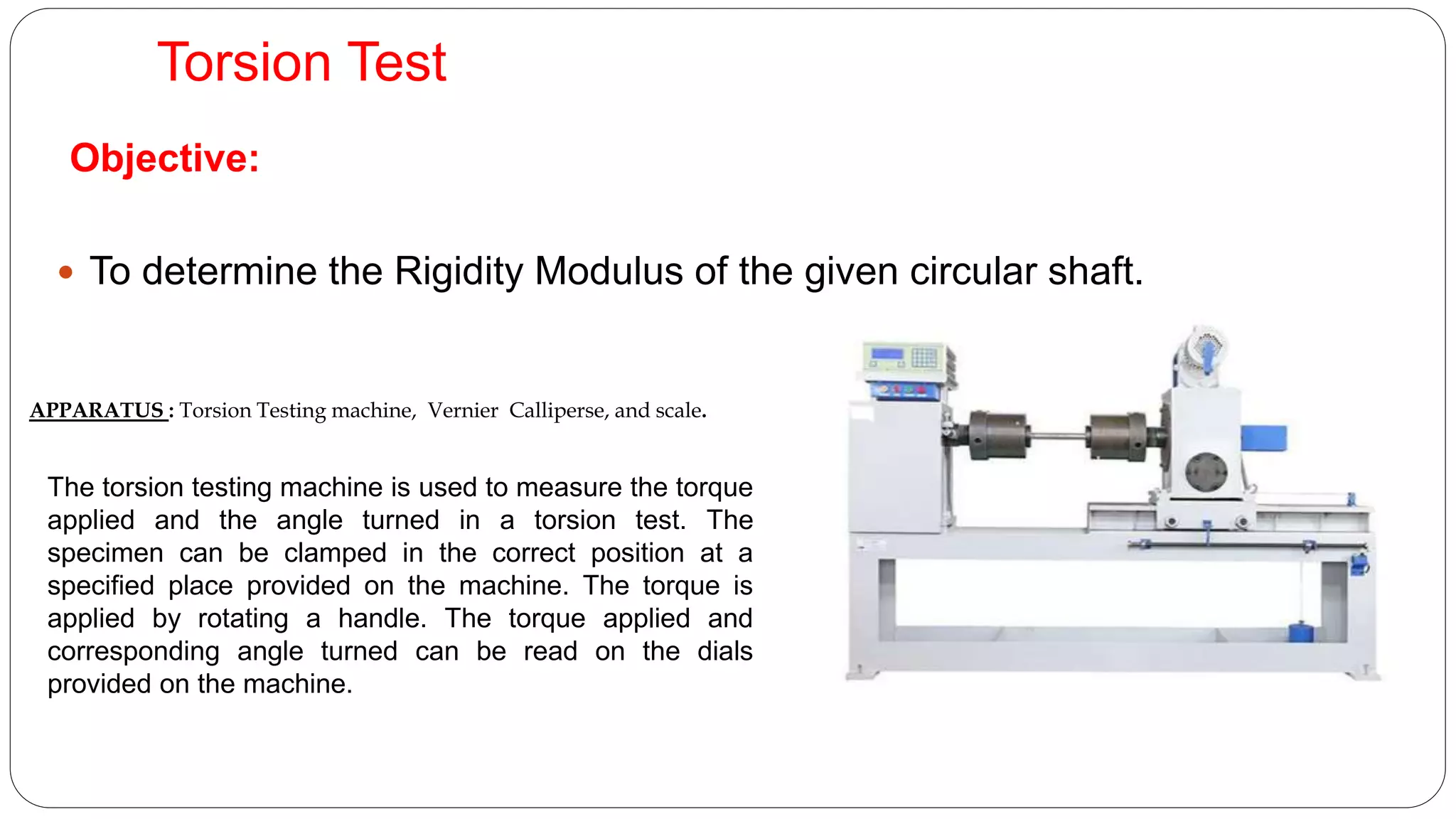
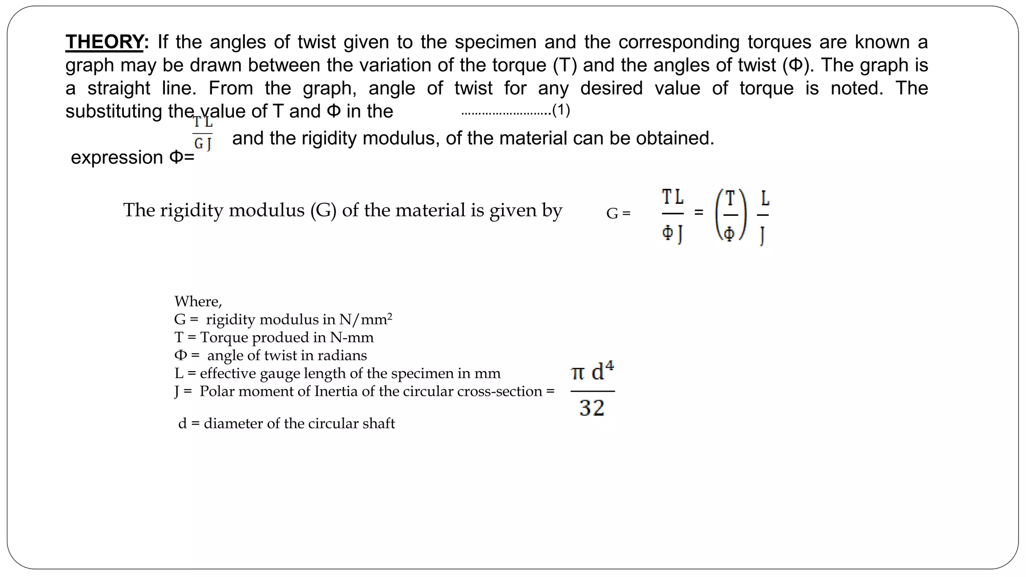
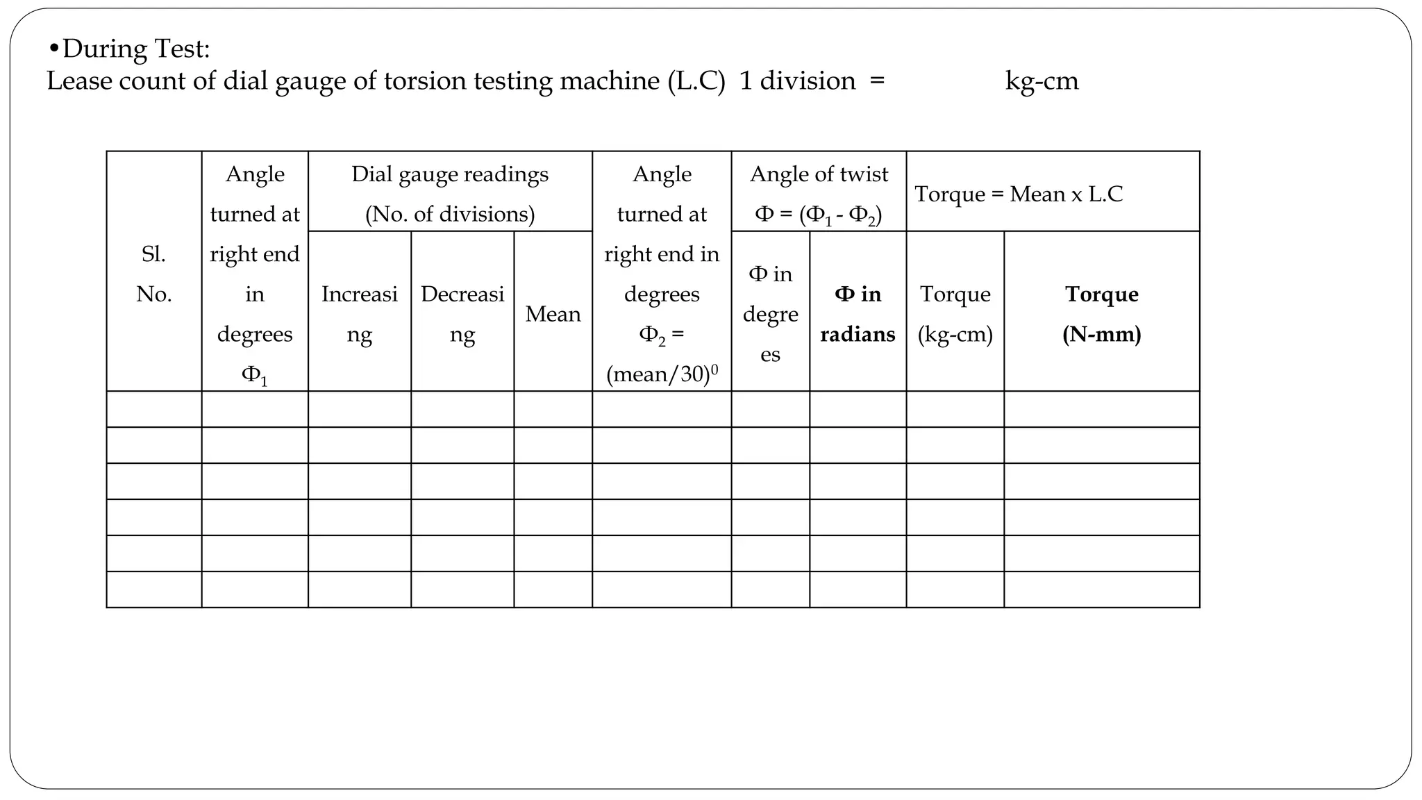
.
Department: Mechanical Engineering
Class: B.Tech. III – Semester
Course: U18ME308 MECHANICS OF SOLIDS LAB
Lecture – 02
Topic to be covered:
After completion of this lecture, the student will be able to,
• Find the torsional Rigidity of given material by
conducting Torsion Test
• Torsion Test
Before We
start the
lecture, Lets
make a quick
review of
the previous
lecture….
• IMPACT test
Objective:
 To determine the Rigidity Modulus of the given circular shaft.
Torsion Test
APPARATUS : Torsion Testing machine, Vernier Calliperse, and scale.
The torsion testing machine is used to measure the torque
applied and the angle turned in a torsion test. The
specimen can be clamped in the correct position at a
specified place provided on the machine. The torque is
applied by rotating a handle. The torque applied and
corresponding angle turned can be read on the dials
provided on the machine.
THEORY: If the angles of twist given to the specimen and the corresponding torques are known a
graph may be drawn between the variation of the torque (T) and the angles of twist (Ф). The graph is
a straight line. From the graph, angle of twist for any desired value of torque is noted. The
substituting the value of T and Ф in the
expression Ф=
and the rigidity modulus, of the material can be obtained.
G =
The rigidity modulus (G) of the material is given by
=
……………………..(1)
Where,
G = rigidity modulus in N/mm2
T = Torque produed in N-mm
Ф = angle of twist in radians
L = effective gauge length of the specimen in mm
J = Polar moment of Inertia of the circular cross-section =
d = diameter of the circular shaft
Procedure
1. Initial adjustments: Before testing, adjust the pendulum weight to suit the capacity of the test piece.
2. To obtain accurate results suitable capacity range for the specimen should be selected with the aid of the
following table
3. Adjust corresponding range on the dial of torsion testing machine with the adjusting knob.
4. The diameter of circular shaft (d) is measured in mm.
5. The polar moment of Inertia (J) is calculated in mm4.
6. The length of the specimen (L) is measured in mm.
7. The specimen is placed on the machine and is gripped properly (already fixed).
8. The gear is adjusted so that, the dial gauge which is used to measure torque is set to zero.
9. The circular disc which is used to measure the amount of twist is adjusted to zero.
Sl.No. Capacity Method of increasing capacity
1 400 Pendulum + A counter weight
2 1000 Pendulum + A + B
3 2000 Pendulum + A + B + C + D
Procedure
1. The gear is rotated in clock wise so that the amount of twist produced in the shaft is 20.
2. The amount of torque produced is measured through the dial gauge in form of divisions.
3. Repeat the test for every 20 increment up to 100 of twist and measure the torque.
4. Then the gear is rotated in opposite direction such that the twist is decreased from 100 to 00 and the
corresponding torque is measured.
5. The torque (T) is calculated in N-mm and the corresponding twist (Ф) is calculated in radians.
6. A graph is drawn between the variation of the torque (T) in N-mm on Y-axis and the angle of twist (Ф) on X-
axis.
7. From the graph, the slope of the line in N-mm/radians is noted.
8. Substitute the ratio in N-mm/radians in equation (1) to obtain the rigidity modulus (G).
Observations
OBSERVATIONS:
•Length of the circular shaft (L) = mm
•Diameter of the circular shaft (d)
Lease count of vernier calipers(L.C.) = mm
Sl.No
Main Scale Reading(MSR)
(mm)
Vernier
Coincidence
(VC)
V.C. x L.C.
(mm)
Total
MSR+(VCxLC)
(mm)
1
2
3
Average
Diameter of circular shaft (d) = mm
•During Test:
Lease count of dial gauge of torsion testing machine (L.C) 1 division = kg-cm
Sl.
No.
Angle
turned at
right end
in
degrees
Ф1
Dial gauge readings
(No. of divisions)
Angle
turned at
right end in
degrees
Ф2 =
(mean/30)0
Angle of twist
Ф = (Ф1 - Ф2)
Torque = Mean x L.C
Increasi
ng
Decreasi
ng
Mean
Ф in
degre
es
Ф in
radians
Torque
(kg-cm)
Torque
(N-mm)
•Length of the circular shaft (L) = mm
•The polar moment of Inertia (J) = mm4.
•From Graph, the ratio = N-mm/radians
CALCULATIONS:
•The rigidity modulus of the material is given by G = =
= N/mm2
RESULT:
The Rigidity Modulus of the given specimen G = N/mm2
Outcomes of the Lecture
You will be able to,
Determine the Torsional Rigidity of given material by conducting Torsion Test

Torsion test 2

  • 1.
    . Department: Mechanical Engineering Class:B.Tech. III – Semester Course: U18ME308 MECHANICS OF SOLIDS LAB Lecture – 02 Topic to be covered: After completion of this lecture, the student will be able to, • Find the torsional Rigidity of given material by conducting Torsion Test • Torsion Test
  • 2.
    Before We start the lecture,Lets make a quick review of the previous lecture…. • IMPACT test
  • 3.
    Objective:  To determinethe Rigidity Modulus of the given circular shaft. Torsion Test APPARATUS : Torsion Testing machine, Vernier Calliperse, and scale. The torsion testing machine is used to measure the torque applied and the angle turned in a torsion test. The specimen can be clamped in the correct position at a specified place provided on the machine. The torque is applied by rotating a handle. The torque applied and corresponding angle turned can be read on the dials provided on the machine.
  • 4.
    THEORY: If theangles of twist given to the specimen and the corresponding torques are known a graph may be drawn between the variation of the torque (T) and the angles of twist (Ф). The graph is a straight line. From the graph, angle of twist for any desired value of torque is noted. The substituting the value of T and Ф in the expression Ф= and the rigidity modulus, of the material can be obtained. G = The rigidity modulus (G) of the material is given by = ……………………..(1) Where, G = rigidity modulus in N/mm2 T = Torque produed in N-mm Ф = angle of twist in radians L = effective gauge length of the specimen in mm J = Polar moment of Inertia of the circular cross-section = d = diameter of the circular shaft
  • 5.
    Procedure 1. Initial adjustments:Before testing, adjust the pendulum weight to suit the capacity of the test piece. 2. To obtain accurate results suitable capacity range for the specimen should be selected with the aid of the following table 3. Adjust corresponding range on the dial of torsion testing machine with the adjusting knob. 4. The diameter of circular shaft (d) is measured in mm. 5. The polar moment of Inertia (J) is calculated in mm4. 6. The length of the specimen (L) is measured in mm. 7. The specimen is placed on the machine and is gripped properly (already fixed). 8. The gear is adjusted so that, the dial gauge which is used to measure torque is set to zero. 9. The circular disc which is used to measure the amount of twist is adjusted to zero. Sl.No. Capacity Method of increasing capacity 1 400 Pendulum + A counter weight 2 1000 Pendulum + A + B 3 2000 Pendulum + A + B + C + D
  • 6.
    Procedure 1. The gearis rotated in clock wise so that the amount of twist produced in the shaft is 20. 2. The amount of torque produced is measured through the dial gauge in form of divisions. 3. Repeat the test for every 20 increment up to 100 of twist and measure the torque. 4. Then the gear is rotated in opposite direction such that the twist is decreased from 100 to 00 and the corresponding torque is measured. 5. The torque (T) is calculated in N-mm and the corresponding twist (Ф) is calculated in radians. 6. A graph is drawn between the variation of the torque (T) in N-mm on Y-axis and the angle of twist (Ф) on X- axis. 7. From the graph, the slope of the line in N-mm/radians is noted. 8. Substitute the ratio in N-mm/radians in equation (1) to obtain the rigidity modulus (G).
  • 7.
    Observations OBSERVATIONS: •Length of thecircular shaft (L) = mm •Diameter of the circular shaft (d) Lease count of vernier calipers(L.C.) = mm Sl.No Main Scale Reading(MSR) (mm) Vernier Coincidence (VC) V.C. x L.C. (mm) Total MSR+(VCxLC) (mm) 1 2 3 Average Diameter of circular shaft (d) = mm
  • 8.
    •During Test: Lease countof dial gauge of torsion testing machine (L.C) 1 division = kg-cm Sl. No. Angle turned at right end in degrees Ф1 Dial gauge readings (No. of divisions) Angle turned at right end in degrees Ф2 = (mean/30)0 Angle of twist Ф = (Ф1 - Ф2) Torque = Mean x L.C Increasi ng Decreasi ng Mean Ф in degre es Ф in radians Torque (kg-cm) Torque (N-mm)
  • 9.
    •Length of thecircular shaft (L) = mm •The polar moment of Inertia (J) = mm4. •From Graph, the ratio = N-mm/radians CALCULATIONS: •The rigidity modulus of the material is given by G = = = N/mm2 RESULT: The Rigidity Modulus of the given specimen G = N/mm2
  • 10.
    Outcomes of theLecture You will be able to, Determine the Torsional Rigidity of given material by conducting Torsion Test