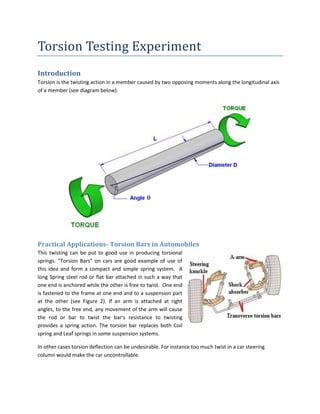
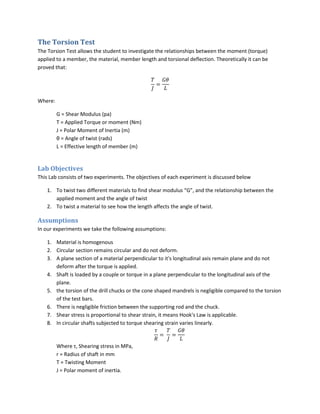
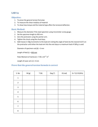
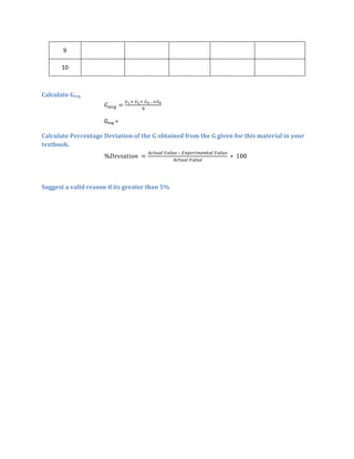
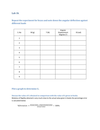
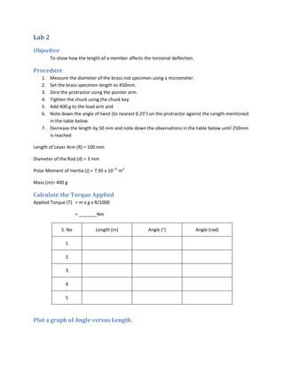
The document describes a torsion testing experiment. It introduces torsion as twisting caused by opposing moments along an axis. Torsion bars in car suspensions are provided as an example application. The objectives of the experiment are to determine the shear modulus G and how applied torque and length affect angular twist. Equipment includes a torsion tester with a loading arm and protractor to measure twist of steel and brass specimens under increasing loads. The experiment aims to verify the torsion formula and measure G for each material by testing specimens of varying lengths and loads.
SAIF ALDIN ALI MADIN
سيف الدين علي ماضي
S96aif@gmail.com
Torsion tesd
MECHANICS OF MATERIALS
The objective of this experiment is to study the linearly elastic behavior
of metallic material under a torsion test. Torsion test measures the
strength of any material against maximum twisting forces. During this
experiment, a failure testing is done to our testing material which is a
steel. This failure testing involves twisting the material until it breaks
which helps demonstrates how materials undergo during testing
condition by measuring the applied torque with respect to the angle of
twist, the shear modulus, shear stress
At the limit of proportionality. The shear modulus of elasticity G and
Poisson's Ratio are determined for the specimen using torsional stressstrain relationship from the data collected during the experiment. The
fraction surface of our material at the end of the experiment is used to
stablish characteristics of the material,
Bending test | MECHANICS OF MATERIALS Laboratory | U.O.B |Saif al-din ali
SAIF A-LDIN ALI
سيف الدين علي ماضي
s96aif@gmail.com
@s96aif
Bending test | MECHANICS OF MATERIALS Laboratory | U.O.B |
The main purpose of the Bend testing is to determine
the ductility, bend strength, fracture strength and
resistance to fracture of the specimen i.e. the
characteristics used to determine whether a material
will fail under pressure and are especially important in
any construction process involving ductile materials
loaded with bending forces.
If a material begins to fracture or completely fractures
during a three or four point bend test it is valid to
assume that the material will fail under a similar in any
application, which may lead to catastrophic failure
To find the values of deflections and bending stresses of the
beam (steel) supported and carrying a concentrated load at
the center in the case of simply or fixed supported and at free
end in cantilever supported case
1 - Cantilever beam
2 - Simply Supported Beam
3. Fixed Beam,
In the material testing laboratory, Tensile test was done on a mild steel specimen as figure 4 to identify the young’s modulus, ultimate tensile strength, yield strength and percentage elongation. The results were as table 1
This is my Lab Report of Tensile Test when I was conducting engineering material lab in Sampoerna University. Feel free to download for a reference.
I know it is not a good report, but I hope this share might help you to find something you need.
Thank you.
Shear and torsion .. it provide good knowledge in engineering mechanics and strength of material. The students who expert in this I am sure that he can perform well in designing mechanical engineering components.
Tensile, Impact and Hardness Testing of Mild SteelGulfam Hussain
The main purpose of this report is to study the mechanical properties and
failure mode of mild steel. Three types of standard tests i.e. tensile test, impact
test, and hardness test were conducted on the standard specimens of mild steel.
From the tests, results were obtained; Tensile strength, Impact strength, and
hardness were calculated. It was observed that Tensile Strength, Impact Strength
and Hardness of MS specimen were 1450.833 N/mm², 29.5 J & 59.25 HRB.
This document is about power transmission system. It's aimed those interested in learning about mechanical engineering and students who are studying various programmes in engineering. This document only deals with power transmission through flat and v-belts.
SAIF ALDIN ALI MADIN
سيف الدين علي ماضي
S96aif@gmail.com
Buckling test
MECHANICS OF MATERIALS
A fundamental condition in all problems is the equilibrium of
internal and external forces. If the system of forces is
disturbed owing to a small displacement of a body, two
principal situations are possible: either the body will return
to its original configuration owing to restoring forces during
displacement, or the body will accelerate farther away from
its original state owing to displacing forces. The latter
situation is termed instable equilibrium.
The instability of structural members subjected to
compressive loading (see Fig. 1(b)) may be regarded as a
mode of failure, even though stress may remain elastic, owing to excessive
deformation and distortion of the structure. This mode of failure is termed
buckling and is prevalent in members for which the transverse dimension is
small compared with the overall length
Fracture mechanics CTOD Crack Tip Opening DisplacementDavalsab M.L
Fracture Mechanics .Whilst the Crack Tip Opening Displacement (CTOD) test was developed for the characterisation of metals it has also been used to determine the toughness of non-metallics such as weldable plastics.
The CTOD test is one such fracture toughness test that is used when some plastic deformation can occur prior to failure - this allows the tip of a crack to stretch and open, hence 'tip opening displacement
In the material testing laboratory, a Charpy impact test was performed on three different types (hot,cold,and steel alloy)of steels testing each variety at four different temperatures (32°C(RT), 100°C,0°C and -22°C ). From results (shown below), we determined that the a transition is from ductile failures to brittle failures
This document gives the class notes of Unit-8: Torsion of circular shafts and elastic stability of columns. Subject: Mechanics of materials.
Syllabus contest is as per VTU, Belagavi, India.
Notes Compiled By: Hareesha N Gowda, Assistant Professor, DSCE, Bengaluru-78.
1. Torsion Testing Experiment
Introduction
Torsion is the twisting action in a member caused by two opposing moments along the longitudinal axis
of a member (see diagram below).
Practical Applications- Torsion Bars in Automobiles
This twisting can be put to good use in producing torsional
springs. “Torsion Bars” on cars are good example of use of
this idea and form a compact and simple spring system. A
long Spring steel rod or flat bar attached in such a way that
one end is anchored while the other is free to twist. One end
is fastened to the frame at one end and to a suspension part
at the other (see Figure 2). If an arm is attached at right
angles, to the free end, any movement of the arm will cause
the rod or bar to twist the bar's resistance to twisting
provides a spring action. The torsion bar replaces both Coil
spring and Leaf springs in some suspension systems.
In other cases torsion deflection can be undesirable. For instance too much twist in a car steering
column would make the car uncontrollable.
2. Give any other application of studying torsion?
_____________________________________________________________________________________
_____________________________________________________________________________________
_____________________________________________________________________________________
3. The Torsion Test
The Torsion Test allows the student to investigate the relationships between the moment (torque)
applied to a member, the material, member length and torsional deflection. Theoretically it can be
proved that:
Where:
G = Shear Modulus (pa)
T = Applied Torque or moment (Nm)
J = Polar Moment of Inertia (m)
θ = Angle of twist (rads)
L = Effective length of member (m)
Lab Objectives
This Lab consists of two experiments. The objectives of each experiment is discussed below
1. To twist two different materials to find shear modulus “G”, and the relationship between the
applied moment and the angle of twist
2. To twist a material to see how the length affects the angle of twist.
Assumptions
In our experiments we take the following assumptions:
1. Material is homogenous
2. Circular section remains circular and do not deform.
3. A plane section of a material perpendicular to it's longitudinal axis remain plane and do not
deform after the torque is applied.
4. Shaft is loaded by a couple or torque in a plane perpendicular to the longitudinal axis of the
plane.
5. the torsion of the drill chucks or the cone shaped mandrels is negligible compared to the torsion
of the test bars.
6. There is negligible friction between the supporting rod and the chuck.
7. Shear stress is proportional to shear strain, it means Hook's Law is applicable.
8. In circular shafts subjected to torque shearing strain varies linearly.
Where τ, Shearing stress in MPa,
r = Radius of shaft in mm
T = Twisting Moment
J = Polar moment of inertia.
4. G = Modulus of rigidity.
θ = Angle of Twist
L = Length of the specimen
Safety Warning:
Ensure that the chucks are as tight as possible to avoid slipping.
The Equipment
The device allows the fundamental relationships of elastic deformation associated with torsion to be
measured and investigated. It is called torsion tester. In this experiment a load is applied to different
test bars and the resulting deformation measured..
The equipment consists of a loading arm with a protractor the is allowed to pivot freely and torsionally
fixed end, which can be moved up and down to give various effective lengths. Drill type chucks at each
end grip the specimen.
Accessories Provided
1. Measuring Tape
2. 2 Specimen Rods (Steel, Brass)
3. Micrometer Screw Guage
4. Weight Hanger
5. Total 50 weights of 10g each
6. Chuck key
5. Reference Material
Some Additional Information:
Shear Moduli:
Steel = 79.6 GPa
Brass = 38.0 GPa
Nominal specimen diameter = 3 mm
for a circular cross section
Where:
D = Diameter of a section
6. LAB 1a
Objective:
1. To prove the general torsion formulae
2. To measure the shear modulus of material
3. To show how torque and the material type affect the torsional deflection.
Basic Method:
1. Measure the diameter if the steel specimen using micrometer screw gauge.
2. Set the specimen length to 450 mm.
3. Zero the protractor using the pointer arm.
4. Tighten the chuck using the chuck keys.
5. Add masses in 50g increments to the load arm noting the angle of twist (to the nearest 0.25°) on
the protractor until either the load arm hits the end stop or a maximum load of 500 g is used.
Diameter of specimen rod (d) = 3 mm
Length of Rod (L) = 450 mm
Polar Moment of Inertia (J) = 7.95 x 10⁻¹² m4
Length of Lever arm (r) = 0.1m
Prove that the general torsion formula is correct
S. No M (g) T (N) Deg (°) Θ (rad) G= TL/J θ (GPa)
1
2
3
4
5
6
7
8
7. 9
10
Calculate Gavg
Gavg =
Calculate Percentage Deviation of the G obtained from the G given for this material in your
textbook.
–
Suggest a valid reason if its greater than 5%
8. Lab 1b
Repeat the experiment for brass and note down the angular deflection against
different loads
Angular
S. No M (g) T (N) Displacement Θ (rad)
Degrees (°)
1
2
3
4
5
6
7
8
9
Plot a graph to determine G.
Discuss the value of G obtained in comparison with the value of G given in books.
Modulus of Rigidity obtained is very much close to the actual value given in books the percentage error
is calculated below
–
9. After this experiment, explain how you will determine the selection of rod if you are
constrained by the length, maximum possible deflection and maximum loading torque.
10. Lab 2
Objective
To show how the length of a member affects the torsional deflection.
Procedure
1. Measure the diameter of the brass rod specimen using a micrometer.
2. Set the brass specimen length to 450mm.
3. Zero the protractor using the pointer arm.
4. Tighten the chuck using the chuck key.
5. Add 400 g to the load arm and
6. Note down the angle of twist (to nearest 0.25°) on the protractor against the Length mentioned
in the table below
7. Decrease the length by 50 mm and note down the observations in the table below until 250mm
is reached
Length of Lever Arm (R) = 100 mm
Diameter of the Rod (d) = 3 mm
Polar Moment of Inertia (J) = 7.95 x 10⁻¹² m4
Mass (m)= 400 g
Calculate the Torque Applied
Applied Torque (T) = m x g x R/1000
= _______Nm
S. No Length (m) Angle (°) Angle (rad)
1
2
3
4
5
Plot a graph of Angle versus Length.
11. What do you observe about the relationship of the graph?
Determine G using the Graph