1. Team Gravity Light developed a low torque, high rpm power train to transmit power from an input shaft to an output shaft via gears in order to power an LED light.
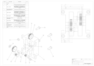
2. The power train used helical gears to transfer power from the input shaft to a middle shaft, and spur gears to transfer power from the middle shaft to the output shaft.
3. The power train achieved its desired output of 810 rpm with a 9:1 speed ratio, and allowed the team members to improve their engineering skills over the course of the project.