Download to read offline


![20
0 0
3822 3822
0 0
0
500
1000
1500
2000
2500
3000
3500
4000
4500
y
[in.]
x [in.]
torque diagram](https://image.slidesharecdn.com/machinedesigngearboxdesignmahamadjawhar-220425215917/75/machine-design-gear-box-design-mahamad-jawhar-pdf-20-2048.jpg)
![21
101 101
647 647
-1742 -1742
0
-2000
-1500
-1000
-500
0
500
1000
y
[in.]
x [in.]
shear force diagram
0
202
3275
3922
2180
0
0
500
1000
1500
2000
2500
3000
3500
4000
4500
y
[in.]
x [in.]
moment diagram(x -z)](https://image.slidesharecdn.com/machinedesigngearboxdesignmahamadjawhar-220425215917/75/machine-design-gear-box-design-mahamad-jawhar-pdf-21-2048.jpg)
![22
354 354
155.28 155.25
-714.22 -714.22
0
-800
-600
-400
-200
0
200
400
600
y
[in.]
x [in.]
shear force diagram(x -y)
0
708
1446
887
0
0
200
400
600
800
1000
1200
1400
1600
y
[in.]
x [in.]
moment diagram(x -y)
0
736
3580
4236
2354
0
0
500
1000
1500
2000
2500
3000
3500
4000
4500
y
[in.]
x [in.]
moment diagram(x -y)](https://image.slidesharecdn.com/machinedesigngearboxdesignmahamadjawhar-220425215917/75/machine-design-gear-box-design-mahamad-jawhar-pdf-22-2048.jpg)


![33
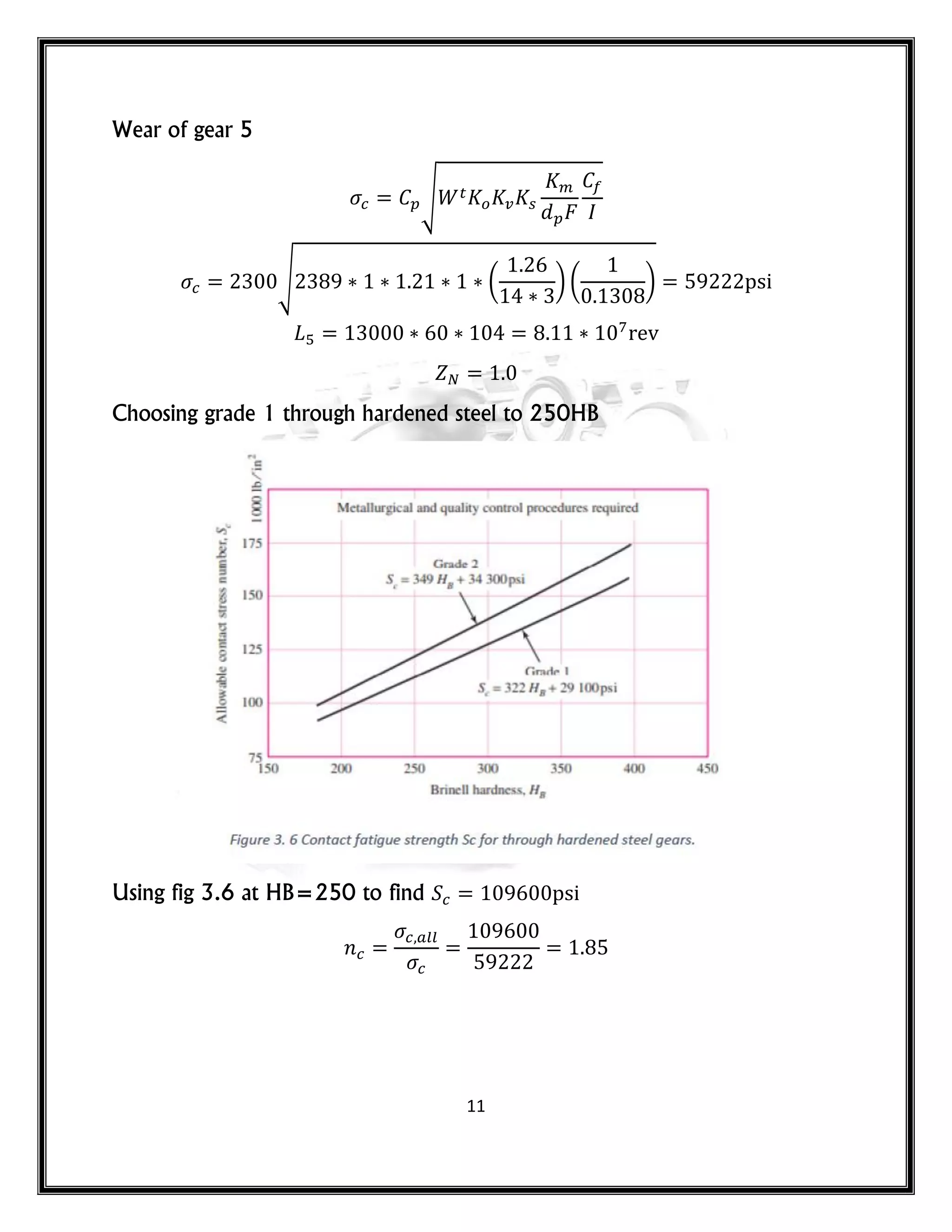
The von Mises maximum stress is :
𝑚 𝑥′= [( 𝑚 + )2 + 3( 𝑚 + )2]1⁄2
*(
𝑘 ( 𝑚 )
) (
𝑘 𝑠( 𝑚 )
) +
To check for yielding, Eq. 30 is compared to the yield strength, then
𝑛𝑦 =
Note: for a quick conservative check, the sum of alternating stress and the midrange
stress is always greater or equal to the maximum stress therefore, the results will be
conservative.
Therefore,
𝑛𝑦
𝑠𝑦 𝑠𝑦
𝑛𝑦 = 3](https://image.slidesharecdn.com/machinedesigngearboxdesignmahamadjawhar-220425215917/75/machine-design-gear-box-design-mahamad-jawhar-pdf-33-2048.jpg)


![42
Y P P
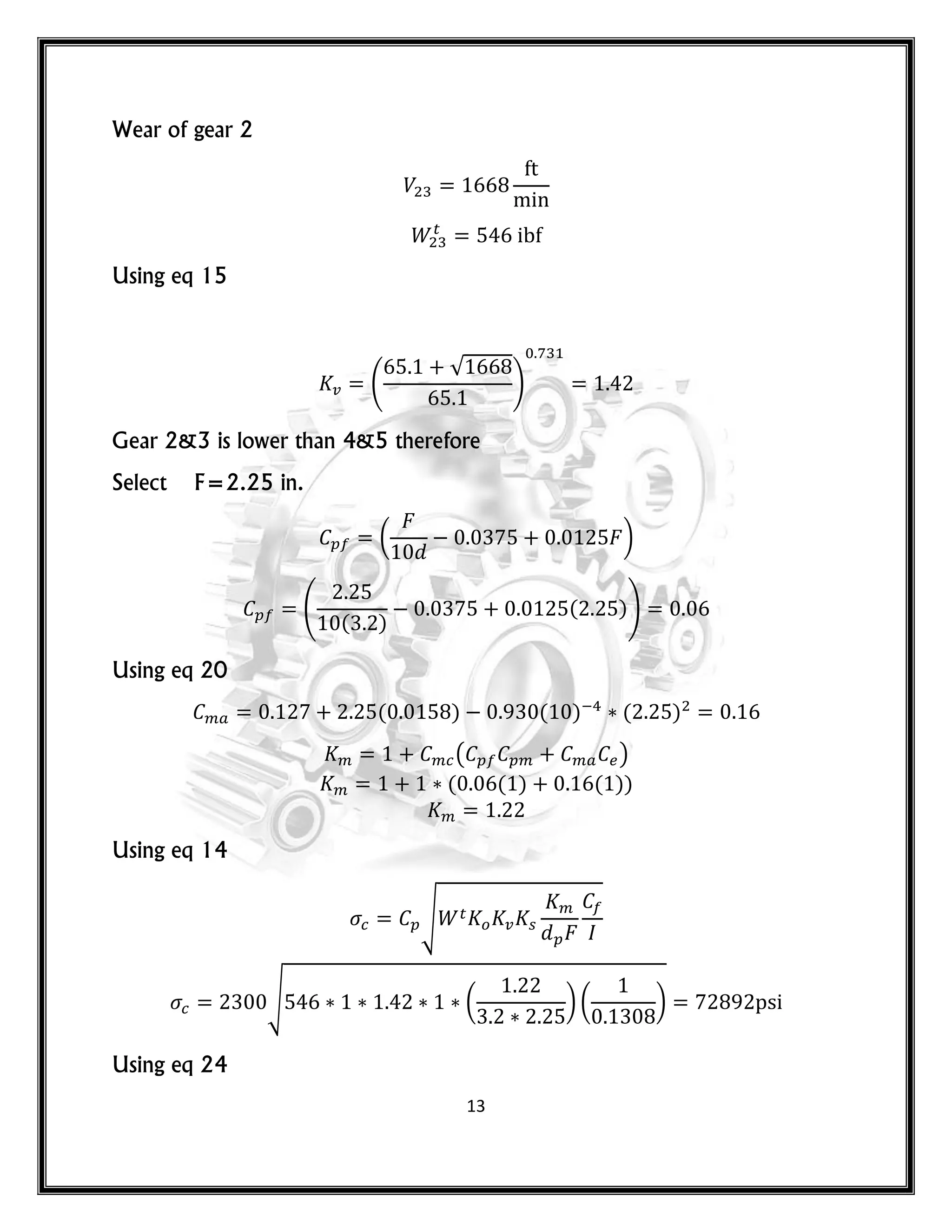
Shoulder
X
RA RB
A D G H I J M B
n
Previous sectio
Next section
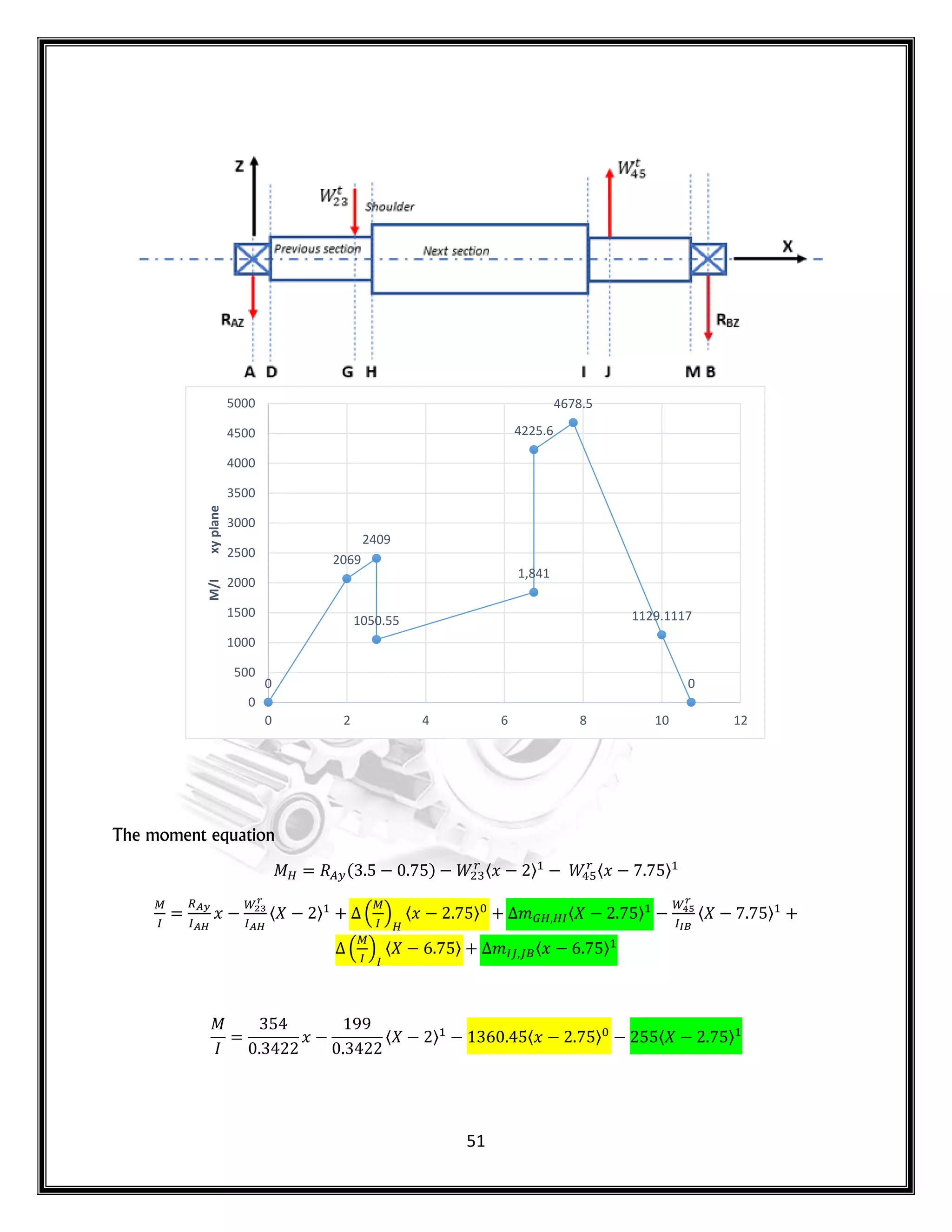
Figure 4. 11 A stepped shaft subjected to concentrated loads.
Divide the moment equation by the second moment of area (I) of the previous section
of the shaft. The equation becomes.
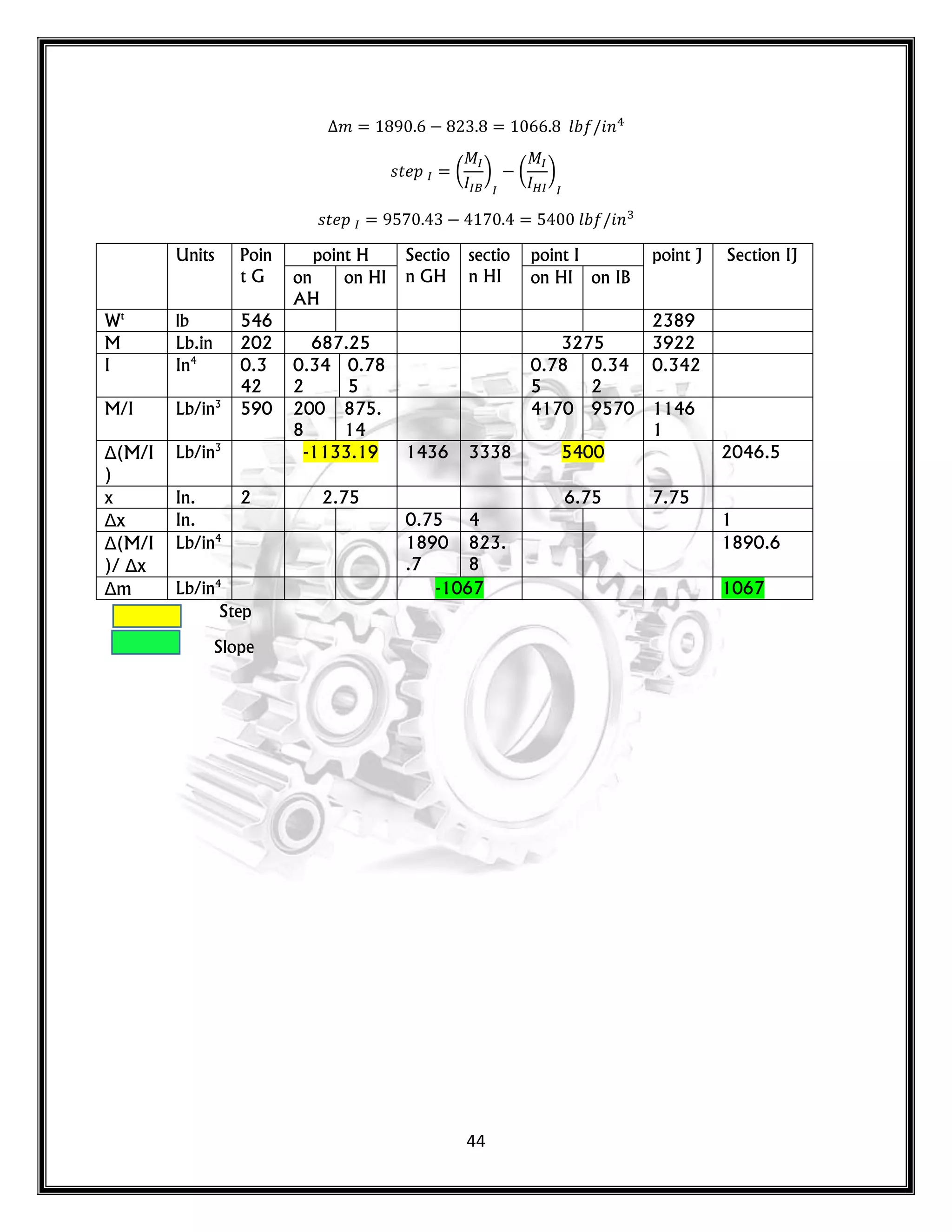
At the distance (𝑥 ) where the shoulder exists, add a step change in ( ⁄ ) as
follows:
𝑠𝑡 𝑝 . /
𝑠𝑡 𝑝 ( ) ( )
At the distance (𝑥 ) where the shoulder exists, add a ramp change in ( ⁄ ) as
follows:
𝑠𝑙𝑜𝑝 𝑚 [
. /
𝑥
]
𝑚 [
. / . /
𝑥
]
( )
𝑛
( )
𝑛](https://image.slidesharecdn.com/machinedesigngearboxdesignmahamadjawhar-220425215917/75/machine-design-gear-box-design-mahamad-jawhar-pdf-42-2048.jpg)


![47
𝑦 , 𝑥 〈𝑥 〉 〈𝑥 〉 〈𝑥 〉 〈𝑥 〉
〈𝑥 〉 𝑥- 𝑜𝑟 𝑥
𝑦 , 𝑥 〈𝑥 〉 〈𝑥 〉 〈𝑥 〉 〈𝑥 〉
〈𝑥 〉 〈𝑥 〉
𝑥- 𝑜𝑟 𝑥
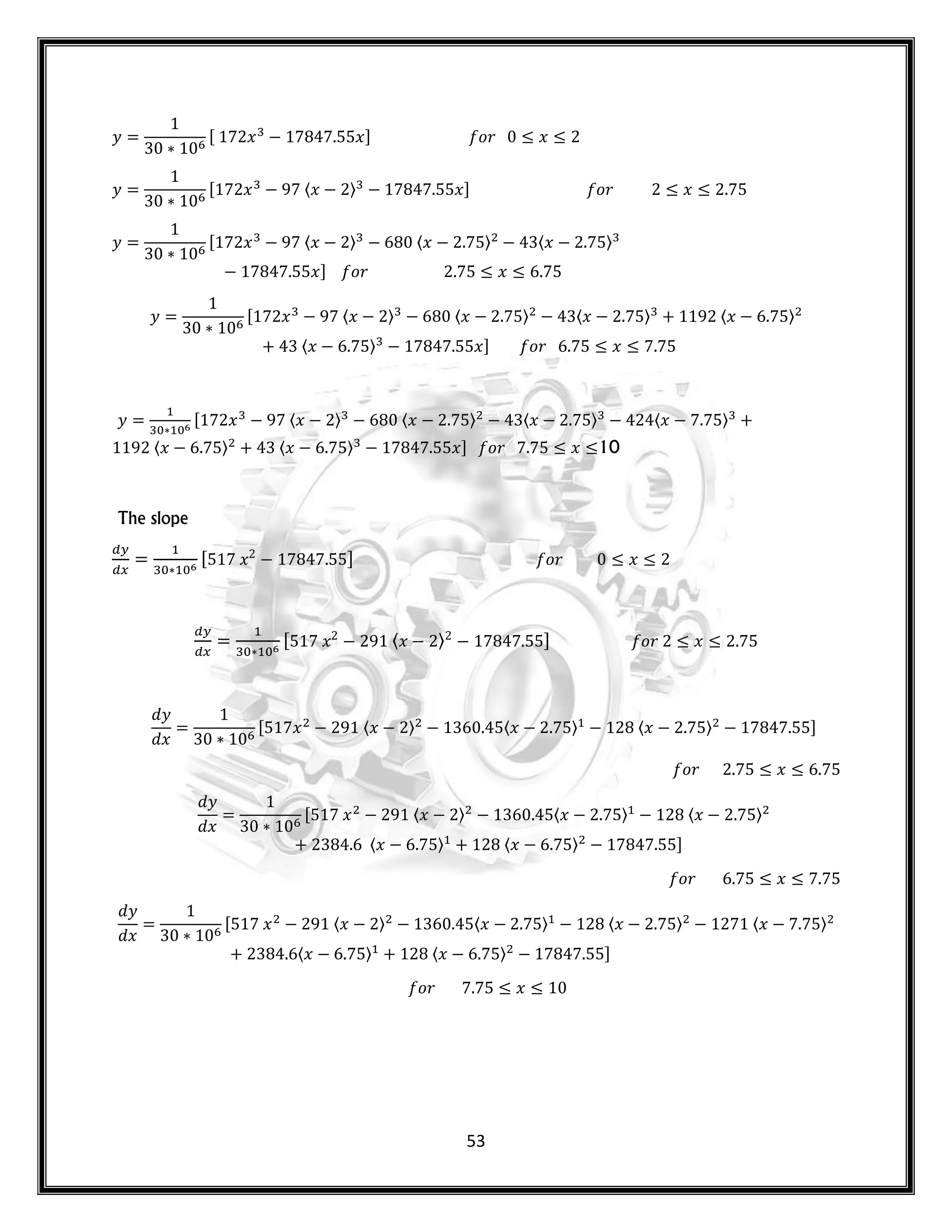
The slope
, 𝑥 - 𝑜𝑟 𝑥
, 𝑥 〈𝑥 〉 - 𝑜𝑟 𝑥
𝑦
𝑥
, 𝑥 〈𝑥 〉 〈𝑥 〉 〈𝑥 〉 -
𝑜𝑟 𝑥
𝑦
𝑥
, 𝑥 〈𝑥 〉 〈𝑥 〉 〈𝑥 〉 〈𝑥 〉
〈𝑥 〉 -
𝑜𝑟 𝑥
𝑦
𝑥
, 𝑥 〈𝑥 〉 〈𝑥 〉 〈𝑥 〉 〈𝑥 〉
〈𝑥 〉 〈𝑥 〉 -
𝑜𝑟 𝑥
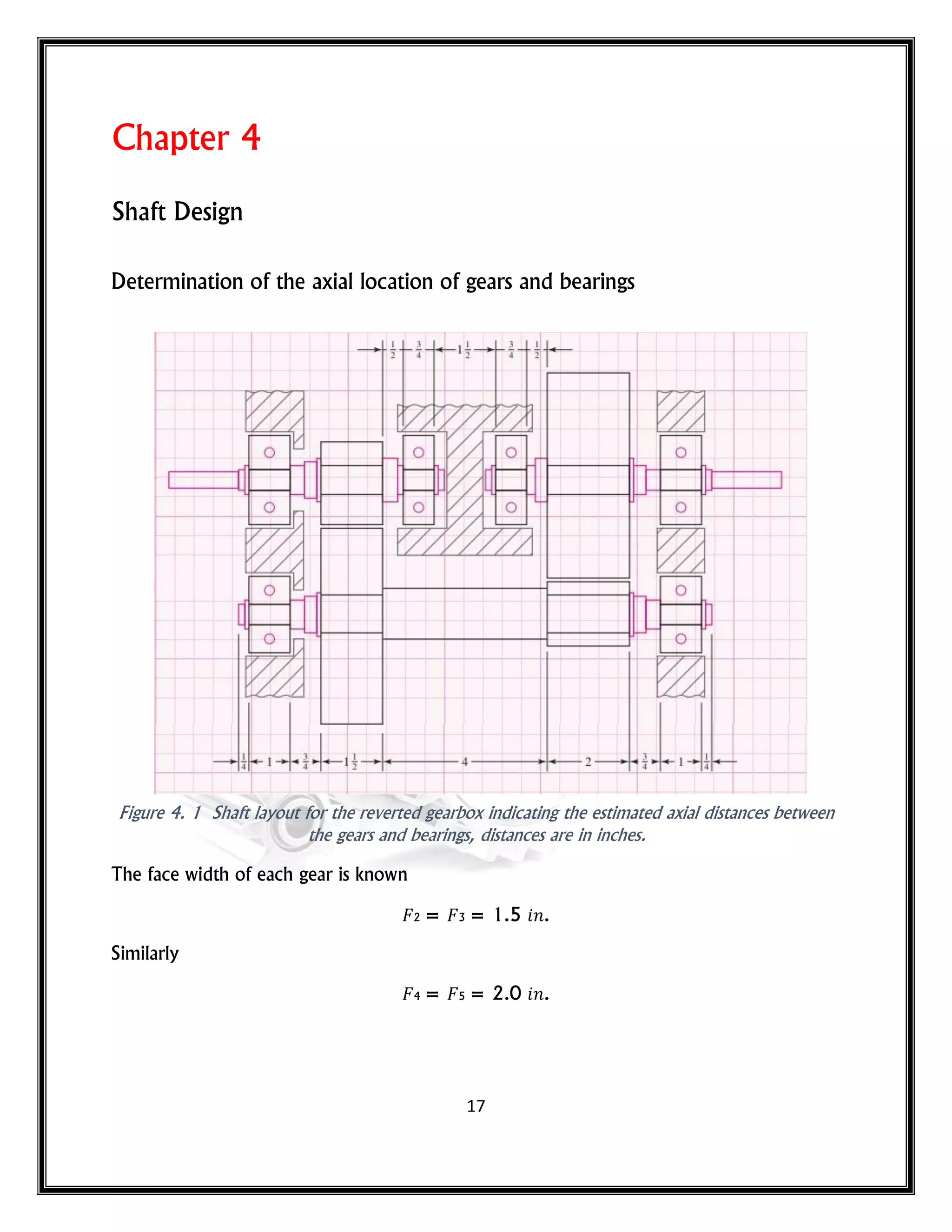
x
[in.]
Point Fittings y
[in.]
dy/dx
[deg.]
0 A Left bearing 0 0.0221
2 G Gear 3 - 0.00076 0.0210
2.75 H Shoulder H - 0.00102
6.75 I Shoulder I - 0.00184
7.75 J Gear 4 - 0.00167 0.0203
10 B Right
Bearing
0 0.0671](https://image.slidesharecdn.com/machinedesigngearboxdesignmahamadjawhar-220425215917/75/machine-design-gear-box-design-mahamad-jawhar-pdf-47-2048.jpg)
![48
𝑠𝑡 𝑝 . /
𝑠𝑡 𝑝 ( ) ( )
At the distance (𝑥 ) where the shoulder exists, add a ramp change in ( ⁄ ) as
follows:
𝑠𝑙𝑜𝑝 𝑚 [
. /
𝑥
]
0
-0.00076
-0.00102
-0.00184
-0.00167
0
-0.0025
-0.002
-0.0015
-0.001
-0.0005
0
y
[in.]
x [in.]
Deflection](https://image.slidesharecdn.com/machinedesigngearboxdesignmahamadjawhar-220425215917/75/machine-design-gear-box-design-mahamad-jawhar-pdf-48-2048.jpg)
![49
𝑚 [
. / . /
𝑥
]
( )
𝑛
( )
𝑛
X-Y plane Shoulder H
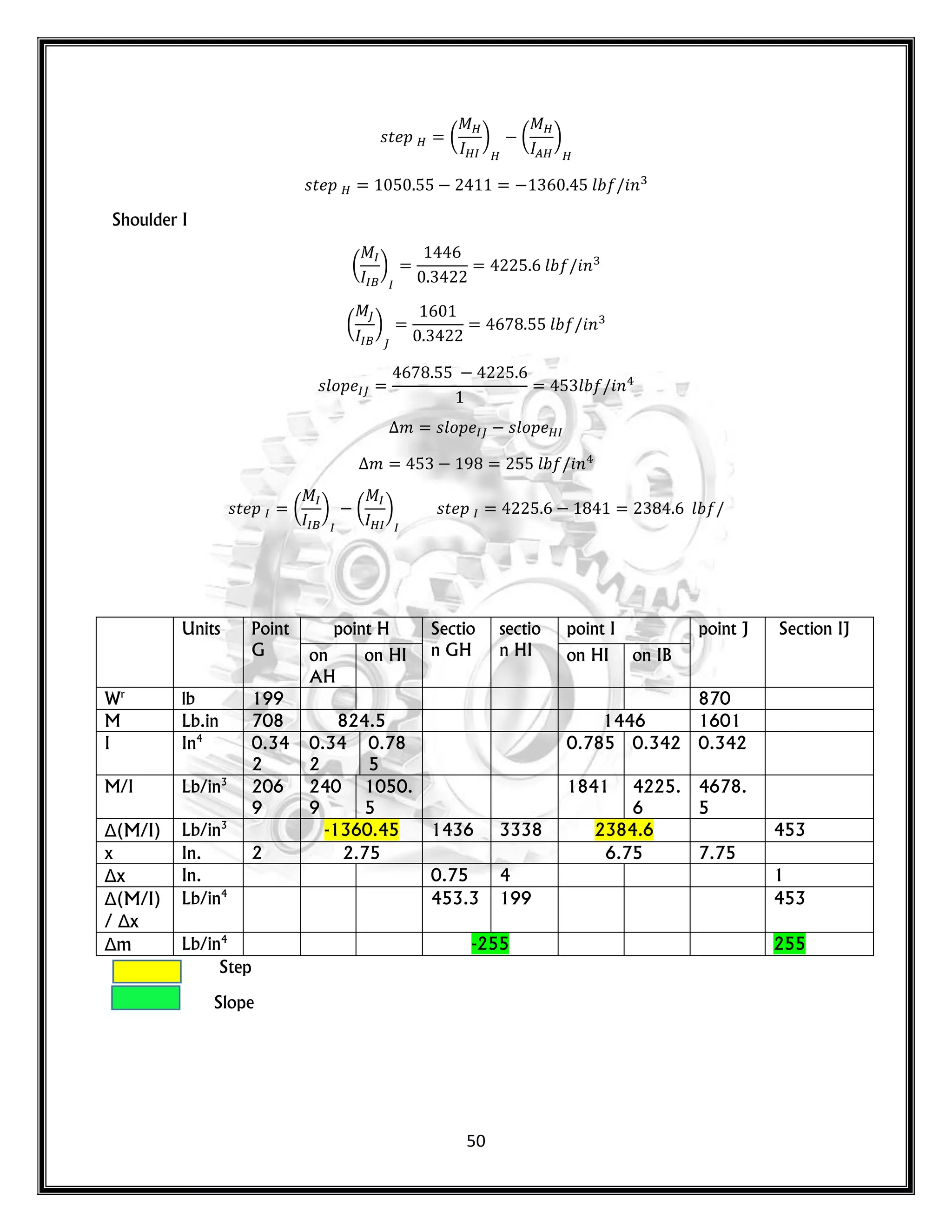
( ) 𝑙 𝑛
( ) ( )
( ) ( ) 𝑙 𝑛
( ) 𝑙 𝑛
𝑠𝑙𝑜𝑝 𝑙 𝑛
( ) 𝑙 𝑛
( ) 𝑙 𝑛
𝑠𝑙𝑜𝑝 𝑙 𝑛
𝑚 𝑠𝑙𝑜𝑝 𝑠𝑙𝑜𝑝
𝑚 𝑙 𝑛](https://image.slidesharecdn.com/machinedesigngearboxdesignmahamadjawhar-220425215917/75/machine-design-gear-box-design-mahamad-jawhar-pdf-49-2048.jpg)

![54
x
[in.]
Point Fittings y
[in.]
dy/dx
[deg.]
0 A Left bearing 0 0.0340
2 G Gear 3 - 0.000114 0.0301
2.75 H Shoulder H - 0.001680
6.75 I Shoulder I - 0.003053
7.75 J Gear 4 - 0.005927 0.00746
10 B Right
Bearing
0 0.00249
0 -0.000114
-0.00168
-0.003053
-0.005927
0
-0.007
-0.006
-0.005
-0.004
-0.003
-0.002
-0.001
0
0.001
y
[in.]
x [in.]
Deflection](https://image.slidesharecdn.com/machinedesigngearboxdesignmahamadjawhar-220425215917/75/machine-design-gear-box-design-mahamad-jawhar-pdf-54-2048.jpg)
![55
The final bearing slope results show
slope
Bearings xz plane
[Deg.]
xy plane
[Deg.]
Total
[Deg.]
Total [rad.]
Left 0.0221 0.0340 0.056 0.000977
Right 0.0671 0.00249 0.068 0.001186](https://image.slidesharecdn.com/machinedesigngearboxdesignmahamadjawhar-220425215917/75/machine-design-gear-box-design-mahamad-jawhar-pdf-55-2048.jpg)
![57
873 873
0
0
100
200
300
400
500
600
700
800
900
1000
y
[in.]
x [in.]
torque diagram (
246 246
301 301
0
0
50
100
150
200
250
300
350
y
[in.]
x [in.]
shear force diagram](https://image.slidesharecdn.com/machinedesigngearboxdesignmahamadjawhar-220425215917/75/machine-design-gear-box-design-mahamad-jawhar-pdf-57-2048.jpg)
![58
0
112.168
490
264
0
0
100
200
300
400
500
600
y
[in.]
x [in.]
moment diagram(x -z)
89 89
-110 -110
0
-150
-100
-50
0
50
100
y
[in.]
x [in.]
shear force diagram(x -y)
0
282.069
490
0
0
100
200
300
400
500
600
y
[in.]
x [in.]
moment diagram(x -y)](https://image.slidesharecdn.com/machinedesigngearboxdesignmahamadjawhar-220425215917/75/machine-design-gear-box-design-mahamad-jawhar-pdf-58-2048.jpg)
![59
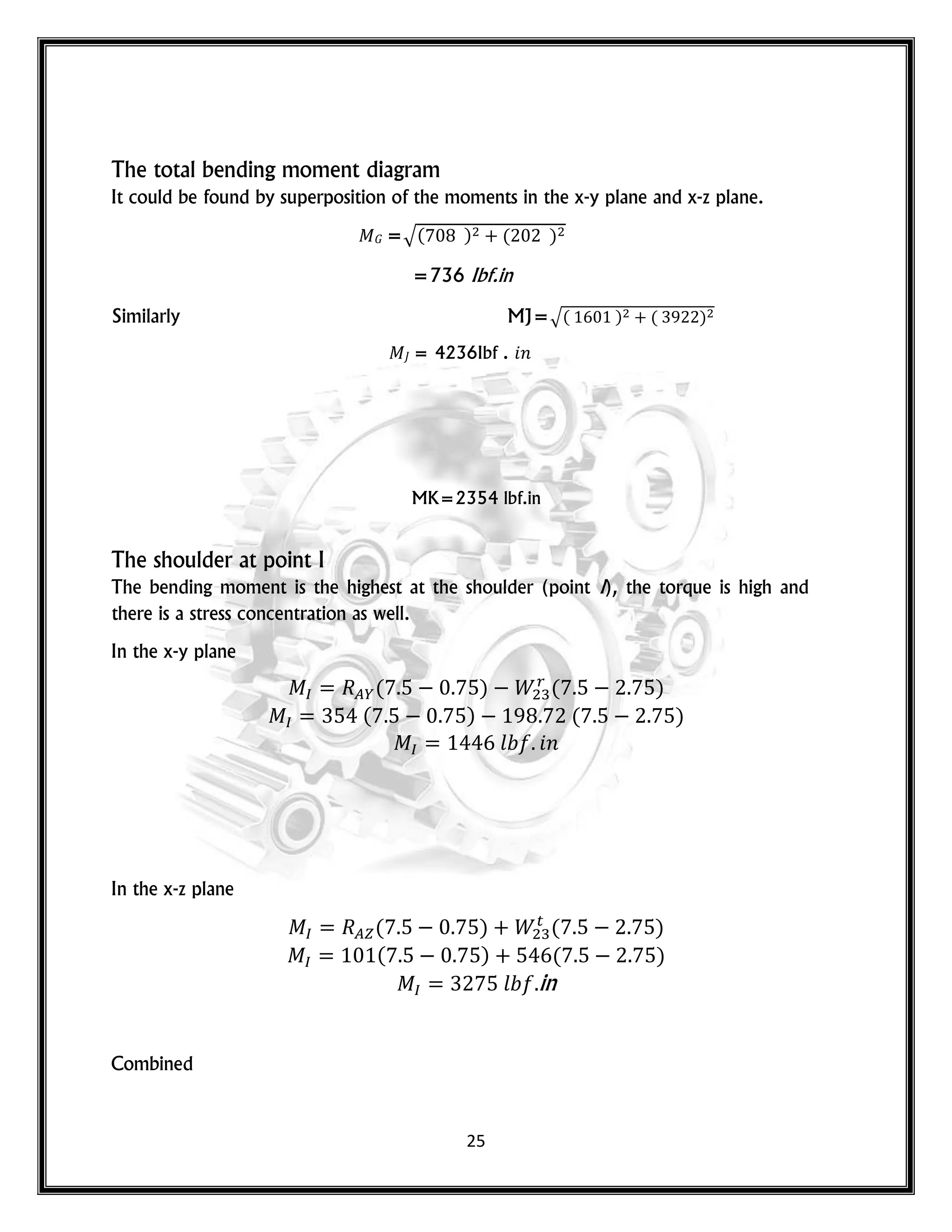
The Shear force and Bending moment diagrams
x-y plane
𝐺 = = 89 𝑙
𝐺 = -
𝐺 = 89 – 199
𝐺 = -110 𝑙
𝑥
( )
𝑙 in
( ) 𝑟
( )
( ) ( )
x-z plane
𝐺 = = -246 𝑙
𝐺 = +
𝐺 = 245 + 546
0
119.366
564.279
515.172
0
0
100
200
300
400
500
600
y
[in.]
x [in.]
moment diagram(x -y)](https://image.slidesharecdn.com/machinedesigngearboxdesignmahamadjawhar-220425215917/75/machine-design-gear-box-design-mahamad-jawhar-pdf-59-2048.jpg)


![65
Check for Yielding
The von Mises maximum stress is :
𝑚 𝑥′= [( 𝑚 + )2 + 3( 𝑚 + )2]1⁄2
*(
𝑘 ( 𝑚 )
) (
𝑘 𝑠( 𝑚 )
) +
𝑛𝑦
𝑠𝑦 𝑠𝑦
= 3.9
The Keyway
From the total bending moment diagram, let the moment at the end of keyway close to
point (I) is
= 390 . 𝑛
Assume that at the bottom of the keyway
= 0.02 ( 𝑠𝑡 𝑛 𝑟 𝑝𝑟𝑜𝑝𝑜𝑟𝑡 𝑜𝑛)
Therefore,
𝑟 =0.02*0.938
𝑟 =0.01876
Using fig. 4.5
𝑡 = 2.49
And using fig. 4.6
𝑞 = 0.58](https://image.slidesharecdn.com/machinedesigngearboxdesignmahamadjawhar-220425215917/75/machine-design-gear-box-design-mahamad-jawhar-pdf-65-2048.jpg)
![72
𝑥 𝑥
( ) ( )
lbf
lbf
16723 16723
0
0
2000
4000
6000
8000
10000
12000
14000
16000
18000
y
[in.]
x [in.]
torque diagram (
1303
395
0
0
200
400
600
800
1000
1200
1400
y
[in.]
x [in.]
shear force diagram](https://image.slidesharecdn.com/machinedesigngearboxdesignmahamadjawhar-220425215917/75/machine-design-gear-box-design-mahamad-jawhar-pdf-72-2048.jpg)
![73
0
2443
0
0
0
500
1000
1500
2000
2500
3000
y
[in.]
x [in.]
moment diagram(x -z)
395 395
-395 -395
0
-500
-400
-300
-200
-100
0
100
200
300
400
500
y
[in.]
x [in.]
shear force diagram(x -y)
0
891
0
0
100
200
300
400
500
600
700
800
900
1000
y
[in.]
x [in.]
moment diagram(x -y)](https://image.slidesharecdn.com/machinedesigngearboxdesignmahamadjawhar-220425215917/75/machine-design-gear-box-design-mahamad-jawhar-pdf-73-2048.jpg)
![74
Figure 4. 3 Freebody diagram, torque, shear force and bending moment diagrams for the shaft.
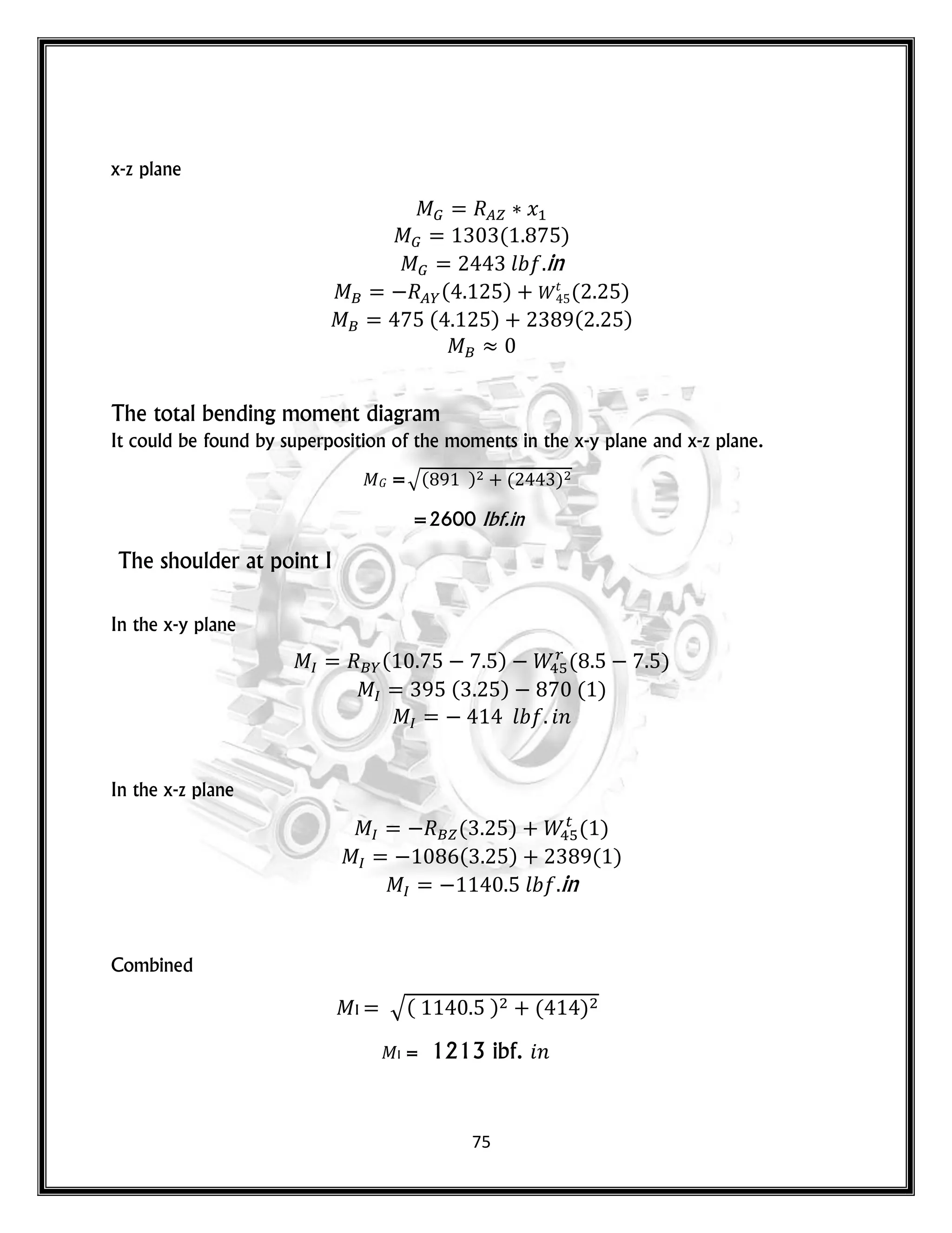
The Shear force and Bending moment diagrams
x-y plane
𝐺 = = 475 𝑙
𝐺 = -
𝐺 = 475 – 870
𝐺 = -395 𝑙
𝑥
( )
𝑙 in
( ) 𝑟
( )
( ) ( )
0
0
0
2600
0
0
500
1000
1500
2000
2500
3000
y
[in.]
x [in.]
moment diagram(x -y)](https://image.slidesharecdn.com/machinedesigngearboxdesignmahamadjawhar-220425215917/75/machine-design-gear-box-design-mahamad-jawhar-pdf-74-2048.jpg)


![80
Check for Yielding
The von Mises maximum stress is :
𝑚 𝑥′= [( 𝑚 + )2 + 3( 𝑚 + )2]1⁄2
*(
𝑘 ( 𝑚 )
) (
𝑘 𝑠( 𝑚 )
) +
𝑛𝑦
= 1.73
The Keyway
= 1320 . 𝑛
Assume that at the bottom of the keyway
= 0.02 ( 𝑠𝑡 𝑛 𝑟 𝑝𝑟𝑜𝑝𝑜𝑟𝑡 𝑜𝑛)
Therefore,
𝑟 =0.02*1.812](https://image.slidesharecdn.com/machinedesigngearboxdesignmahamadjawhar-220425215917/75/machine-design-gear-box-design-mahamad-jawhar-pdf-80-2048.jpg)

![88
=
Assuming a ball bearing with
= 3
And using eq. 5.2 [
( )( ) ⁄
]
= 1 𝑜𝑟 𝑠𝑡 𝑦 𝑙𝑜 𝑠.
[
( ) ⁄
]
10 = 22086ibf
10 = 22086 0.00444
10 = 98 𝑘
Checking this load with SKF bearing catalogue for ball bearings in the vicinity of 1 in.
diameter, as shown in table. 5.1. It sounds that the load is too high for a deep groove ball
bearing. Repeating the load calculation for a roller bearing with](https://image.slidesharecdn.com/machinedesigngearboxdesignmahamadjawhar-220425215917/75/machine-design-gear-box-design-mahamad-jawhar-pdf-88-2048.jpg)
![89
[
( ) ⁄
]
10 = 17266
10 = 17266 0.00444
10 = 76.66 𝑘
Checking this load with SKF bearing catalogue for roller bearings in the vicinity of 1 in.
diameter, as shown in table. 5.2. The tables show that the following roller bearing matches
the load.
= 83𝑘
𝐷=30𝑚𝑚=1.188 in
𝑂𝐷 = 72 𝑚𝑚 = 2.834 𝑛.
= 27 𝑚𝑚 = 1.063 𝑛.](https://image.slidesharecdn.com/machinedesigngearboxdesignmahamadjawhar-220425215917/75/machine-design-gear-box-design-mahamad-jawhar-pdf-89-2048.jpg)
![90
Left bearing selection
Choosing a ball bearing with
= 3
And using eq. 5.2
[
( )( ) ⁄
]
= 1 𝑜𝑟 𝑠𝑡 𝑦 𝑙𝑜 𝑠.
[
( ) ⁄
]
10 = 4316
10 = 4316 0.00444
10 = 19.16𝑘
Searching table 5.1 that gives the specifications of deep groove ball bearings in the proximity
of 1 in bore and applied load of 19.16kN.
The bearings in this category that matches these requirements is SKF 6305.
The left bearing specifications are
𝐷 = 25𝑚𝑚 = 1 𝑛.
𝑂𝐷 = 62 𝑚𝑚 ≈ 2.5 𝑛.
= 17 𝑚𝑚 = 0.67 𝑛.
= 23.4𝑘 = 5270 𝑙 .
𝑜𝑢𝑙 𝑟 𝑚 𝑡 𝑟 = 1.3~1.4 𝑛.
𝑚 𝑥 𝑚𝑢𝑚 𝑙𝑙 𝑡 𝑟 𝑢𝑠 = 0.08 𝑛.
The right bearing bore is 1.1811 in. which is slightly larger than the estimated one. However,
this has no effect of the design since the diameter of the next step of the shaft is 1.4 in. that
provide the required shoulder for the bearing.](https://image.slidesharecdn.com/machinedesigngearboxdesignmahamadjawhar-220425215917/75/machine-design-gear-box-design-mahamad-jawhar-pdf-90-2048.jpg)
![91
Bearing of Gear 2
Left bearing Selection
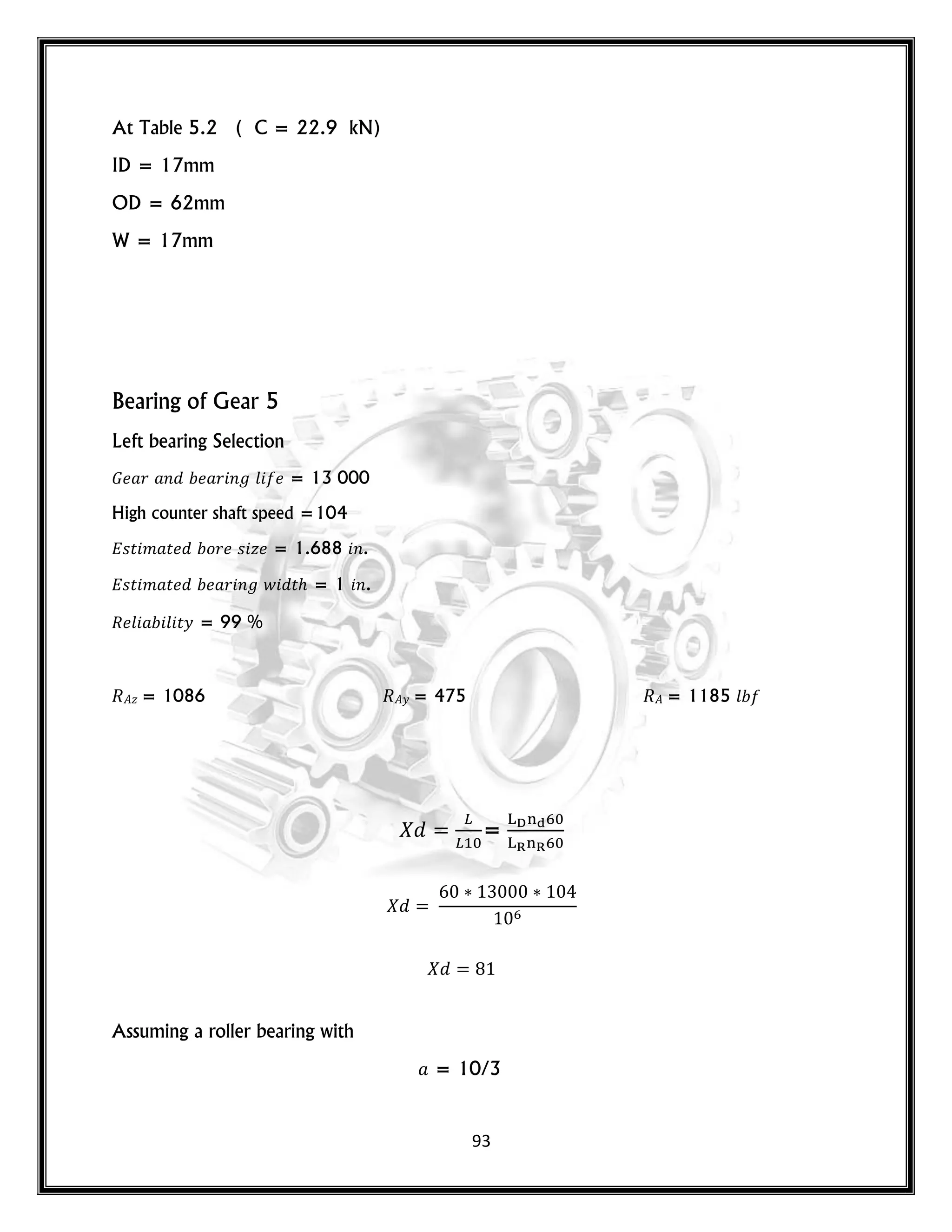
𝐺 𝑟 𝑛 𝑟 𝑛 𝑙 = 13 000
High counter shaft speed =1992 rpm.
𝑠𝑡 𝑚 𝑡 𝑜𝑟 𝑠 𝑧 = 0.750 𝑛.
𝑠𝑡 𝑚 𝑡 𝑟 𝑛 𝑤 𝑡 = 1 𝑛.
𝑙 𝑙 𝑡𝑦 = 99 %
𝑧 = 245 𝑦 = 89 = 260 𝑙
=
Assuming a ball bearing with
= 3
[
( ) ⁄
]
10 = 5491.946
10 = 4988 0.00444
10 = 22.14 𝑘
At Table 5.1 ( C= 26 kN)](https://image.slidesharecdn.com/machinedesigngearboxdesignmahamadjawhar-220425215917/75/machine-design-gear-box-design-mahamad-jawhar-pdf-91-2048.jpg)
![92
ID = 25mm
OD = 62mm
W = 17mm
Right bearing Selection
B𝑧 =301 i B𝑦 = 110 B= 320 𝑙
Assuming a roller bearing with
=
=10/3
[
( ) ⁄
]
10 = 4569 𝑙
10 = 4569 0.00444
10 = 20.28 𝑘](https://image.slidesharecdn.com/machinedesigngearboxdesignmahamadjawhar-220425215917/75/machine-design-gear-box-design-mahamad-jawhar-pdf-92-2048.jpg)
![94
[
( ) ⁄
]
10 = 6975
10 = 6975 0.00444
10 = 31 𝑘
At Table 5.2 ( C= 44.6 kN)
ID = 45mm
OD =75 mm
W = 16mm
Right bearing Selection
B𝑧 = 1086 B𝑦 = 395 𝑙 B = 1155 𝑙
Assuming a roller bearing with
= 10/3
[
( ) ⁄
]
10 = 6798 𝑙
10 = 6798 0.00444
10 = 30.18 𝑘
At Table 5.2 ( C = 44.6 kN)
ID = 45mm
OD = 75mm
W = 16mm](https://image.slidesharecdn.com/machinedesigngearboxdesignmahamadjawhar-220425215917/75/machine-design-gear-box-design-mahamad-jawhar-pdf-94-2048.jpg)
![95
Chapter 6
Key and Keyway Design
For Gear4 & Gear 3.
From the previous data
Bore [in.] Hub length [in.] Torque lbf.in. Safety factor
Gear 3 1.625 1.5
3822 2
Gear 4 1.625 2.0
Using table 6.3 for a square key
Shaft diameter w h Keyway depth
1.625 1 5/8 3/8 3/8 3/16
Choosing key material of 1020 CD steel with 𝑺𝒚 = 𝟓𝟕 𝒌𝒑𝒔𝒊.
The lateral force on the key at the surface of the shaft is:
=
The area prone to bearing stress is
𝑙 𝑙
The bearing stress is](https://image.slidesharecdn.com/machinedesigngearboxdesignmahamadjawhar-220425215917/75/machine-design-gear-box-design-mahamad-jawhar-pdf-95-2048.jpg)
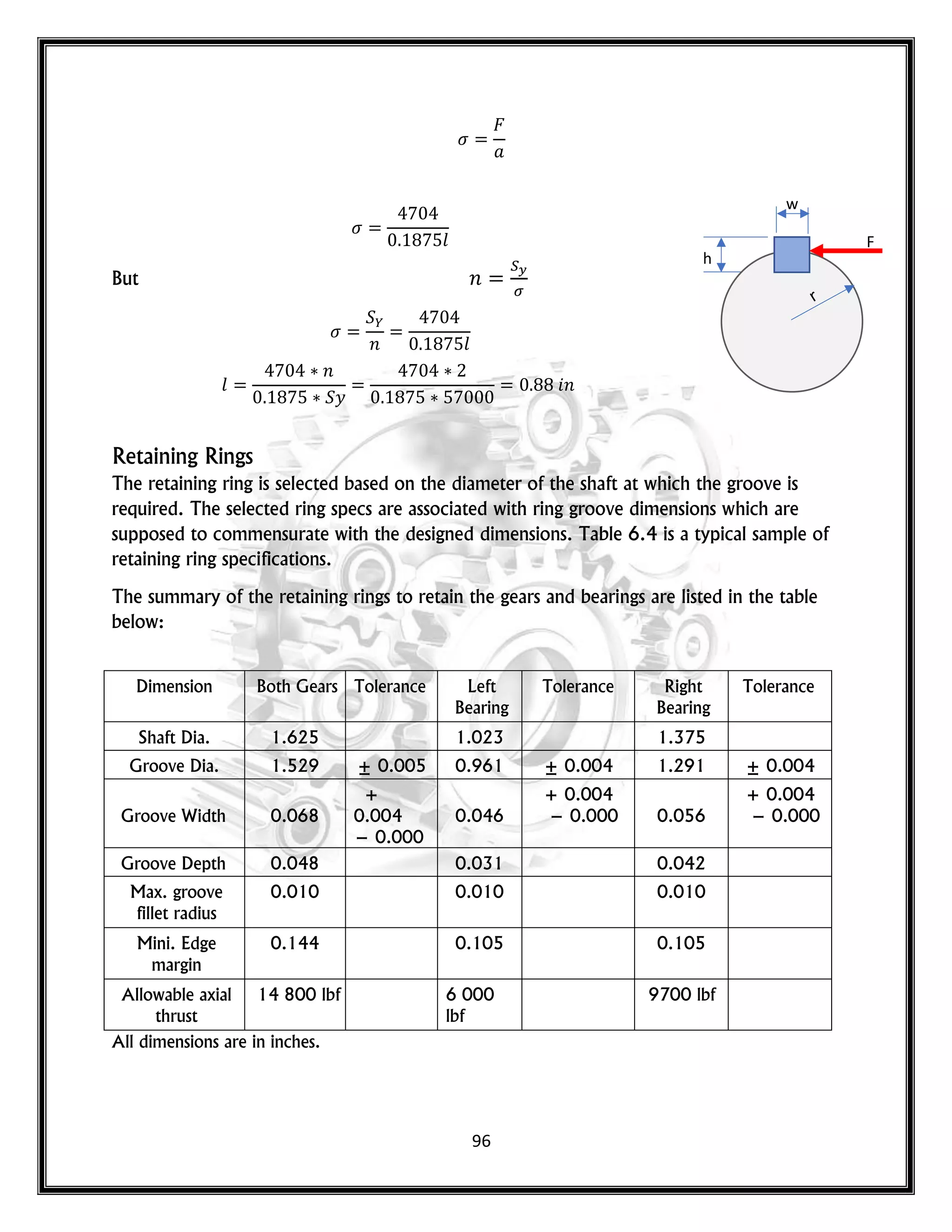
![97
For Gear 2
From the previous data
Bore [in.] Hub length [in.] Torque lbf.in. Safety factor
Gear 2 0.938 1.5 873 2
Using table 6.3 for a square key
Shaft diameter w h Keyway depth
0.938 7.5/8 1/4 1/4 1/8
Choosing key material of 1020 CD steel with 𝑺𝒚 = 𝟓𝟕 𝒌𝒑𝒔𝒊.
The lateral force on the key at the surface of the shaft is:
=
The area prone to bearing stress is
𝑙 𝑙
The bearing stress is
𝑙
But 𝑛
𝑛 𝑙
𝑙
𝑛
𝑦
𝑙 𝑛](https://image.slidesharecdn.com/machinedesigngearboxdesignmahamadjawhar-220425215917/75/machine-design-gear-box-design-mahamad-jawhar-pdf-97-2048.jpg)
![98
For Gear 5
From the previous data
Bore [in.] Hub length [in.] Torque lbf.in. Safety factor
Gear 2 1.812 2 16723 2
Using table 6.3 for a square key
Shaft diameter w h Keyway depth
1.812 1 13/16 1/2 1/2 1/4
Choosing key material of 1045 CD steel with 𝑺𝒚 = 7𝟕 𝒌𝒑𝒔𝒊.
The lateral force on the key at the surface of the shaft is:
=
The area prone to bearing stress is
𝑙 𝑙
The bearing stress is
𝑙
But 𝑛
𝑛
𝑙
𝑛
𝑦
𝑛](https://image.slidesharecdn.com/machinedesigngearboxdesignmahamadjawhar-220425215917/75/machine-design-gear-box-design-mahamad-jawhar-pdf-98-2048.jpg)


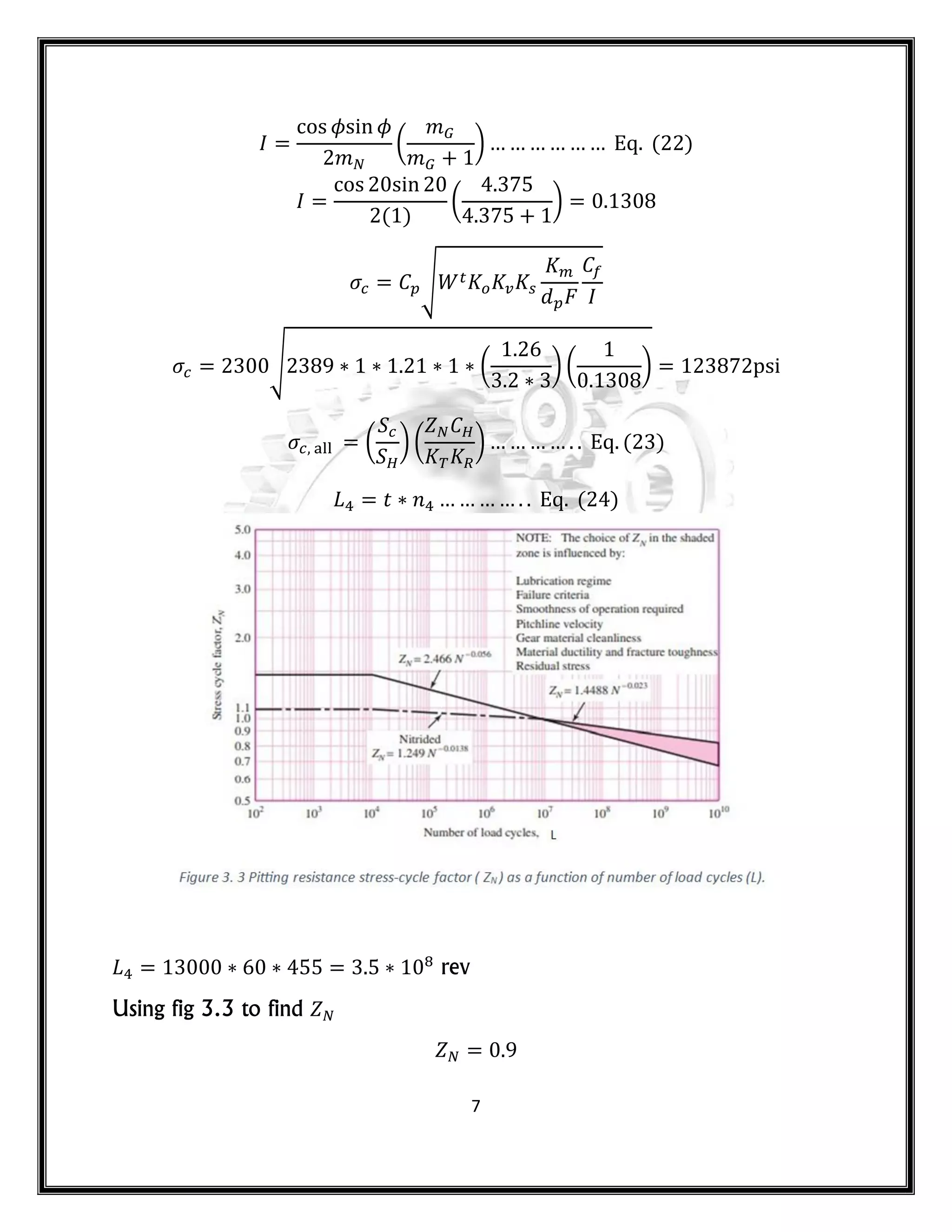
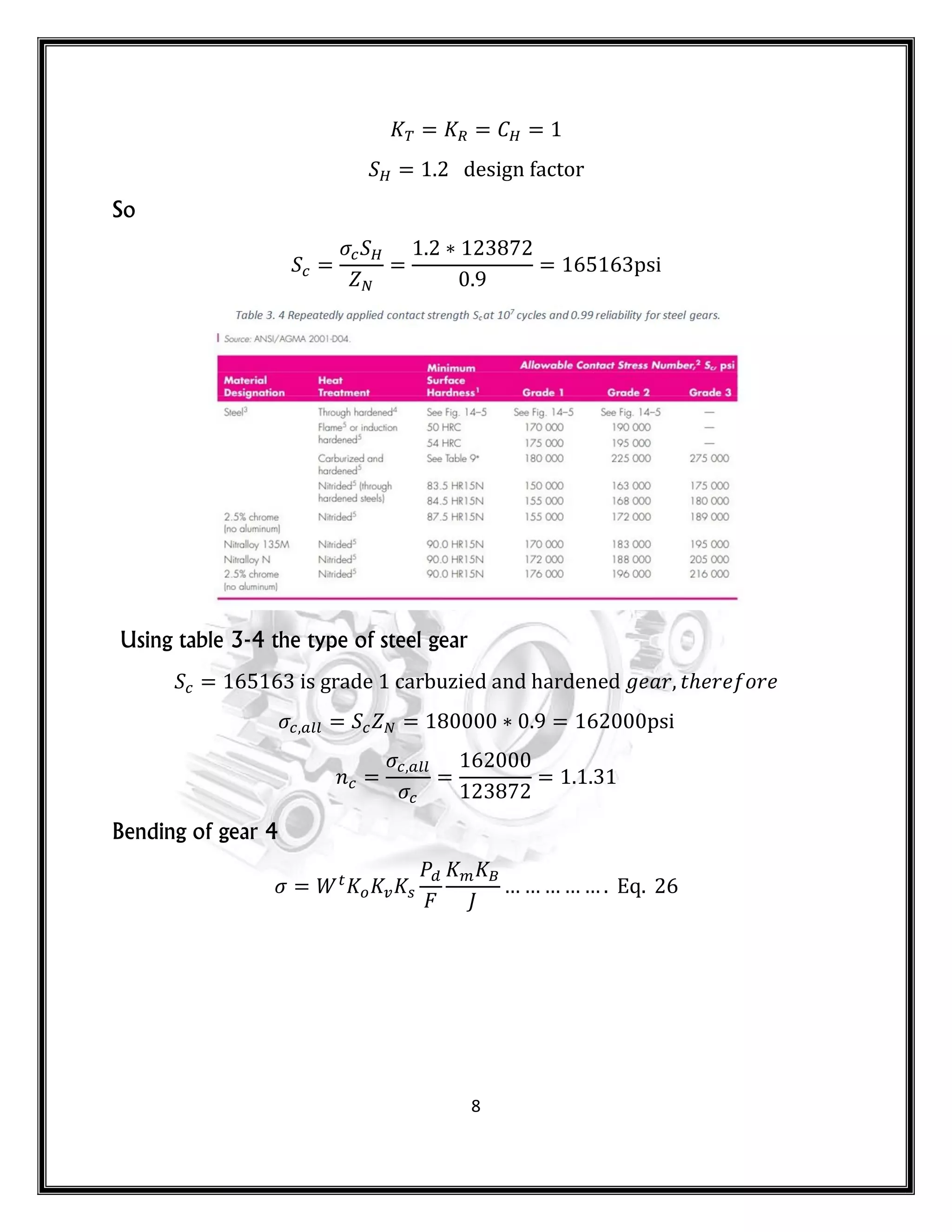
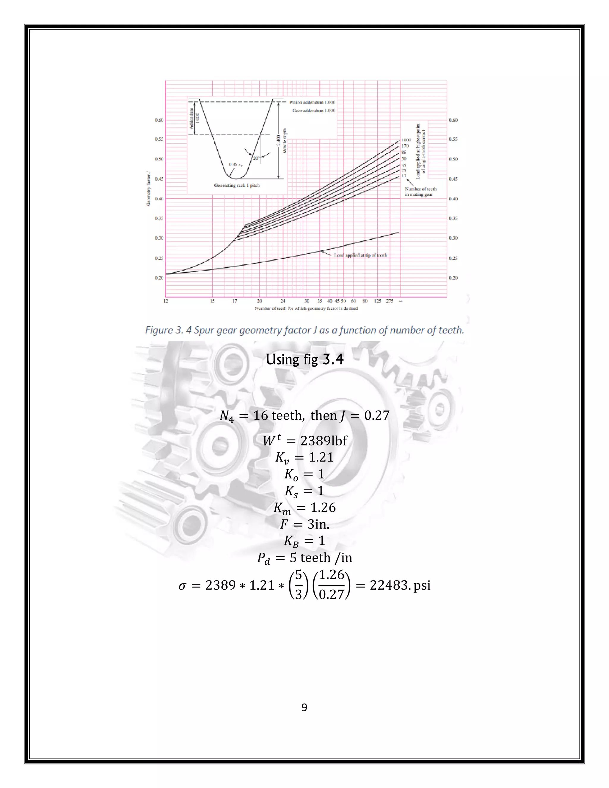
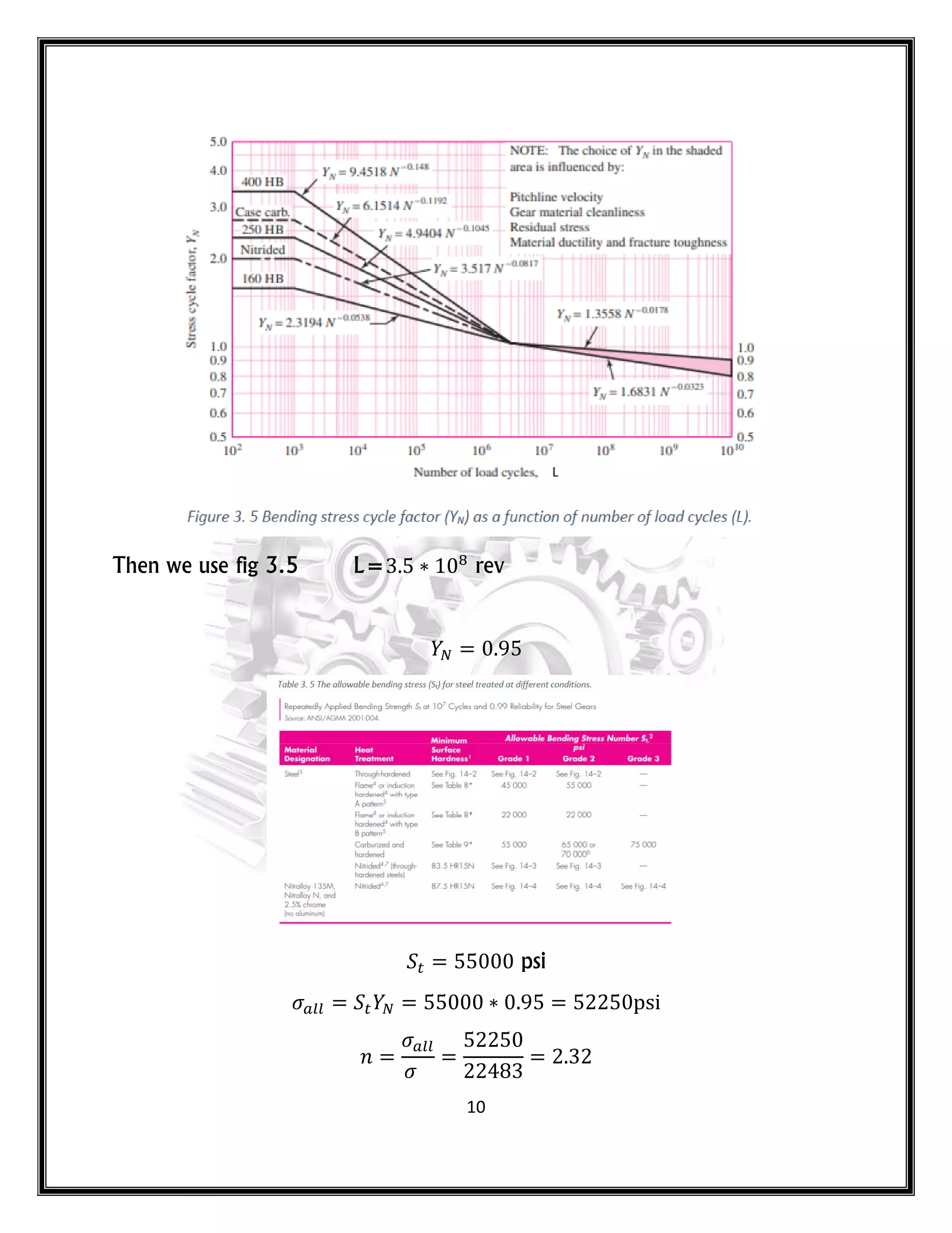
1. The document describes the design of a gear box including specifications, calculations of gear ratios and sizes, material selection, and shaft design. 2. Key specifications include delivering 27.6 hp at input speed of 1992 rpm and output speed of 103 rpm. Gears and bearings are designed to last over 13,000 hours. 3. Calculations determine the number of teeth for each gear and gear ratios. Materials including various grades of steel are selected for gears and shafts based on bending and wear stresses.


