Download as PDF, PPTX

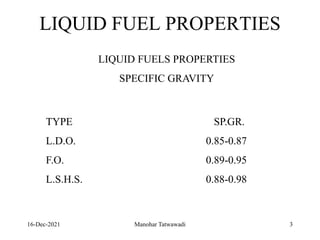
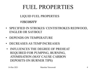
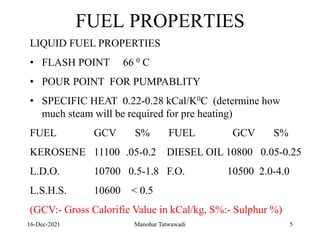
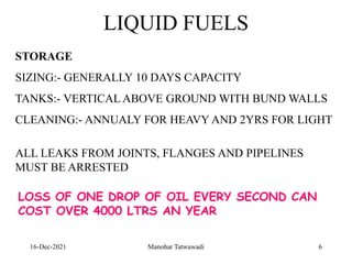
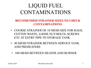
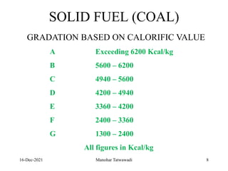
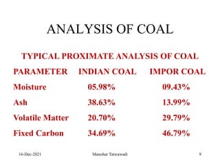
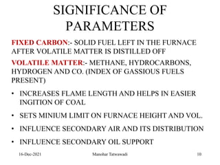
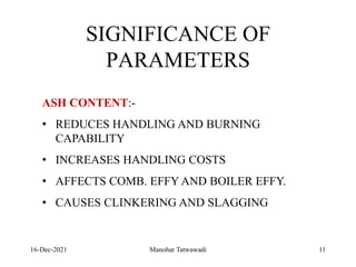
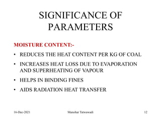
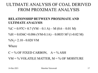
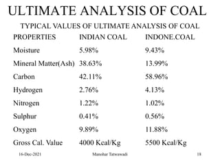
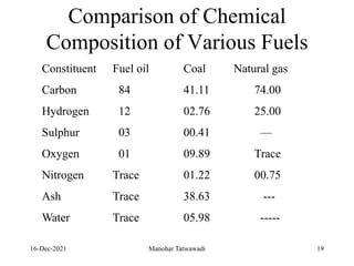
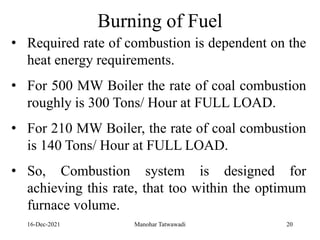

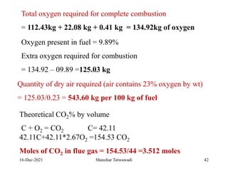
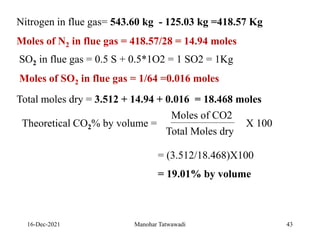
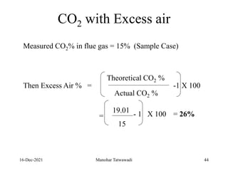
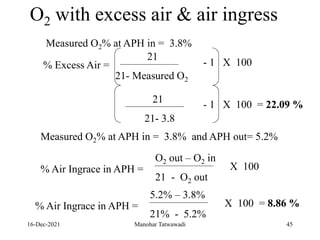

The document discusses the types and properties of fuels used in coal-based thermal power stations, focusing on liquid and solid fuels. It outlines important fuel characteristics, combustion processes, and the significance of various fuel parameters such as ash and moisture content, influencing combustion efficiency and boiler performance. Additionally, it describes combustion system design considerations and the chemical reactions involved in fuel combustion.


