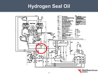
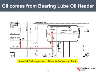
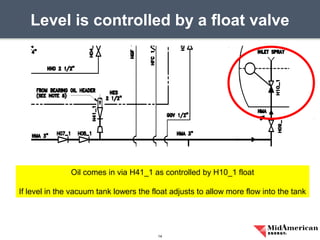
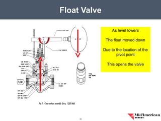
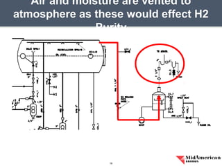
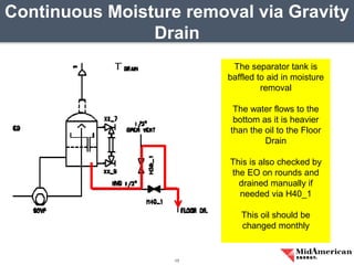
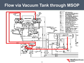
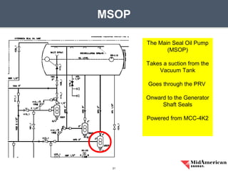
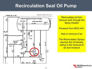
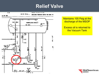
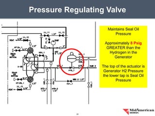
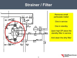
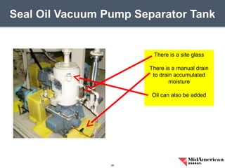
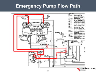
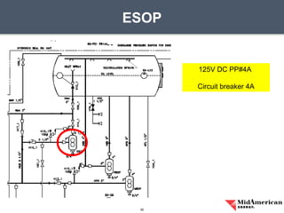
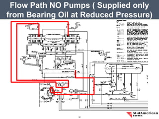
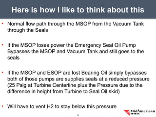
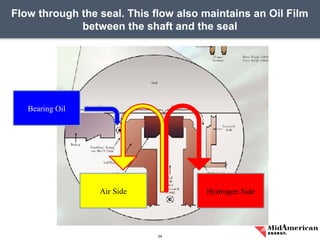
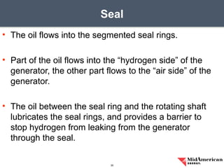
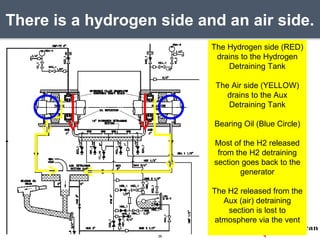
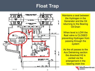
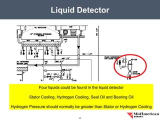
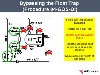
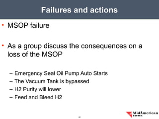
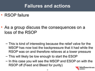
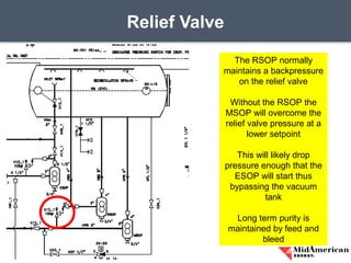
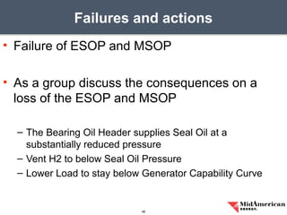
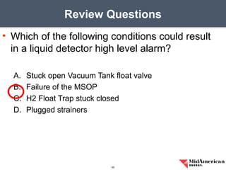
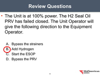
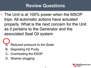
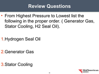
SlideShare a Scribd company logo
Unit 4 Hydrogen Seal Oil
Stephen Ford
Simulator / Training Instructor
MEC
• Please look around the room and verify there
are no hazards present
• Please place cell phones on vibrate or off
• Please keep snacking and drink areas
presentable
• Please refrain from side bar conversations so
we can all learn from questions
Training 2 Minute Drill
3
• Generator H2 Seal Oil is vital to plant operation
• Loss of H2 Seal Oil can result in an explosive
atmosphere in the plant
• Prompt operator action on component failures
can minimize equipment damage and
personnel safety
• The following is an example of damage caused
Introduction
4
Springfield Hydrogen Explosion
5
• In accordance with 04-GOS-SD STATE or
SUMMARIZE the following to an accuracy of
80% on a multiple choice examination.
– Purpose of the Generator H2 Seal Oil System
– The Flow Path of the following:
• MSOP (Main Seal Oil Pump)
• ESOP (Emergency Seal Oil Pump)
• Bearing Oil (All Pumps Off)
• Hydrogen Detraining Tank and Aux Detraining Tank
• Bearing Header
Objectives
6
• In accordance with 04-GOS-SD STATE or
SUMMARIZE the following
– Function of components
• MSOP
• SOVP (Seal Oil Vacuum Pump)
• Separator Tank
• ESOP
• RSOP
• Relief Valve
Objectives
7
• In accordance with 04-GOS-SD STATE or
SUMMARIZE the following
– Function of components
• Pressure Regulating Valve
• Strainers
• Seals
• Aux and Hydrogen Detraining tanks
• Liquid Detector
• Float Trap H-58
Objectives
8
• In accordance with 04-GOS-SD STATE or
SUMMARIZE the following
– Abnormal actions
• Vacuum Tank float fails open / closed
• Loss of MSOP
• Loss of MSOP and ESOP
• Bypassing the Float Trap
• Hi Liquid Detector Level
– Discuss the Unit 3 SER on H2 Seal Oil Cuno Failure
causing a large oil leak and how operator actions helped
Objectives
9
• Prevents H2 gas from escaping along the
Generator Shaft
• Forms a film between the Generator Shaft and
the Seal Ring
• Keeps Hydrogen in and Air out
• The Hydrogen is used to cool the generator
components
Function
10
• Why is Hydrogen used to cool the Generator
instead of air?
– Thermal Conductivity 7-10 times better than air
– Less Dense than air
– Therefore a Hydrogen Cooled Generator is smaller and
less expensive than an Air Cooled Generator
• Why not use Helium as it is an inert gas?
– Helium is so expensive the cost prevented it’s use even
Question
11
Hydrogen Seal Oil
12
Oil comes from Bearing Lube Oil Header
13
About 24 Gallons per Inch of level in the Vacuum Tank
Level is controlled by a float valve
14
Oil comes in via H41_1 as controlled by H10_1 float
If level in the vacuum tank lowers the float adjusts to allow more flow into the tank
Float Valve
15
As level lowers
The float moved down
Due to the location of the
pivot point
This opens the valve
Air and moisture are vented to
atmosphere as these would effect H2
Purity
16
Continuous Moisture removal via Gravity
Drain
17
The separator tank is
baffled to aid in moisture
removal
The water flows to the
bottom as it is heavier
than the oil to the Floor
Drain
This is also checked by
the EO on rounds and
drained manually if
needed via H40_1
This oil should be
changed monthly
Monitor via site glass and remove water
via M40_1
18
• There is moisture in the effluent going to the vent
• On a very cold day at a past power plant
• The moisture on the vent on the roof froze
• Preventing flow from the separator tank
• Evidenced by extra pressure when you drain the water from
the separator tank or pressure in the oil addition line
• Long term H2 purity could be effected
Operational Experience Lesson
19
Flow via Vacuum Tank through MSOP
20
MSOP
21
The Main Seal Oil Pump
(MSOP)
Takes a suction from the
Vacuum Tank
Goes through the PRV
Onward to the Generator
Shaft Seals
Powered from MCC-4K2
Recirculation Seal Oil Pump
22
Recirculates oil from
Vacuum tank through the
Spray Header
Powered from MCC-4A1
Aids in removal of air
The Recirculation Sprays
atomize the oil thereby
aiding in the removal of
air and moisture
Relief Valve
23
Maintains 105 Psig at the
discharge of the MSOP
Excess oil is returned to
the Vacuum Tank
• Which one of the following is a difference between a typical
relief valve and a typical safety valve?
A. The actuator closing spring on a relief valve is in a compressed state
whereas the actuator closing spring on a safety valve acts in tension.
B. A relief valve gradually opens as pressure increases above the setpoint
pressure whereas a safety valve pops open at the setpoint pressure.
C. Relief valves are capable of being gagged whereas safety valves are
not.
D. The blowdown of a relief valve is greater than the blowdown of a safety
valve.
Fundamentals Review Question
24
Pressure Regulating Valve
25
Maintains Seal Oil
Pressure
Approximately 8 Psig
GREATER than the
Hydrogen in the
Generator
The top of the actuator is
Generator H2 Pressure
the lower tap is Seal Oil
Pressure
Strainer / Filter
26
Removes small
particulate matter
One in service
One in standby
Upon high DP place the
standby filter in service
And clean the dirty filter
Seal Oil Vacuum Pump
27
Maintains approximately
0.5 PSIA in the Vacuum
Tank
The separator tank is on
top of the pump
This tank is baffled to aid
in removing oil and
moisture from the gases
discharged from the
pump
Seal Oil Vacuum Pump Separator Tank
28
There is a site glass
There is a manual drain
to drain accumulated
moisture
Oil can also be added
Emergency Pump Flow Path
29
ESOP
30
125V DC PP#4A
Circuit breaker 4A
Flow Path NO Pumps ( Supplied only
from Bearing Oil at Reduced Pressure)
32
• Normal flow path through the MSOP from the Vacuum Tank
through the Seals
• If the MSOP loses power the Emergency Seal Oil Pump
Bypasses the MSOP and Vacuum Tank and still goes to the
seals
• If the MSOP and ESOP are lost Bearing Oil simply bypasses
both of those pumps are supplies seals at a reduced pressure
(25 Psig at Turbine Centerline plus the Pressure due to the
difference in height from Turbine to Seal Oil skid)
• Will have to vent H2 to stay below this pressure
Here is how I like to think about this
33
Flow through the seal. This flow also maintains an Oil Film
between the shaft and the seal
34
Air Side Hydrogen Side
Bearing Oil
• The oil flows into the segmented seal rings.
• Part of the oil flows into the “hydrogen side” of the
generator, the other part flows to the “air side” of the
generator.
• The oil between the seal ring and the rotating shaft
lubricates the seal rings, and provides a barrier to
stop hydrogen from leaking from the generator
through the seal.
Seal
35
There is a hydrogen side and an air side.
36
The Hydrogen side (RED)
drains to the Hydrogen
Detraining Tank
The Air side (YELLOW)
drains to the Aux
Detraining Tank
Bearing Oil (Blue Circle)
Most of the H2 released
from the H2 detraining
section goes back to the
generator
The H2 released from the
Aux (air) detraining
section is lost to
atmosphere via the vent
Hydrogen Detraining Section
37
Divided into two equal
sections connected by a
loop seal
Provides circulation due
to slight differences in fan
pressures at each end of
the rotor
The larger surface area
provides for Hydrogen
bubbles to be released
It also permits oil to drain
without the oil mist being
recirculated in the
generator
Float Trap
38
Maintains a seal between
the Hydrogen in the
Generator and the Oil
returning to the Bearing
Oil Drain
When level is LOW the
float valve is CLOSED
preventing Hydrogen from
passing through the
system
As the oil passes to the
Aux Detraining section
the dissolved H2 is
vented via the
enlargement in the
bearing drain line
Aux (Air) Detraining Section
39
H2 Seal oil from the Air
side of the generator
seals is routed to the Aux
Detraining Section (Air)
This is why the Vapor
Extractor on the Turbine
Lube Oil Reservoir is so
important
Any H2 not removed via
the Drain Enlargements is
removed via the Vapor
Extractor
Liquid Detector
40
Four liquids could be found in the liquid detector
Stator Cooling, Hydrogen Cooling, Seal Oil and Bearing Oil
Hydrogen Pressure should normally be greater than Stator or Hydrogen Cooling
• Stuck Open H2 Float Trap
• As a group discuss the consequences of the
H2 Float Trap sticking open
– Generator H2 Pressure lowers quickly
– Must bypass the float trap and maintain in manual
– Check Generator Capability Curve
– Reduce Load as needed
Failures and actions
41
• As a group determine Human Performance
Tools that could be used while Bypassing the
Float Trap.
– Procedure Adherence
– Circle slash placekeeping
– STAR ( verifying the response )
– First Check from EO in the field ( Correct Unit etc.)
– Peer Check in the field if available
– Proper narrative log entry
– Proper notifications
–
Human Performance Review
42
• H2 Float Trap Stuck Closed
• As a group discuss the consequences of the
H2 Float Trap sticking closed
– Oil backs up into the detraining section
– Once it reaches the overflow it goes to the liquid detector
– Bypass the H2 Float Trap
Failures and actions
43
Bypassing the Float Trap
(Procedure 04-GOS-OI)
If the Float Trap must be
bypassed
Isolate the Float Trap
Throttle open the Bypass
H05_1
Then the site glass must
be valved in so you can
see level
Maintain level in middle of
site glass
• MSOP failure
• As a group discuss the consequences on a
loss of the MSOP
– Emergency Seal Oil Pump Auto Starts
– The Vacuum Tank is bypassed
– H2 Purity will lower
– Feed and Bleed H2
Failures and actions
45
• RSOP failure
• As a group discuss the consequences on a
loss of the RSOP
– This is kind of interesting because the relief valve for the
MSOP has now lost the backpressure that it had while the
RSOP was on and therefore relieves at a lower pressure
– This will likely be low enough to start the ESOP
– In this case you will see the MSOP and ESOP on with the
RSOP off (Feed and Bleed for purity)
Failures and actions
46
Relief Valve
47
The RSOP normally
maintains a backpressure
on the relief valve
Without the RSOP the
MSOP will overcome the
relief valve pressure at a
lower setpoint
This will likely drop
pressure enough that the
ESOP will start thus
bypassing the vacuum
tank
Long term purity is
maintained by feed and
bleed
• Failure of ESOP and MSOP
• As a group discuss the consequences on a
loss of the ESOP and MSOP
– The Bearing Oil Header supplies Seal Oil at a
substantially reduced pressure
– Vent H2 to below Seal Oil Pressure
– Lower Load to stay below Generator Capability Curve
Failures and actions
48
• Stuck Open Vacuum Tank Float Valve
• As a group discuss the consequences of the
Vacuum Tank Float Valve Sticking Open
– The Vacuum Tank Level rises
– Vacuum degrades in the Vacuum Tank
– Shut off the SOVP to prevent damage
– Shut valve H09-1 to stop flow to the Vacuum Tank
– Start the ESOP
• There was a plant that actually had oil coming out of the vent
Failures and actions
49
Lesson Learned for Stuck Open Float
Valve
50
The float valve stuck open and H09-1 was never shut
Oil eventually filled the Vacuum Tank and about 40 Gallons went through the vent
to the roof
• Stuck Closed Vacuum Tank Float Valve
• As a group discuss the consequences of the
Vacuum Tank Float Valve Sticking Closed
– MSOP trips
– ESOP starts
– Vacuum Tank is Bypassed
– Feed and Bleed to maintain purity
Failures and actions
51
• PRV fails closed
• As a group discuss the consequences of the
PRV sticking closed
– Seal oil pressure drops
– Open PRV bypass to establish 8 Psid
Failures and actions
52
• PRV fails open
• As a group discuss the consequences of the
PRV failing open
– Seal oil pressure rises
– One could throttle the PRV inlet or outlet to maintain
approximately 8 Psid
– Or fully valve out the PRV and control on the bypass
Failures and actions
53
• Strainer plugging
• As a group discuss the consequences of the
Strainer plugging
– High DP noted on strainer
– PRV will have to open more to maintain D/P
– Place online the clean strainer
– Clean the dirty strainer
Failures and actions
54
• On Friday, October 26, 2012 at approximately 1440, a
Neal 3 equipment operator was performing routine
filter cleaning of the hydrogen seal oil Cuno filter by
turning the spindle handle located on top of the filter
canister.
• While turning the handle, the spindle’s retainer came
loose and the spindle came out the top of the filter.
• Since the filter internals were pressurized with oil, a
large flow of seal oil sprayed out the top of the filter.
SER
55
• The hydrogen seal pumps were left in service while the
generator hydrogen pressure was being manually vented.
• Because of the large amount of oil spray, (See pictures at end
of report) turbine oil had to be transferred from the batch tank
to the turbine lube oil tank to maintain adequate oil flow to the
turbine bearings.
• Once the hydrogen was at an acceptable pressure, the
hydrogen seal oil system was removed from service and the
Cuno filter was valve out to stop the oil leak.
SER ( Had to Vent H2)
56
• The spill area was cleaned sufficiently to allow repairs to be
made to the Cuno filter.
• When the Cuno filter was opened, it was discovered that the
internal components had been previously removed.
• Since the hydrogen seal oil system has parallel cartridge filters
located downstream of the Cuno filter, the Cuno filter was
returned to service without internal components. Pipe plugs
were installed in place of the spindles.
SER
57
SER ( Oil Mist and Results)
58
Vented H2 to allow for securing H2 Seal
Oil System
59
• With the leak from the system H2 Seal Oil could no longer
maintain seal pressure without causing a large oil leak
• By venting H2 the pressure is reduced so it does not blow by
the seals and into the atmosphere which would create an
explosive condition
• Have shift supervisors discuss the event with their crews.
Emphasize how actions taken by the on-duty crew prevented
events from occurring, which could have been much more
severe
• The operators performed very well during this event
SER
60
• Generator H2 Seal Oil maintains the Hydrogen
in the Generator
• Any malfunction which lowers Seal Oil
Pressure below the Hydrogen Pressure must
be quickly addressed
• Normally by venting hydrogen and reducing
load
Summary
61
• The function of the Generator Seal Oil System
is to maintain (_____) in the generator and an
Oil (_____) between the Shaft and the Seal
Ring.
A. CO2, Mist
B. Nitrogen, Spray
C. Air, Blanket
D. Hydrogen, Film
Review Questions
62
• Which of the following is a correct order
components for the normal Generator Seal
flow path?
A. PRV, Seals, Strainer, MSOP
B. Seals, Strainer, PRV, MSOP
C. MSOP, PRV, Strainer, Seals
D. Strainer, PRV, MSOP, Seals
Review Questions
63
• The Unit is at 100% power when a trip of the
MSOP occurs with a failure of the ESOP to
start automatically or manually. The Unit
Operator should direct (Venting / Adding)
Hydrogen and (Raise / Reduce) Load?
A. Venting / Raise
B. Venting / Reduce
C. Adding / Raise
D. Adding / Reduce
Review Questions
64
• Which of the following conditions could result
in a liquid detector high level alarm?
A. Stuck open Vacuum Tank float valve
B. Failure of the MSOP
C. H2 Float Trap stuck closed
D. Plugged strainers
Review Questions
65
• The Unit is at 100% power. The H2 Seal Oil
PRV has failed closed. The Unit Operator will
give the following direction to the Equipment
Operator.
A. Bypass the strainers
B. Add Hydrogen
C. Start the ESOP
D. Bypass the PRV
Review Questions
66
• The Unit is at 100% power when the MSOP
trips. All automatic actions have actuated
properly. What is the next concern for the Unit
as it pertains to the Generator and the
associated Seal Oil system
A. Reduced pressure to the Seals
B. Degrading H2 Purity
C. Overheating the ESOP
D. Strainer plugging
Review Questions
67
• From Highest Pressure to Lowest list the
following in the proper order. ( Generator Gas,
Stator Cooling, H2 Seal Oil).
1.Hydrogen Seal Oil
2.Generator Gas
3.Stator Cooling
Review Questions
68
• Go back to the beginning and review the
Knowledge Objectives
• After the review ask for any questions
• Follow up with any questions not answered
during class promptly
Knowledge Objective Review
69
70
example hydrogen seal oil presentation

More Related Content

What's hot

Boiler Reheater protection
Boiler Reheater  protectionBoiler Reheater  protection
Boiler Reheater protection
anujkumarsingh79
 
Unit shutdown procedure operation
Unit shutdown procedure operationUnit shutdown procedure operation
Unit shutdown procedure operation
Nitin Patel
 
Steam Turbine and Condenser
Steam Turbine and CondenserSteam Turbine and Condenser
Steam Turbine and Condenser
Mulugeta Wotango
 
Generator cooling and sealing system 2
Generator cooling and sealing system 2Generator cooling and sealing system 2
Generator cooling and sealing system 2
Mohammad Basid
 
EH Oil System.pptx
EH Oil System.pptxEH Oil System.pptx
EH Oil System.pptx
ssuserb3fedf1
 
210 mw LMZ Turbine rolling and its GOVERNING
210 mw LMZ Turbine rolling and its GOVERNING 210 mw LMZ Turbine rolling and its GOVERNING
210 mw LMZ Turbine rolling and its GOVERNING
Nitin Patel
 
Relief and safety valves for thermal power plants
Relief and safety valves for thermal power plantsRelief and safety valves for thermal power plants
Relief and safety valves for thermal power plants
SHIVAJI CHOUDHURY
 
Power Plant Boiler feed pump
Power Plant Boiler feed pump Power Plant Boiler feed pump
Power Plant Boiler feed pump
Vundavilli Gautham
 
Hp/ lp bypass system for steam turbines
Hp/ lp bypass system for steam turbinesHp/ lp bypass system for steam turbines
Hp/ lp bypass system for steam turbines
Boben Anto Chemmannoor
 
Steam turbine introduction & maintenance ppt
Steam turbine introduction & maintenance pptSteam turbine introduction & maintenance ppt
Steam turbine introduction & maintenance ppt
Biswajit Mohanty
 
Performance calculation for feed water heater
Performance calculation  for feed water heaterPerformance calculation  for feed water heater
Performance calculation for feed water heater
SHIVAJI CHOUDHURY
 
Handling of turbine during emergencies
Handling of turbine during emergenciesHandling of turbine during emergencies
Handling of turbine during emergencies
Manohar Tatwawadi
 
Cmc philosophy
Cmc philosophyCmc philosophy
Cmc philosophy
vikash kumar upadhyay
 
Starting & Recommended Interlocks for AH,ID,FD,PA Fans & BD Valves for 270 MW...
Starting & Recommended Interlocks for AH,ID,FD,PA Fans & BD Valves for 270 MW...Starting & Recommended Interlocks for AH,ID,FD,PA Fans & BD Valves for 270 MW...
Starting & Recommended Interlocks for AH,ID,FD,PA Fans & BD Valves for 270 MW...
Manohar Tatwawadi
 
turbine governing oil system
turbine governing oil systemturbine governing oil system
turbine governing oil system
pradeep chotia
 
Electrohydraulic governing system
Electrohydraulic governing systemElectrohydraulic governing system
Electrohydraulic governing system
Ashvani Shukla
 
Steam Turbine Lube Oil System Protections Using SCADA & PLC
Steam Turbine Lube Oil System Protections Using SCADA & PLCSteam Turbine Lube Oil System Protections Using SCADA & PLC
Steam Turbine Lube Oil System Protections Using SCADA & PLC
Nilesh Jha
 
Unit lightup synchronisation & shutdown
Unit lightup synchronisation & shutdownUnit lightup synchronisation & shutdown
Unit lightup synchronisation & shutdown
Nitin Mahalle
 
Steam turbine losses
Steam turbine  lossesSteam turbine  losses
Steam turbine losses
SHIVAJI CHOUDHURY
 
Boiler Drum And Its Internals
Boiler Drum And Its InternalsBoiler Drum And Its Internals
Boiler Drum And Its Internals
Ashrant Dass
 

What's hot (20)

Boiler Reheater protection
Boiler Reheater  protectionBoiler Reheater  protection
Boiler Reheater protection
 
Unit shutdown procedure operation
Unit shutdown procedure operationUnit shutdown procedure operation
Unit shutdown procedure operation
 
Steam Turbine and Condenser
Steam Turbine and CondenserSteam Turbine and Condenser
Steam Turbine and Condenser
 
Generator cooling and sealing system 2
Generator cooling and sealing system 2Generator cooling and sealing system 2
Generator cooling and sealing system 2
 
EH Oil System.pptx
EH Oil System.pptxEH Oil System.pptx
EH Oil System.pptx
 
210 mw LMZ Turbine rolling and its GOVERNING
210 mw LMZ Turbine rolling and its GOVERNING 210 mw LMZ Turbine rolling and its GOVERNING
210 mw LMZ Turbine rolling and its GOVERNING
 
Relief and safety valves for thermal power plants
Relief and safety valves for thermal power plantsRelief and safety valves for thermal power plants
Relief and safety valves for thermal power plants
 
Power Plant Boiler feed pump
Power Plant Boiler feed pump Power Plant Boiler feed pump
Power Plant Boiler feed pump
 
Hp/ lp bypass system for steam turbines
Hp/ lp bypass system for steam turbinesHp/ lp bypass system for steam turbines
Hp/ lp bypass system for steam turbines
 
Steam turbine introduction & maintenance ppt
Steam turbine introduction & maintenance pptSteam turbine introduction & maintenance ppt
Steam turbine introduction & maintenance ppt
 
Performance calculation for feed water heater
Performance calculation  for feed water heaterPerformance calculation  for feed water heater
Performance calculation for feed water heater
 
Handling of turbine during emergencies
Handling of turbine during emergenciesHandling of turbine during emergencies
Handling of turbine during emergencies
 
Cmc philosophy
Cmc philosophyCmc philosophy
Cmc philosophy
 
Starting & Recommended Interlocks for AH,ID,FD,PA Fans & BD Valves for 270 MW...
Starting & Recommended Interlocks for AH,ID,FD,PA Fans & BD Valves for 270 MW...Starting & Recommended Interlocks for AH,ID,FD,PA Fans & BD Valves for 270 MW...
Starting & Recommended Interlocks for AH,ID,FD,PA Fans & BD Valves for 270 MW...
 
turbine governing oil system
turbine governing oil systemturbine governing oil system
turbine governing oil system
 
Electrohydraulic governing system
Electrohydraulic governing systemElectrohydraulic governing system
Electrohydraulic governing system
 
Steam Turbine Lube Oil System Protections Using SCADA & PLC
Steam Turbine Lube Oil System Protections Using SCADA & PLCSteam Turbine Lube Oil System Protections Using SCADA & PLC
Steam Turbine Lube Oil System Protections Using SCADA & PLC
 
Unit lightup synchronisation & shutdown
Unit lightup synchronisation & shutdownUnit lightup synchronisation & shutdown
Unit lightup synchronisation & shutdown
 
Steam turbine losses
Steam turbine  lossesSteam turbine  losses
Steam turbine losses
 
Boiler Drum And Its Internals
Boiler Drum And Its InternalsBoiler Drum And Its Internals
Boiler Drum And Its Internals
 

Similar to example hydrogen seal oil presentation

Hy bgc presentation for 2017 swpsc
Hy bgc presentation for 2017 swpscHy bgc presentation for 2017 swpsc
Hy bgc presentation for 2017 swpsc
EcoVapor Recovery Systems, Inc.
 
test paper - marking schedule
test paper - marking scheduletest paper - marking schedule
test paper - marking schedule
Richard Smith
 
Seal Oil System.pptx
Seal Oil System.pptxSeal Oil System.pptx
Seal Oil System.pptx
SaravananKumar264695
 
Archive for the ‘refrigerator commissioning’ tag
Archive for the ‘refrigerator commissioning’ tagArchive for the ‘refrigerator commissioning’ tag
Archive for the ‘refrigerator commissioning’ tag
Muhammad Awais
 
Hyundai hsl650 7 skid steer loader service repair manual
Hyundai hsl650 7 skid steer loader service repair manualHyundai hsl650 7 skid steer loader service repair manual
Hyundai hsl650 7 skid steer loader service repair manual
fjjsekdmme
 
Hyundai hsl650 7 skid steer loader service repair manual
Hyundai hsl650 7 skid steer loader service repair manualHyundai hsl650 7 skid steer loader service repair manual
Hyundai hsl650 7 skid steer loader service repair manual
fjjskekdmmse
 
Hydraulics-fundamentals of hydraulics.ppt
Hydraulics-fundamentals of hydraulics.pptHydraulics-fundamentals of hydraulics.ppt
Hydraulics-fundamentals of hydraulics.ppt
ArbrHalilaj
 
SEG Series.pptx
SEG Series.pptxSEG Series.pptx
SEG Series.pptx
JayeshChand2
 
Positive displacement compressors
Positive displacement compressorsPositive displacement compressors
Positive displacement compressors
Héctor Nguema Ondo
 
40266484-Fundamentals-of-Hydraulics.pdf
40266484-Fundamentals-of-Hydraulics.pdf40266484-Fundamentals-of-Hydraulics.pdf
40266484-Fundamentals-of-Hydraulics.pdf
VijaySharma983125
 
Compressors are mainly of two types: 1. Dynamic Compressors 2. Positive Disp...
Compressors are mainly of two types:  1. Dynamic Compressors 2. Positive Disp...Compressors are mainly of two types:  1. Dynamic Compressors 2. Positive Disp...
Compressors are mainly of two types: 1. Dynamic Compressors 2. Positive Disp...
mrrob05x
 
4 stroke engine
4 stroke engine4 stroke engine
4 stroke engine
bharibabu
 
Condensate Return Solutions.ppt
Condensate Return Solutions.pptCondensate Return Solutions.ppt
Condensate Return Solutions.ppt
ssuser8006c7
 
Hyundai hdf70 3 forklift truck service repair manual
Hyundai hdf70 3 forklift truck service repair manualHyundai hdf70 3 forklift truck service repair manual
Hyundai hdf70 3 forklift truck service repair manual
idkkddkmd
 
cdu and vdu unit
cdu and vdu unitcdu and vdu unit
cdu and vdu unit
KAMALESH KUMAR
 
Halderman ch097 lecture
Halderman ch097 lectureHalderman ch097 lecture
Halderman ch097 lecture
mcfalltj
 
Oil centrifuge maintenance & troubleshooting
Oil centrifuge maintenance & troubleshootingOil centrifuge maintenance & troubleshooting
Oil centrifuge maintenance & troubleshooting
waqarahmed445
 
NEO TECHNICIAN PPT.pptx
NEO TECHNICIAN PPT.pptxNEO TECHNICIAN PPT.pptx
NEO TECHNICIAN PPT.pptx
ssuserfd7531
 
Chapter 51
Chapter 51Chapter 51
Chapter 51
mcfalltj
 
Halderman ch026 lecture
Halderman ch026 lectureHalderman ch026 lecture
Halderman ch026 lecture
mcfalltj
 

Similar to example hydrogen seal oil presentation (20)

Hy bgc presentation for 2017 swpsc
Hy bgc presentation for 2017 swpscHy bgc presentation for 2017 swpsc
Hy bgc presentation for 2017 swpsc
 
test paper - marking schedule
test paper - marking scheduletest paper - marking schedule
test paper - marking schedule
 
Seal Oil System.pptx
Seal Oil System.pptxSeal Oil System.pptx
Seal Oil System.pptx
 
Archive for the ‘refrigerator commissioning’ tag
Archive for the ‘refrigerator commissioning’ tagArchive for the ‘refrigerator commissioning’ tag
Archive for the ‘refrigerator commissioning’ tag
 
Hyundai hsl650 7 skid steer loader service repair manual
Hyundai hsl650 7 skid steer loader service repair manualHyundai hsl650 7 skid steer loader service repair manual
Hyundai hsl650 7 skid steer loader service repair manual
 
Hyundai hsl650 7 skid steer loader service repair manual
Hyundai hsl650 7 skid steer loader service repair manualHyundai hsl650 7 skid steer loader service repair manual
Hyundai hsl650 7 skid steer loader service repair manual
 
Hydraulics-fundamentals of hydraulics.ppt
Hydraulics-fundamentals of hydraulics.pptHydraulics-fundamentals of hydraulics.ppt
Hydraulics-fundamentals of hydraulics.ppt
 
SEG Series.pptx
SEG Series.pptxSEG Series.pptx
SEG Series.pptx
 
Positive displacement compressors
Positive displacement compressorsPositive displacement compressors
Positive displacement compressors
 
40266484-Fundamentals-of-Hydraulics.pdf
40266484-Fundamentals-of-Hydraulics.pdf40266484-Fundamentals-of-Hydraulics.pdf
40266484-Fundamentals-of-Hydraulics.pdf
 
Compressors are mainly of two types: 1. Dynamic Compressors 2. Positive Disp...
Compressors are mainly of two types:  1. Dynamic Compressors 2. Positive Disp...Compressors are mainly of two types:  1. Dynamic Compressors 2. Positive Disp...
Compressors are mainly of two types: 1. Dynamic Compressors 2. Positive Disp...
 
4 stroke engine
4 stroke engine4 stroke engine
4 stroke engine
 
Condensate Return Solutions.ppt
Condensate Return Solutions.pptCondensate Return Solutions.ppt
Condensate Return Solutions.ppt
 
Hyundai hdf70 3 forklift truck service repair manual
Hyundai hdf70 3 forklift truck service repair manualHyundai hdf70 3 forklift truck service repair manual
Hyundai hdf70 3 forklift truck service repair manual
 
cdu and vdu unit
cdu and vdu unitcdu and vdu unit
cdu and vdu unit
 
Halderman ch097 lecture
Halderman ch097 lectureHalderman ch097 lecture
Halderman ch097 lecture
 
Oil centrifuge maintenance & troubleshooting
Oil centrifuge maintenance & troubleshootingOil centrifuge maintenance & troubleshooting
Oil centrifuge maintenance & troubleshooting
 
NEO TECHNICIAN PPT.pptx
NEO TECHNICIAN PPT.pptxNEO TECHNICIAN PPT.pptx
NEO TECHNICIAN PPT.pptx
 
Chapter 51
Chapter 51Chapter 51
Chapter 51
 
Halderman ch026 lecture
Halderman ch026 lectureHalderman ch026 lecture
Halderman ch026 lecture
 

example hydrogen seal oil presentation

  • 1. Unit 4 Hydrogen Seal Oil Stephen Ford Simulator / Training Instructor MEC
  • 2. • Please look around the room and verify there are no hazards present • Please place cell phones on vibrate or off • Please keep snacking and drink areas presentable • Please refrain from side bar conversations so we can all learn from questions Training 2 Minute Drill 3
  • 3. • Generator H2 Seal Oil is vital to plant operation • Loss of H2 Seal Oil can result in an explosive atmosphere in the plant • Prompt operator action on component failures can minimize equipment damage and personnel safety • The following is an example of damage caused Introduction 4
  • 5. • In accordance with 04-GOS-SD STATE or SUMMARIZE the following to an accuracy of 80% on a multiple choice examination. – Purpose of the Generator H2 Seal Oil System – The Flow Path of the following: • MSOP (Main Seal Oil Pump) • ESOP (Emergency Seal Oil Pump) • Bearing Oil (All Pumps Off) • Hydrogen Detraining Tank and Aux Detraining Tank • Bearing Header Objectives 6
  • 6. • In accordance with 04-GOS-SD STATE or SUMMARIZE the following – Function of components • MSOP • SOVP (Seal Oil Vacuum Pump) • Separator Tank • ESOP • RSOP • Relief Valve Objectives 7
  • 7. • In accordance with 04-GOS-SD STATE or SUMMARIZE the following – Function of components • Pressure Regulating Valve • Strainers • Seals • Aux and Hydrogen Detraining tanks • Liquid Detector • Float Trap H-58 Objectives 8
  • 8. • In accordance with 04-GOS-SD STATE or SUMMARIZE the following – Abnormal actions • Vacuum Tank float fails open / closed • Loss of MSOP • Loss of MSOP and ESOP • Bypassing the Float Trap • Hi Liquid Detector Level – Discuss the Unit 3 SER on H2 Seal Oil Cuno Failure causing a large oil leak and how operator actions helped Objectives 9
  • 9. • Prevents H2 gas from escaping along the Generator Shaft • Forms a film between the Generator Shaft and the Seal Ring • Keeps Hydrogen in and Air out • The Hydrogen is used to cool the generator components Function 10
  • 10. • Why is Hydrogen used to cool the Generator instead of air? – Thermal Conductivity 7-10 times better than air – Less Dense than air – Therefore a Hydrogen Cooled Generator is smaller and less expensive than an Air Cooled Generator • Why not use Helium as it is an inert gas? – Helium is so expensive the cost prevented it’s use even Question 11
  • 12. Oil comes from Bearing Lube Oil Header 13 About 24 Gallons per Inch of level in the Vacuum Tank
  • 13. Level is controlled by a float valve 14 Oil comes in via H41_1 as controlled by H10_1 float If level in the vacuum tank lowers the float adjusts to allow more flow into the tank
  • 14. Float Valve 15 As level lowers The float moved down Due to the location of the pivot point This opens the valve
  • 15. Air and moisture are vented to atmosphere as these would effect H2 Purity 16
  • 16. Continuous Moisture removal via Gravity Drain 17 The separator tank is baffled to aid in moisture removal The water flows to the bottom as it is heavier than the oil to the Floor Drain This is also checked by the EO on rounds and drained manually if needed via H40_1 This oil should be changed monthly
  • 17. Monitor via site glass and remove water via M40_1 18
  • 18. • There is moisture in the effluent going to the vent • On a very cold day at a past power plant • The moisture on the vent on the roof froze • Preventing flow from the separator tank • Evidenced by extra pressure when you drain the water from the separator tank or pressure in the oil addition line • Long term H2 purity could be effected Operational Experience Lesson 19
  • 19. Flow via Vacuum Tank through MSOP 20
  • 20. MSOP 21 The Main Seal Oil Pump (MSOP) Takes a suction from the Vacuum Tank Goes through the PRV Onward to the Generator Shaft Seals Powered from MCC-4K2
  • 21. Recirculation Seal Oil Pump 22 Recirculates oil from Vacuum tank through the Spray Header Powered from MCC-4A1 Aids in removal of air The Recirculation Sprays atomize the oil thereby aiding in the removal of air and moisture
  • 22. Relief Valve 23 Maintains 105 Psig at the discharge of the MSOP Excess oil is returned to the Vacuum Tank
  • 23. • Which one of the following is a difference between a typical relief valve and a typical safety valve? A. The actuator closing spring on a relief valve is in a compressed state whereas the actuator closing spring on a safety valve acts in tension. B. A relief valve gradually opens as pressure increases above the setpoint pressure whereas a safety valve pops open at the setpoint pressure. C. Relief valves are capable of being gagged whereas safety valves are not. D. The blowdown of a relief valve is greater than the blowdown of a safety valve. Fundamentals Review Question 24
  • 24. Pressure Regulating Valve 25 Maintains Seal Oil Pressure Approximately 8 Psig GREATER than the Hydrogen in the Generator The top of the actuator is Generator H2 Pressure the lower tap is Seal Oil Pressure
  • 25. Strainer / Filter 26 Removes small particulate matter One in service One in standby Upon high DP place the standby filter in service And clean the dirty filter
  • 26. Seal Oil Vacuum Pump 27 Maintains approximately 0.5 PSIA in the Vacuum Tank The separator tank is on top of the pump This tank is baffled to aid in removing oil and moisture from the gases discharged from the pump
  • 27. Seal Oil Vacuum Pump Separator Tank 28 There is a site glass There is a manual drain to drain accumulated moisture Oil can also be added
  • 30. Flow Path NO Pumps ( Supplied only from Bearing Oil at Reduced Pressure) 32
  • 31. • Normal flow path through the MSOP from the Vacuum Tank through the Seals • If the MSOP loses power the Emergency Seal Oil Pump Bypasses the MSOP and Vacuum Tank and still goes to the seals • If the MSOP and ESOP are lost Bearing Oil simply bypasses both of those pumps are supplies seals at a reduced pressure (25 Psig at Turbine Centerline plus the Pressure due to the difference in height from Turbine to Seal Oil skid) • Will have to vent H2 to stay below this pressure Here is how I like to think about this 33
  • 32. Flow through the seal. This flow also maintains an Oil Film between the shaft and the seal 34 Air Side Hydrogen Side Bearing Oil
  • 33. • The oil flows into the segmented seal rings. • Part of the oil flows into the “hydrogen side” of the generator, the other part flows to the “air side” of the generator. • The oil between the seal ring and the rotating shaft lubricates the seal rings, and provides a barrier to stop hydrogen from leaking from the generator through the seal. Seal 35
  • 34. There is a hydrogen side and an air side. 36 The Hydrogen side (RED) drains to the Hydrogen Detraining Tank The Air side (YELLOW) drains to the Aux Detraining Tank Bearing Oil (Blue Circle) Most of the H2 released from the H2 detraining section goes back to the generator The H2 released from the Aux (air) detraining section is lost to atmosphere via the vent
  • 35. Hydrogen Detraining Section 37 Divided into two equal sections connected by a loop seal Provides circulation due to slight differences in fan pressures at each end of the rotor The larger surface area provides for Hydrogen bubbles to be released It also permits oil to drain without the oil mist being recirculated in the generator
  • 36. Float Trap 38 Maintains a seal between the Hydrogen in the Generator and the Oil returning to the Bearing Oil Drain When level is LOW the float valve is CLOSED preventing Hydrogen from passing through the system As the oil passes to the Aux Detraining section the dissolved H2 is vented via the enlargement in the bearing drain line
  • 37. Aux (Air) Detraining Section 39 H2 Seal oil from the Air side of the generator seals is routed to the Aux Detraining Section (Air) This is why the Vapor Extractor on the Turbine Lube Oil Reservoir is so important Any H2 not removed via the Drain Enlargements is removed via the Vapor Extractor
  • 38. Liquid Detector 40 Four liquids could be found in the liquid detector Stator Cooling, Hydrogen Cooling, Seal Oil and Bearing Oil Hydrogen Pressure should normally be greater than Stator or Hydrogen Cooling
  • 39. • Stuck Open H2 Float Trap • As a group discuss the consequences of the H2 Float Trap sticking open – Generator H2 Pressure lowers quickly – Must bypass the float trap and maintain in manual – Check Generator Capability Curve – Reduce Load as needed Failures and actions 41
  • 40. • As a group determine Human Performance Tools that could be used while Bypassing the Float Trap. – Procedure Adherence – Circle slash placekeeping – STAR ( verifying the response ) – First Check from EO in the field ( Correct Unit etc.) – Peer Check in the field if available – Proper narrative log entry – Proper notifications – Human Performance Review 42
  • 41. • H2 Float Trap Stuck Closed • As a group discuss the consequences of the H2 Float Trap sticking closed – Oil backs up into the detraining section – Once it reaches the overflow it goes to the liquid detector – Bypass the H2 Float Trap Failures and actions 43
  • 42. Bypassing the Float Trap (Procedure 04-GOS-OI) If the Float Trap must be bypassed Isolate the Float Trap Throttle open the Bypass H05_1 Then the site glass must be valved in so you can see level Maintain level in middle of site glass
  • 43. • MSOP failure • As a group discuss the consequences on a loss of the MSOP – Emergency Seal Oil Pump Auto Starts – The Vacuum Tank is bypassed – H2 Purity will lower – Feed and Bleed H2 Failures and actions 45
  • 44. • RSOP failure • As a group discuss the consequences on a loss of the RSOP – This is kind of interesting because the relief valve for the MSOP has now lost the backpressure that it had while the RSOP was on and therefore relieves at a lower pressure – This will likely be low enough to start the ESOP – In this case you will see the MSOP and ESOP on with the RSOP off (Feed and Bleed for purity) Failures and actions 46
  • 45. Relief Valve 47 The RSOP normally maintains a backpressure on the relief valve Without the RSOP the MSOP will overcome the relief valve pressure at a lower setpoint This will likely drop pressure enough that the ESOP will start thus bypassing the vacuum tank Long term purity is maintained by feed and bleed
  • 46. • Failure of ESOP and MSOP • As a group discuss the consequences on a loss of the ESOP and MSOP – The Bearing Oil Header supplies Seal Oil at a substantially reduced pressure – Vent H2 to below Seal Oil Pressure – Lower Load to stay below Generator Capability Curve Failures and actions 48
  • 47. • Stuck Open Vacuum Tank Float Valve • As a group discuss the consequences of the Vacuum Tank Float Valve Sticking Open – The Vacuum Tank Level rises – Vacuum degrades in the Vacuum Tank – Shut off the SOVP to prevent damage – Shut valve H09-1 to stop flow to the Vacuum Tank – Start the ESOP • There was a plant that actually had oil coming out of the vent Failures and actions 49
  • 48. Lesson Learned for Stuck Open Float Valve 50 The float valve stuck open and H09-1 was never shut Oil eventually filled the Vacuum Tank and about 40 Gallons went through the vent to the roof
  • 49. • Stuck Closed Vacuum Tank Float Valve • As a group discuss the consequences of the Vacuum Tank Float Valve Sticking Closed – MSOP trips – ESOP starts – Vacuum Tank is Bypassed – Feed and Bleed to maintain purity Failures and actions 51
  • 50. • PRV fails closed • As a group discuss the consequences of the PRV sticking closed – Seal oil pressure drops – Open PRV bypass to establish 8 Psid Failures and actions 52
  • 51. • PRV fails open • As a group discuss the consequences of the PRV failing open – Seal oil pressure rises – One could throttle the PRV inlet or outlet to maintain approximately 8 Psid – Or fully valve out the PRV and control on the bypass Failures and actions 53
  • 52. • Strainer plugging • As a group discuss the consequences of the Strainer plugging – High DP noted on strainer – PRV will have to open more to maintain D/P – Place online the clean strainer – Clean the dirty strainer Failures and actions 54
  • 53. • On Friday, October 26, 2012 at approximately 1440, a Neal 3 equipment operator was performing routine filter cleaning of the hydrogen seal oil Cuno filter by turning the spindle handle located on top of the filter canister. • While turning the handle, the spindle’s retainer came loose and the spindle came out the top of the filter. • Since the filter internals were pressurized with oil, a large flow of seal oil sprayed out the top of the filter. SER 55
  • 54. • The hydrogen seal pumps were left in service while the generator hydrogen pressure was being manually vented. • Because of the large amount of oil spray, (See pictures at end of report) turbine oil had to be transferred from the batch tank to the turbine lube oil tank to maintain adequate oil flow to the turbine bearings. • Once the hydrogen was at an acceptable pressure, the hydrogen seal oil system was removed from service and the Cuno filter was valve out to stop the oil leak. SER ( Had to Vent H2) 56
  • 55. • The spill area was cleaned sufficiently to allow repairs to be made to the Cuno filter. • When the Cuno filter was opened, it was discovered that the internal components had been previously removed. • Since the hydrogen seal oil system has parallel cartridge filters located downstream of the Cuno filter, the Cuno filter was returned to service without internal components. Pipe plugs were installed in place of the spindles. SER 57
  • 56. SER ( Oil Mist and Results) 58
  • 57. Vented H2 to allow for securing H2 Seal Oil System 59
  • 58. • With the leak from the system H2 Seal Oil could no longer maintain seal pressure without causing a large oil leak • By venting H2 the pressure is reduced so it does not blow by the seals and into the atmosphere which would create an explosive condition • Have shift supervisors discuss the event with their crews. Emphasize how actions taken by the on-duty crew prevented events from occurring, which could have been much more severe • The operators performed very well during this event SER 60
  • 59. • Generator H2 Seal Oil maintains the Hydrogen in the Generator • Any malfunction which lowers Seal Oil Pressure below the Hydrogen Pressure must be quickly addressed • Normally by venting hydrogen and reducing load Summary 61
  • 60. • The function of the Generator Seal Oil System is to maintain (_____) in the generator and an Oil (_____) between the Shaft and the Seal Ring. A. CO2, Mist B. Nitrogen, Spray C. Air, Blanket D. Hydrogen, Film Review Questions 62
  • 61. • Which of the following is a correct order components for the normal Generator Seal flow path? A. PRV, Seals, Strainer, MSOP B. Seals, Strainer, PRV, MSOP C. MSOP, PRV, Strainer, Seals D. Strainer, PRV, MSOP, Seals Review Questions 63
  • 62. • The Unit is at 100% power when a trip of the MSOP occurs with a failure of the ESOP to start automatically or manually. The Unit Operator should direct (Venting / Adding) Hydrogen and (Raise / Reduce) Load? A. Venting / Raise B. Venting / Reduce C. Adding / Raise D. Adding / Reduce Review Questions 64
  • 63. • Which of the following conditions could result in a liquid detector high level alarm? A. Stuck open Vacuum Tank float valve B. Failure of the MSOP C. H2 Float Trap stuck closed D. Plugged strainers Review Questions 65
  • 64. • The Unit is at 100% power. The H2 Seal Oil PRV has failed closed. The Unit Operator will give the following direction to the Equipment Operator. A. Bypass the strainers B. Add Hydrogen C. Start the ESOP D. Bypass the PRV Review Questions 66
  • 65. • The Unit is at 100% power when the MSOP trips. All automatic actions have actuated properly. What is the next concern for the Unit as it pertains to the Generator and the associated Seal Oil system A. Reduced pressure to the Seals B. Degrading H2 Purity C. Overheating the ESOP D. Strainer plugging Review Questions 67
  • 66. • From Highest Pressure to Lowest list the following in the proper order. ( Generator Gas, Stator Cooling, H2 Seal Oil). 1.Hydrogen Seal Oil 2.Generator Gas 3.Stator Cooling Review Questions 68
  • 67. • Go back to the beginning and review the Knowledge Objectives • After the review ask for any questions • Follow up with any questions not answered during class promptly Knowledge Objective Review 69
  • 68. 70

Editor's Notes

  1. H2 is used because it is lighter than air resulting in less windage losses and has a better thermal conductivity than air.
  2. H2 is used because it is lighter than air resulting in less windage losses and has a better thermal conductivity than air.
  3. Answer A is wrong because the spring for closing is compressed not tensioned upon opening of the safety. C is wrong because both can be ganged. D is wrong because blowdown can be set by adjusting the parameters of the valve