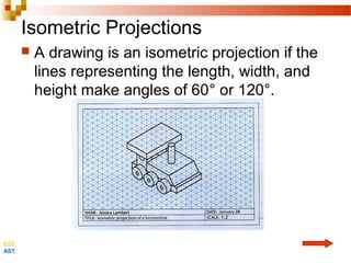
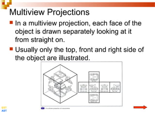
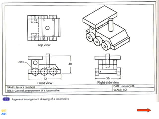
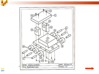
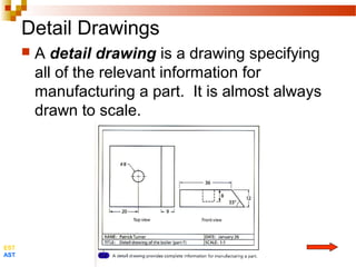
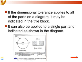
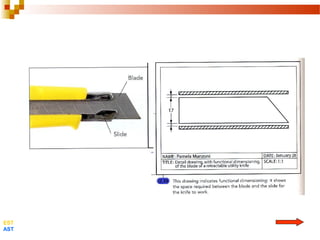
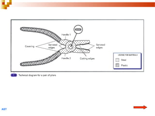
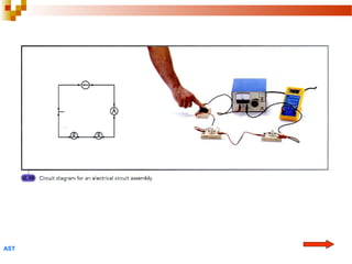
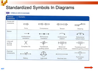
The Technological
World
3. Technical Drafting
 Before a technical object can be
manufactured, its shape and dimensions
must be determined. A technical drawing
must be created.
 Technical drawings can be made by hand
or on a computer.
 To understand these drawings, we must
be able to recognize and analyze different
projections.
EST
AST
3.1 Projections
 A projection is the representation of a
three-dimensional object on a two-
dimensional surface.
 Two of the most commonly used
projections are:
1. isometric
2. multiview.
EST
AST
Isometric Projections
 A drawing is an isometric projection if the
lines representing the length, width, and
height make angles of 60° or 120°.
EST
AST
Multiview Projections
 In a multiview projection, each face of the
object is drawn separately looking at it
from straight on.
 Usually only the top, front and right side of
the object are illustrated.
EST
AST
 Isometric projections show the object in
perspective. It represents the three
dimensions of the object in a single
drawing.
 Multiview projections usually provide
greater detail without distortion.
EST
AST
3.2 Engineering Drawings
 A general arrangement is a technical
drawing representing the overall
appearance on an object.
 It usually includes the top, front, and right
side multiviews as well as an isometric
projection drawn to scale.
 The general arrangement will also include
a title block showing important
information about the object
EST
AST
EST
AST
Exploded Views
 An exploded view is a drawing in which
the various parts of the object are
separated from one another so as to more
easily visualize the componet parts of the
object.
 The drawing will use an isometric
projection drawn to scale.
 The is accompanied by a list of parts
indicating their names and the number of
each part required.
EST
AST
EST
AST
Detail Drawings
 A detail drawing is a drawing specifying
all of the relevant information for
manufacturing a part. It is almost always
drawn to scale.
EST
AST
Dimensional Tolerances
 Since machines, tools, instruments, and
the operators of machines are not perfect,
the manufactured parts may be slightly
different from the dimensions indicated on
the drawing.
 A dimensional tolerance is an indicator
of the maximum acceptable difference
between a specified measurement and the
actual measurement on the finished
object.
EST
AST
 If the dimensional tolerance applies to all
of the parts on a diagram, it may be
indicated in the title block.
 It can also be applied to a single part and
indicated as shown in the diagram.
EST
AST
Functional Dimensioning
 The functional dimensioning of a
drawing specifies the information required
for the object to work.
 For example, the play required for a blade
to slide freely in a utility knife is shown as
the space between the blade and the
guide.
EST
AST
EST
AST
Developments
 A development is the representation of
the surface area required to make a part
by bending.
 Sheet metal is often used to manufacture
a technical object. The development
shows the surface area of the material as
well as the lines where the sheet will be
bent.
EST
AST
EST
AST
3.3 Diagrammatic Representations
 A diagram is a simplified representation of an
object, a part of an object, or a system.
 Diagrams are used to help explain an object’s
operating principals as well as any other
characteristics that must considered during the
manufacturing process.
 Depending on the type of information that a
drafter wishes to display, one of the following
common diagrams will be chosen:
 Design Plan
 Technical Diagram
 Circuit Diagram
AST
The Most Common Types of Diagrams
AST
AST
AST
AST
Standardized Symbols In Diagrams
AST
Checkup
 Observatory: The Environment
Page 419, Questions 1 to 10
EST
AST
4. Manufacturing: Tools and
Techniques
 Once the materials have been choosen and the
plans have been drawn, the object must be
manufactured.
 Manufacturing is a series of operations
resulting in the creation of a technical object.
 The various steps in the manufacturing of an
object require the use of various instuments.
EST
AST
 A tool is and instrument used in the
manufacture of an object.
 A hand tool is powered by human force.
 A machine tool is powered by forces
other than human.
 The manufacturing process is usually
divided into three parts:
1. Measuring and laying out the parts
2. Machining the parts
3. Assembling and finishing the parts
EST
AST
4.1 Measuring and Laying Out
 The information needed for the
manufacturing of an object can be found
in the detailed drawings of the object, or
on its manufacturing process sheet.
 The manufacturing process sheet is a
document describing a series of operation
to perform in the manufacturing of a given
part and listing the materials and tools
required.
EST
AST
 Measuring out is the act of determining
the size or position of a marking.
 Laying out is the act of tracing markings
or reference points onto a material.
EST
AST
4.2 Machining
 Machining consists of shaping a material
into a desired configuration.
 The first step in machining a part is to cut
it out roughly into its approximate shape.
 The most commons techniques used in
this step are cutting, drilling, tapping,
threading, and bending.
EST
AST
 Cutting consists of giving a material a desired
shape.
 Drilling consist of making a hole in a material.
 Tapping is a machining technique in which
screw threads are formed inside holes drilled
into a material.
 Threading is a machining technique in which
screw threads are formed around a rod.
 Bending is a machining technique in which a
material is curved into a certain shape.
EST
AST
Inspection
 Throughout the machining phase, the
parts are measured and inspected to
ensure that they match the required
specifications.
AST
4.3 Assembling and Finishing
 Assembling is a set of techniques by which
various parts are united to form a complete
technical object. Techniques used for
assembling include: nailing, screwing, bonding,
riveting, bolting, and welding.
 Finishing is a set of techniques that complete
the manufacture of the parts of a technical
object. The finish protects the materials from
the elements and enhances the appearance of
the object. Finishing techniques include:
painting, vanishing, staining, and polishing.
EST
AST
Checkup
 Observatory: The Environment
Page 420, Questions 11 to 14
Review
 Observatory: The Environment
Page 421, Review Questions A to D
Credits
 All images are from:
Observatory: The Environment
Editions du Renouveau Pedagogique Inc

Technical drawing & assembly

  • 1.
  • 2.
    3. Technical Drafting Before a technical object can be manufactured, its shape and dimensions must be determined. A technical drawing must be created.  Technical drawings can be made by hand or on a computer.  To understand these drawings, we must be able to recognize and analyze different projections. EST AST
  • 3.
    3.1 Projections  Aprojection is the representation of a three-dimensional object on a two- dimensional surface.  Two of the most commonly used projections are: 1. isometric 2. multiview. EST AST
  • 4.
    Isometric Projections  Adrawing is an isometric projection if the lines representing the length, width, and height make angles of 60° or 120°. EST AST
  • 5.
    Multiview Projections  Ina multiview projection, each face of the object is drawn separately looking at it from straight on.  Usually only the top, front and right side of the object are illustrated. EST AST
  • 6.
     Isometric projectionsshow the object in perspective. It represents the three dimensions of the object in a single drawing.  Multiview projections usually provide greater detail without distortion. EST AST
  • 7.
    3.2 Engineering Drawings A general arrangement is a technical drawing representing the overall appearance on an object.  It usually includes the top, front, and right side multiviews as well as an isometric projection drawn to scale.  The general arrangement will also include a title block showing important information about the object EST AST
  • 8.
  • 9.
    Exploded Views  Anexploded view is a drawing in which the various parts of the object are separated from one another so as to more easily visualize the componet parts of the object.  The drawing will use an isometric projection drawn to scale.  The is accompanied by a list of parts indicating their names and the number of each part required. EST AST
  • 10.
  • 11.
    Detail Drawings  Adetail drawing is a drawing specifying all of the relevant information for manufacturing a part. It is almost always drawn to scale. EST AST
  • 12.
    Dimensional Tolerances  Sincemachines, tools, instruments, and the operators of machines are not perfect, the manufactured parts may be slightly different from the dimensions indicated on the drawing.  A dimensional tolerance is an indicator of the maximum acceptable difference between a specified measurement and the actual measurement on the finished object. EST AST
  • 13.
     If thedimensional tolerance applies to all of the parts on a diagram, it may be indicated in the title block.  It can also be applied to a single part and indicated as shown in the diagram. EST AST
  • 14.
    Functional Dimensioning  Thefunctional dimensioning of a drawing specifies the information required for the object to work.  For example, the play required for a blade to slide freely in a utility knife is shown as the space between the blade and the guide. EST AST
  • 15.
  • 16.
    Developments  A developmentis the representation of the surface area required to make a part by bending.  Sheet metal is often used to manufacture a technical object. The development shows the surface area of the material as well as the lines where the sheet will be bent. EST AST
  • 17.
  • 18.
    3.3 Diagrammatic Representations A diagram is a simplified representation of an object, a part of an object, or a system.  Diagrams are used to help explain an object’s operating principals as well as any other characteristics that must considered during the manufacturing process.  Depending on the type of information that a drafter wishes to display, one of the following common diagrams will be chosen:  Design Plan  Technical Diagram  Circuit Diagram AST
  • 19.
    The Most CommonTypes of Diagrams AST
  • 20.
  • 21.
  • 22.
  • 23.
  • 24.
    Checkup  Observatory: TheEnvironment Page 419, Questions 1 to 10 EST AST
  • 25.
    4. Manufacturing: Toolsand Techniques  Once the materials have been choosen and the plans have been drawn, the object must be manufactured.  Manufacturing is a series of operations resulting in the creation of a technical object.  The various steps in the manufacturing of an object require the use of various instuments. EST AST
  • 26.
     A toolis and instrument used in the manufacture of an object.  A hand tool is powered by human force.  A machine tool is powered by forces other than human.  The manufacturing process is usually divided into three parts: 1. Measuring and laying out the parts 2. Machining the parts 3. Assembling and finishing the parts EST AST
  • 27.
    4.1 Measuring andLaying Out  The information needed for the manufacturing of an object can be found in the detailed drawings of the object, or on its manufacturing process sheet.  The manufacturing process sheet is a document describing a series of operation to perform in the manufacturing of a given part and listing the materials and tools required. EST AST
  • 28.
     Measuring outis the act of determining the size or position of a marking.  Laying out is the act of tracing markings or reference points onto a material. EST AST
  • 29.
    4.2 Machining  Machiningconsists of shaping a material into a desired configuration.  The first step in machining a part is to cut it out roughly into its approximate shape.  The most commons techniques used in this step are cutting, drilling, tapping, threading, and bending. EST AST
  • 30.
     Cutting consistsof giving a material a desired shape.  Drilling consist of making a hole in a material.  Tapping is a machining technique in which screw threads are formed inside holes drilled into a material.  Threading is a machining technique in which screw threads are formed around a rod.  Bending is a machining technique in which a material is curved into a certain shape. EST AST
  • 31.
    Inspection  Throughout themachining phase, the parts are measured and inspected to ensure that they match the required specifications. AST
  • 32.
    4.3 Assembling andFinishing  Assembling is a set of techniques by which various parts are united to form a complete technical object. Techniques used for assembling include: nailing, screwing, bonding, riveting, bolting, and welding.  Finishing is a set of techniques that complete the manufacture of the parts of a technical object. The finish protects the materials from the elements and enhances the appearance of the object. Finishing techniques include: painting, vanishing, staining, and polishing. EST AST
  • 33.
    Checkup  Observatory: TheEnvironment Page 420, Questions 11 to 14
  • 34.
    Review  Observatory: TheEnvironment Page 421, Review Questions A to D Credits  All images are from: Observatory: The Environment Editions du Renouveau Pedagogique Inc