This document provides an introduction to preparing drawings using Computer-Aided Design (CAD) for a Grade 10 ICT - Technical Drafting course. It begins with an overview of the module's objectives and time allotment. Next, it defines key technical terms related to operating CAD software and computer hardware. The main body describes the basic components of a computer system, including the central processing unit, keyboard, monitor, hard disk drive, optical drive, mouse, and digitizer tablet. It provides examples of each component and explains their basic functions.
ICT- TECHNICAL DRAFTING- Grade 10
35
Content Standard Performance Standard
The learner demonstrates
understanding of concepts and
underlying principles in the
preparation of drawings using
Computer-Aided Design (CAD).
The learner independently prepare
drawings using Computer-Aided
Design (CAD) based on established
industry and/or job requirements.
Quarter I and II Time Allotment: 80 hrs.
MODULE 3
PREPARING DRAWING USING COMPUTER-AIDED DESIGN
(CAD)
Introduction
Technology and Livelihood Education (TLE) of the K to 12 Basic
Education Program (BEP) is composed of four components namely: Agri-
Fishery Arts, Home Economics, Industrial Arts and Information and
Communication Technology (ICT). In this module, the focus is on ICT –
Preparing Drawings using Computer-Aided Design (CAD).
This course introduces the different learning activities that will prepare
you to be a skillful draftsman before you take the plunge into the business of
CAD. The skills learned will make you feel more confident while providing
support where it is needed.
This module is specifically designed to hone your skills and knowledge
on Process and Delivery of CAD enriched with hands-on activities. Learning
procedures are divided into different sections such as: What to Know, What
to Process, What to Reflect and Understand and What to Transfer
So, explore and experience the lessons in Preparing a Computer-
Aided Drawing and be a step closer to being a draftsman.
2.
ICT- TECHNICAL DRAFTING- Grade 10
36
ENJOY YOUR JOURNEY!
Objectives:
Upon completion of this module, you are expected to:
operate CAD software and computer hardware; and
prepare plan using CAD
*****
Pre- Assessment:
You will be challenged to recall your prior knowledge and previous
experiences about Technical Drafting. This phase will guide you in assessing
yourself by answering the questions below before you further explore the
basics of preparing computer-aided drawings.
Directions: Choose the letter of the correct answer. Write your answer in the
space provided for before each number.
_____ 1. This is commonly known as the physical equipment that makes up
the computer system.
A. Hardware B. Mouse C. Printer D. Software
_____ 2. It is the brain of the computer where most of the “computing” takes
place.
A. CPU B. Disk Drive C. Hardware D. Monitor
3.
ICT- TECHNICAL DRAFTING- Grade 10
37
_____ 3. This is the main purpose of the left mouse button.
A. To execute a command C. To serve as abort button
B. To repeat the last command D. To serve as pick button
_____ 4. The set of programs, and other related applications associated with
a computer system.
A. Disk Drive C. Printer
B. Hardware D. Software
_____ 5. Of the following softwares, which is not an application software?
A. Adobe Photoshop C. Flash
B. AutoCAD D. Windows 8
_____ 6. Which of the following options is not a type of workspaces?
A. 2D Drafting & Annotation C. 3D Modeling
B. My workspace D. AutoCAD Classic
_____ 7. Which of the function keys can be used for activating the Osnap
Mode?
A. F3 B. F5 C. F9 D. F8
_____ 8. Which command is used to change the size of an existing objects?
A. Move B. Rotate C. Scale D. Zoom
_____ 9. Which command can be used to create a new text style (TS) and
modify the existing ones?
A. Dtext B. Mtext C. Text D. Style
_____ 10. Which of the keyboard keys must be pressed to execute a
command
or to accept an Auto CAD default?
A. F2 and Enter C. Enter and Esc
B. Enter and Space bar D. Esc and Space bar
_____ 11. With a hot grip you can perform these editing tasks
A. Move B. Offset C. Rotate D. Scale
_____ 12. Which of the following is important in setting the chamfer
command?
A. Angle point 1 and 2 C. Distance 1 and 2
B. Base point 1 and 2 D. Radius 1 and 2
_____ 13. What is the default file extension of an AutoCAD drawing?
A. Dwg B. Dwf C. Dws D. Dwt
_____ 14. If you need the text to be reversed, you mirror the text, then you
need to set
A. MIRRTEXT to 0 C. TEXTMIRR to 0
B. MIRRTEXT to 1 D. TEXTMIRR to 1
_____ 15. Which keystrokes will UNDO a command?
4.
ICT- TECHNICAL DRAFTING- Grade 10
38
A. Alt+U B. Alt+Z C. Control+U D. Control+Z
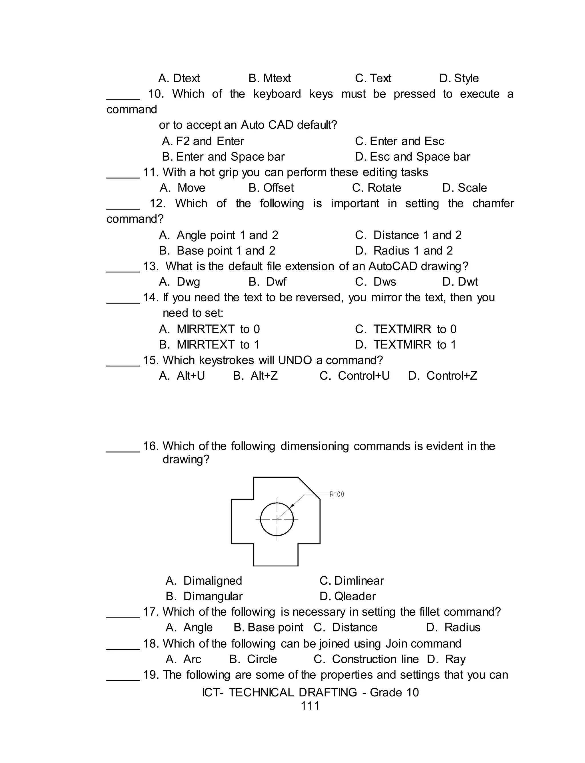
_____ 16. Which of the following dimensioning commands is shown in the
drawing?
A. Dimaligned
B. Dimangular
C. Dimlinear
D. Qleader
_____ 17. Which of the following is necessary in setting the fillet command?
A. Angle C. Distance
B. Base point D. Radius
_____ 18. Which of the following can be joined using the Join command
A. Arc B. Circle C. Construction line D. Ray
_____ 19. The following are some of the properties and settings that you can
save in a layout, except.
A. Plot scale C. Line weight
B. B. Paper size D. Drawing orientation
_____ 20. What command is used to specify settings in dimension style
manager?
A. Ddim B. Dimspec C. Dimalt D. Dimsize
Skills Assessment
Directions: Below are some important skills in computer-aided drawing.
Read the skills carefully, write “Not much,” if you are not really familiar, “A
little” and “A lot,” if you are familiar with the skill. Write your answers in your
notebook.
Skills in Preparing Computer-Aided Drawing No
Knowledge
A
Little
A
Lot
I can identify CAD software features according to the
software provider.
I know how to explore CAD working environment.
I know how to manipulate CAD features as per job
requirements.
5.
ICT- TECHNICAL DRAFTING- Grade 10
39
I can observe OHS policies and procedures when
preparing plan using CAD.
I know how to setup drawings according to standard
drawing scale and paper size.
I know how to prepare working drawings using CAD
software as per building standards.
Learning Goals and Targets
After reading the introduction and carefully answering the pre-
assessment skills test, you might have ideas of what to expect in this module.
Now prepare to set your goals and targets for this lesson by completing the
activity below.Write your answer in your notebook.
My goals are:
My targets are:
Goal 4
Goal 3
Goal 2
Goal 1
Target 1
Target 2
Target 3
6.
ICT- TECHNICAL DRAFTING- Grade 10
40
After creating your awareness about the learning goals and targets that you
are supposed to achieve, are you now ready to move on with this module? This will
include topics on the operation of CAD software and computer hardware.
This module will guide you to learn the basics of AutoCAD commands that
will enhance your skills in using the program. As you move along, you will learn to
use some of the unique techniques that give AutoCAD an advantage over manual
drawing.
Lesson 1. Operating CAD Software and Computer Hardware
This lesson is to enable the student to prepare and to familiarize
himself with the different things needed in operating the CAD software and
the computer hardware.
Some Technical Terms in Operating CAD Software and Hardware
Hardware - is all the physical equipment that makes up the computer system.
Software - is the set of programs and other related applications associated
with a computer system.
Central Processing Unit (CPU) - is the brain of the computer where most of
the “computing” takes place.
CAD Software and Hardware
Computer system can be broken down into two basic elements, the hardware
and the software.
THE HARDWARE
The hardware is the physical equipment that makes up the computer
system. It is divided into system hardware and peripherals. The system
7.
ICT- TECHNICAL DRAFTING- Grade 10
41
hardware includes the Central Processing Unit (CPU), the keyboard, the
monitor and primary storage memory (RAM), and the secondary storage
memory. Peripherals includes disk drives, mouse, digitizers, printers/plotters,
etc.
System Unit – The main part of a microcomputer, is sometimes called the
chassis. It includes the following parts: motherboard, microprocessor,
memory chips, buses, ports, expansion slots and cards.
Sample Tower Type System Unit
Source: computerit4u.com
The Central Processor Unit (CPU) –
is the brain of the computer where
most of the “computing” takes place. It
is also known as processor. It
performs all instructions and
calculations that are needed to
manage the flow of information.
Sample of CPU
8.
ICT- TECHNICAL DRAFTING- Grade 10
42
(Intel Core 2 Duo and AMD Athlon)
Source: products.yumecompare.com
Keyboard – is the principal device for communicating with your computer. All
keyboards have letter keys, punctuation keys, and a space bar which is
similar to the keys on a typewriter. Keyboards also have functions, numeric
and arrow keys in additional to Alt, Ctrl, and Enter keys.
Sample Keyboard
Source: news.techgenie.com
Monitor – it has a screen that displays information, such as the instruction
you send to your computer and the information and results your computer
sends back after interpreting your instruction. A color monitor will not display
color unless there is a video card fits inside your computer. The video card
determines the screen resolution and the number of colors that the monitor
can display.
9.
ICT- TECHNICAL DRAFTING- Grade 10
43
Sample Types of Monitor
Hard Disk Drive (HDD) – it also
known as hard drive. It is a
magnetic storage device that is
installed inside the computer. The
hard drive is used as a
permanent storage for data. In a
Windows computer, the hard
drive is usually configured as the
C: drive and contains the
operating system and
applications.
Hard Disk
Source: news.techgenie.com
Optical Drive – is a storage
device that uses lasers to read
data on the optical media. There
are three types of optical drives:
Compact Disc (CD), Digital
Versatile Disc (DVD) and Blu-ray
Disc (BD).
CD ROM
Source: www.ktclear.in
Mouse – is a small hand-held device used to control the cursor/crosshair on
the screen. They can be used to select an item by pointing to it and clicking a
button.
Sample Mouse
10.
ICT- TECHNICAL DRAFTING- Grade 10
44
Source: www.ztenterprise.com
Digitizer Tablet – is a graphics drawing tablet used for sketching new images
or tracing old ones. It is also called a "graphics tablet," where the user writes
or draws on the surface of the device with a wired or wireless pen or puck.
Often, mistakenly called a mouse, the puck is officially the "tablet cursor."
Sample Digitizer Tablet
Source: www.tutorialspoint.com
Printer – It is an output device that used to print information processed by
your computer. Printers and plotters varies in speed and output capabilities.
Sample Types of Printer
11.
ICT- TECHNICAL DRAFTING- Grade 10
45
Source: www.pcworld.co.uk
Plotter – an output device able to produce better quality drawings as
compared to printer, however the speed of plotter is generally slower than
printer.
Sample Plotter
Source: www.digitalcutterplotter.asia
THE SOFTWARE
The software is the set of programs, procedures, and related documentation
associated with a computer system. A program is a coded set of instructions
that interprets the information given to the computer with the keyboard or
mouse and directs the computer to carry a task. Softwares can be
categorized into two main groups: operating system software and application
software.
Operating System Software
The operating system software provides various levels of interaction (called
interface) between the computer and the user, as well as between the
computer and the application software.
12.
ICT- TECHNICAL DRAFTING- Grade 10
46
Application Software
The application software also called programs, has a specific use or task to
perform such as AutoCAD for Architectural drawings and layouts, Lotus 1-2-3
for business and marketing, Adobe Photoshop for image processing, and so
on.
Sample Application Software Logos
13.
ICT- TECHNICAL DRAFTING- Grade 10
47
Introduction to CAD System
Computer-aided design and drafting, otherwise known as CADD has
been around since 1964. However, it was not widely used until 1982, when
CAD system such as AutoCAD became available on microcomputers. ACAD
software uses either vector-based graphics to depict the objects of traditional
drafting, or may also produce faster graphics showing the realistic images of
the designed objects.
Computer-aided design (CAD), also known as computer-aided drafting
and design (CADD), is the use of computer systems to assist in the
creation, modification, and analysis of a design. It describes the process of
creating technical drawings with the use of computer software. CAD software
is used to increase the productivity, to improve the quality of design, and to
create a database for manufacturing.
CAD may be used to design curves and figures in two-dimensional
(2D) space; or curves, surfaces, and solids in three-dimensional (3D) space.
CAD is an important industrial art extensively used in many applications,
including automotive, shipbuilding, and aerospace industries; industrial and
architectural design; prosthetics; and many more. CAD is also widely used to
produce computer animation for special effects in movies, advertising, and
technical manuals.
Modern electronic drafting tools are often specialized computer-aided
design packages. Basic drafting tools are included in all CAD programs, but
some offer advanced automation are specifically designed for drafting and
architectural design. The tools that are right for you will depend on your
budget.
AutoCAD
An AutoCAD is a commercial product made by Autodesk, with
many versions, including one called AutoCAD Architecture.
AutoCAD Architecture has purpose-built features specifically
14.
ICT- TECHNICAL DRAFTING- Grade 10
48
designed for architectural drafting. In addition to design tools for initial
architectural conceptualization, it offers tools to make building renovations
faster and easier. The productivity tools include those that reflect the actual
design of walls and other structures. AutoCAD can maintain precise
dimensional spacing among components such as walls, beams, columns, and
doors. AutoCAD Architecture offers a library of pre-built components to help
speed up and automate the design and construction process.
Starting an AutoCAD
There are several ways of launching the AutoCAD program, depending
on the preferences and condition you may want to begin. Follow each of the
illustrated steps below:
1. From the Start Menu
- Click Start >Programs >Autodesk >AutoCAD from the Windows
Program Manager
2.
From a
desktop
shortcut or quick launch toolbar.
- Double-click the AutoCAD icon from your
desktop.
3. By opening the drawing file.
- Double-click the drawing file icon inside a folder or
in any location from your computer.
15.
ICT- TECHNICAL DRAFTING- Grade 10
49
The AutoCAD Working Environment
Like other windows-based applications, AutoCAD comes with a wide-
range of features used in many different aspects of a working drawing.
A. Menu Browser
– is a client-
software that
lets users read
or scan
documents on
the World Wide
Web.
A B E
L
GH
DC F
K
Main Work Area
Crosshair
r
J
I
16.
ICT- TECHNICAL DRAFTING- Grade 10
50
B. Quick Access Toolbar - is located along the top of the application
window (above or below the ribbon) and provides direct access to
common or defined set of commands like New, Open, Save, and Plot.
Procedure on how to add command/s to Quick Access Toolbar
1. Right-click the Quick Access toolbar >Customize Quick Access
toolbar.
2. Select the preferred commands.
3. Drag the selected commands to quick Access Toolbar.
C. Filename - The name of the current file you are working on.
D. Menu Bar – is the horizontal strip across the top of an application’s
window. Each word on the strip has a context sensitive drop-down
menu containing features and actions that are available for the
application in use.
E. Search Box – is a tool that allows you to search for a particular data or
document in a help file or to web.
F. Toolbars/Ribbon - provide a single, compact placement for
operations/tools that are relevant to the current workspace. By default
(in its original setting), it contains the Standard, Layers, Properties and
Styles toolbars.
17.
ICT- TECHNICAL DRAFTING- Grade 10
51
G. Command Line Bar - is where you enter the commands from the
keyboard and where the prompts are displayed. It has a text area
where all the previous commands are displayed.
H. Tray Settings/Info Bar - quickly search for a variety of information
sources, access product updates and announcements, and save topics
in the Info Center.
I. UCS – is found at the bottom left hand corner of the AutoCAD drawing
window. You will see a symbol like the one shown on the right. This is
called the UCS (User Coordinate System) icon and it is there to remind
you which is the X axis and which is the Y axis.
18.
ICT- TECHNICAL DRAFTING- Grade 10
52
J. WCS - By default when you start a new (blank) drawing you use the
World Coordinate System (WCS). This indicates your (0,0,0) point.
K. Draw Toolbar - Draw commands can be used to create new objects
such as lines and circles. Most AutoCAD drawings are composed
purely and simply from these basic components.
L. Modify Toolbar – is used to modify the basic drawing objects in some
way to suit the image you need. AutoCAD provides a whole range of
modify tools such as Move, Copy, Rotate and Mirror.
M. Working/Drawing Area – is the place where your drawings are
displayed and modified.
N. Crosshairs – is a type of cursor consisting of two lines that intersect
and are used to locate points and selects objects in your drawing.
O. Status Bar - displays the coordinate location of your crosshairs and
the current settings of grid, snap, and other drawing aids.
P. Dialog Box Launcher - displays the coordinate location of your
crosshairs and the current setting of grid, snap, and other drawing
aids.
19.
ICT- TECHNICAL DRAFTING- Grade 10
53
Suggested Activity 1
1. Label the parts of the AutoCAD Windows.
AutoCAD Coordinate Systems
A good understanding of how co-ordinates work in AutoCAD is
absolutely crucial if you are to make the best use of the program. If you are
not familiar with co-ordinates and co-ordinate systems, take some time to
familiarize yourself with the basic concepts.
20.
ICT- TECHNICAL DRAFTING- Grade 10
54
Co-ordinates fall into two types, namely Cartesian and Polar. They
can be either Absolute or Relative.
The Cartesian co-ordinate system is the standard co-ordinate
system. The position of a point can be described by its distance from two
axes, X and Y.
AutoCAD locates absolute X,Y coordinates with respect to the 0,0
point of the drawing — usually, its lower-left corner. AutoCAD
locates relative X,Y coordinates and relative polar coordinates with
respect to the previous point you picked or typed.
The Polar co-ordinates on the other hand, uses one distance and
one angle to describe the position of a point rather than the two distances.
The distance and angle measurements are made relative to an origin.
You will see how
AutoCAD uses all three
coordinate formats to draw
a pair of line segments that
start at the absolute
coordinates 2,1 (see
example) and then move to
the right 2 units and up 1
unit (@2,1) relative to the
first point.
Note in particular
how the first two coordinate
pairs use the same
numbers (2,1) but the
second pair defines a
different point because of
the leading @ symbol, then
(relative to that point) move
2 units at an angle of 60 degrees (@2<60).
Notice that the separator in the case of polar co-ordinates is the <
"less than" mathematical symbol.
Sample line segment using
AutoCAD Coordinate Systems
21.
ICT- TECHNICAL DRAFTING- Grade 10
55
Basic Drawing Tools
The Draw commands can be
used to create new objects such as
lines and circles. Most AutoCAD
drawings are composed purely and
simply from these basic components. A
good understanding of the Draw
commands is fundamental to the efficient use of AutoCAD.
The sections below cover the most frequently used Draw commands
such as Line, Polyline and Circle as well as the more advanced commands
like, Multiline and Multiline Style. As a newcomer to AutoCAD, you may wish
to skip the more advanced
commands in order to properly master the basics. You can always return to
this tutorial in the future after you have mastered the basics and become
more confident.
In common with most AutoCAD commands, the Draw commands can
be started in a number of ways. Command names or shortcuts can be
entered at the keyboard, commands can be started from the Draw pull-down
menu, shown on the right or from the Draw toolbar. The method you use is
dependent upon the type of work you are doing and how experienced a user
you are. Don't worry too much about this, just use whatever method you feel
the easiest or the most convenient at the time. Your drawing technique will
improve over time and with experience so don't expect to be working very
quickly at first.
The Line Command
With the Line command you can draw a simple line from one point to
another. When you pick the first point and move the cross-hairs to the
location of the second point you will see a rubber band line which shows you
where the line will be drawn when the second point is picked.
Command: LINE or L(enter)
Specify first point: (pick P1)
22.
ICT- TECHNICAL DRAFTING- Grade 10
56
Specify next point or [Undo]: (pick P2)
Specify next point or [Undo]: [press esc or enter]
The Polyline Command
The Polyline or Pline command is similar to
the line command except that the resulting object may be composed of a
number of segments which form a single object. In addition to the two ends a
polyline is said to have vertices (singular vertex) where intermediate line
segments join. In practice the Polyline command works in the same way as
the Line command allowing you to pick as many points as you like. As with
the Line command, you also have the option to automatically close a polyline
end to end. To do this, type C to use the close option instead of hitting. Follow
the command sequence below to see how this works.
Command: PLINE or PL[enter]
Specify start point: (pick P1)
Current line-width is 0.0000
Specify next point or [Arc/Half width/Length/Undo/Width]: (pick P2)
Specify next point or [Arc/Close/Half width/Length/Undo/Width]: (pick P3)
Specify next point or [Arc/Close/Half width/Length/Undo/Width]: (pick P4)
Specify next point or [Arc/Close/Half width/Length/Undo/Width]: (pick P5)
Specify next point or [Arc/Close/Half width/Length/Undo/Width]: (or C to
close)
The Rectangle Command
The Rectangle command is used to draw a rectangle whose sides are
vertical and horizontal. The position and size of the rectangle are defined by
picking two diagonal corners. The rectangle isn't really an AutoCAD object at
all. It is, in fact, just a closed polyline which is automatically drawn for you.
Command: RECTANG or REC[enter]
Specify first corner point or
[Chamfer/Elevation/Fillet/
Thickness/Width]: (pick P1)
23.
ICT- TECHNICAL DRAFTING- Grade 10
57
Specify other corner point or [Dimensions]: (pick P2)
The Rectangle command also has a number of options. Width works in
the same way as for the Polyline command. The Chamfer and Fillet options
have the same effect as the Chamfer and Fillet commands.
The Polygon Command
The Polygon command can be used to draw any regular polygon from
3 sides up to 1024 sides. This command requires four inputs from the user,
the number of sides, a pick point for the center of the polygon, whether you
want the polygon inscribed or circumscribed and then a pick point which
determines both the radius of this imaginary circle and the orientation of the
polygon.
Command: POLYGON or POL[enter]
Enter number of sides <4>: 5
Specify center of polygon or [Edge]: (pick P1 or type E to define by edge
length)
Enter an option [Inscribed in circle/Circumscribed about circle] <I>:
(To accept the inscribed default or type C for circumscribed)
Specify radius of circle: (pick P2 or enter exact radius)
The Donut Command
This command draws a solid donut shape, actually it's just a closed
polyline consisting of two arc segments which have been given a width.
AutoCAD asks you to define the inside diameter i.e. the diameter of the hole
24.
ICT- TECHNICAL DRAFTING- Grade 10
58
and then the outside diameter of the donut. The donut is then drawn in outline
and you are asked to pick the center point in order to position the donut. You
can continue picking center points to draw more donuts or you can hit to end
the command.
Command: DONUT or DO[enter]
Specify inside diameter of donut <0.5000>:
(pick any two points to define a diameter or enter the exact length)
Specify outside diameter of donut <1.0000>: (pick any two points to define a
diameter or enter the exact length)
Specify center of donut or <exit>: (pick P1)
Specify center of donut or <exit>: [Enter]
The Circle Command
The Circle command is used to draw circles. There are a number of
ways you can define the circle. The default method is to pick the center point
and then to either pick a second point on the circumference of the circle or
enter the circle radius at the keyboard.
Command: CIRCLE or C[enter]
Specify center point for circle or [3P/2P/Ttr (tan tan radius)]: (pick P1)
Specify radius of circle or [Diameter] <50.0195>: (pick P2 or enter the exact
radius)
As you can see from the command prompt above the default options
are always indicated in triangular brackets like so <Default> and command
options appear within square brackets like so [Option]. Each option is
separated by a forward slash like this /.
The Arc command
The Arc command allows you to draw an arc
of a circle. There are numerous ways to define an
25.
ICT- TECHNICAL DRAFTING- Grade 10
59
arc, the default method uses three pick points - a start point, a second point
and an end point. Using this method, the drawn arc will start at the first pick
point, pass through the second point and end at the third point.
Command: ARC or A[enter]
Specify start point of arc or [Center]: (pick P1)
Specify second point of arc or [Center/End]: (pick P2)
Specify end point of arc: (pick P3)
Note: It is also possible to create an arc by trimming a circle object.
The Spline Command
The Spline command creates a type of spline known as a non-uniform
rational B-spline, NURBS for short. A spline is a smooth curve that is fitted
along a number of control points. The Fit Tolerance option can be used to
control how closely the spline conforms to the control points. A low tolerance
value causes the spline to form close to the control points.
A tolerance of 0 (zero) forces the spline to pass through the control
points. The illustration on the right shows the effect of different tolerance
values on a spline that is defined using the same four control points, P1, P2,
P3 and P4. Splines can be edited after they have been created using the
SPLINEDIT command, Modify Object Spline from the pull-down menu. Using
this command, you can change the tolerance, add more control points move
control points and close splines, among other things. However, if you just
want to move spline control points, it
is best to use grips.
Command: SPLINE or SPL[enter]
Specify first point or [Object]: (Pick P1)
Specify next point: (Pick P2)
Specify next point or [Close/Fit
tolerance] <start tangent>: (Pick P3)
Specify next point or [Close/Fit
tolerance] <start tangent>: (Pick P4)
26.
ICT- TECHNICAL DRAFTING- Grade 10
60
Specify next point or [Close/Fit tolerance] <start tangent>:
Specify start tangent: (pick a point)
Specify end tangent: (pick a point)
Sample Spline Output
The Ellipse Command
The Ellipse command gives you a number of different creation options
whereas the default option has only three options, that is it picks that is, it
picks the two end points of an axis and then a third point to define the
eccentricity of the ellipse. After you have mastered the default option, try out
the ellipse command.
Command: ELLIPSE or EL[enter]
Specify axis endpoint of ellipse or [Arc/Center]: (pick P1)
Specify other endpoint of axis: (pick P2)
Specify distance to other axis or
[Rotation]: (pick P3)
The ellipse command can also be used to draw isometric circles.
Object Selection
Before you start to use the AutoCAD Modify commands, you need to
know something about selecting objects. All of the Modify commands require
27.
ICT- TECHNICAL DRAFTING- Grade 10
61
that you take one or more object selections. AutoCAD has a whole range of
tools which are designed to help you select just the objects you need.
Selecting Objects by Picking
Perhaps the most obvious way to select an object in AutoCAD is
simply to pick it. Those of you who have used other graphics based utilities
will be familiar with this concept. Generally all you have to do is place your
cursor over an object, click the mouse button and the object will be selected.
In this respect AutoCAD is no different from any other graphics utility.
When you start a Modify command such as ERASE, two things
happen. First, the cursor changes from the usual crosshairs to the pickbox
and second, you will see the "Select objects" prompt on the command line.
Both of these cues tell you that AutoCAD is expecting you to select one or
more objects.
To select an object, place the pickbox over a part of the object and left-
click the mouse. When the object has been picked it is highlighted in a
dashed line to show that it is part of the current selection and the command
line reports "1 found". You will now see the "Select objects" prompt on the
command line again. At this point you can continue adding more objects to
the current selection by picking them or you can press the Space Bar to
complete the selection.
When you pick one or more objects in response to the "Select objects"
prompt, you are effectively creating a selection set. Selection sets are an
important concept in AutoCAD because they can be used to great effect,
especially when drawings become larger or complicated.
28.
ICT- TECHNICAL DRAFTING- Grade 10
62
Crossing and Window Selection Method
The Crossing method is invoked by typing C at the "Select objects"
prompt and is a variation of the Window command. The command sequence
is exactly the same but objects are selected which lie entirely within the
window and those which cross the window border.
Command: (start one of the Modify commands such as ERASE)
Select objects: W
First corner: (pick first corner)
Specify opposite corner: (pick second corner)
Select objects: (at this point you can either select more objects or complete
the selection set, and continue with the current command.)
Adding and Removing Objects
AutoCAD provides two methods for adding and removing objects to
and from a selection set. As you know, objects can be added to a selection
set simply by picking them or by using one of the methods outlined above.
You can remove selected objects from a selection set just as easily by shift
picking. If you hold the Shift key down on the keyboard while picking a
selected object, that object will be deselected (removed from the current
selection set).
You can tell when a selected object has been deselected because it is
no longer highlighted. You can remove more than one object at a time by
29.
ICT- TECHNICAL DRAFTING- Grade 10
63
holding down the Shift key while using implied windowing. However, none of
the other selection options which require keyboard input will work using the
shift pick method.
Tips: When you are picking objects in a complex drawing, use the ZOOM
command transparently to make object selection easier. All Zoom options selected
from the toolbars are automatically transparent but if you invoke the command from
the keyboard you will need to enter zoom.
Modifying Objects
AutoCAD drawings are rarely completed simply by drawing lines, circles
etc. Most likely you will need to modify these basic drawing objects in some
way or another in order to create the image you need. AutoCAD provides a
whole range of modify tools such as Move, Copy, Rotate and Mirror. As you
can see, the command names are easily understandable. However, the way
these commands work is not always obvious.
The Erase Command
The Erase command is one of the simplest AutoCAD commands and is
one of the most used. The command erases (deletes) any selected object(s)
from the drawing. Remember you can always get deleted objects back by
typing U to undo, from the Standard toolbar or by using the OOPS command.
Command: ERASE or E[enter]
Select objects: (pick an object to erase)
Select objects: (to end the selection and erase the object)
30.
ICT- TECHNICAL DRAFTING- Grade 10
64
The Copy Command
The Copy command can be used to create one or more duplicates of any
drawing object or objects which you have previously created. Copy is a very
useful and time-saving command because you can create very complex
drawing elements and then simply copy them as many times as you like.
Command: COPY or CO[enter]
Select objects: (pick object to copy, P1)
Select objects: (to end selection)
Specify base point or displacement, or [Multiple]: (pick P2 or M for multiple
copies)
Specify second point of displacement or <use first point as displacement>:
(pick P3)
The multiple option allows you to create additional copies of the selected
object(s) by picking as many new points as you like. To end a multiple copy,
just hit the key.
The Mirror Command
The Mirror command allows you to mirror selected objects in your
drawing by picking them and then defining the position of an imaginary mirror
line using two points.
Command: MIRROR or MI[enter]
Select objects: (pick object to mirror, P1)
Select objects: (to end selection)
Specify first point of mirror line: (pick P2)
Specify second point of mirror line: (pick P3)
Delete source objects? [Yes/No] <N>: (for No to keep the original object)
31.
ICT- TECHNICAL DRAFTING- Grade 10
65
The Offset Command
Offset is probably one of the most useful commands for constructing
drawings. The Offset command creates a new object parallel to or concentric
with a selected object. The new object is drawn at a user defined distance
(the offset) from the original and in a direction chosen by the user with a pick
point. You can offset lines, arcs, circles, ellipses, 2D polylines, xlines, rays
and planar splines.
Command: OFFSET or O[enter]
Specify offset distance or [Through] <1.0000>: 10 (specify distance)
Select object to offset or <exit>: (select object, P1)
Specify point on side to offset: (pick direction, P2)
Select object to offset or <exit>: (to end or select another object to offset)
The Move Command
32.
ICT- TECHNICAL DRAFTING- Grade 10
66
The Move command works in a similar way to the Copy command
except that no copy is made, the selected object(s) is simply moved from one
location to another.
Command: MOVE or M[enter]
Select objects: (pick object to move, P1)
Select objects: (to end selection)
Specify base point or displacement: (pick P2)
Specify second point of displacement or <use first point as displacement>:
(pick P3)
Note: The Copy command, the two pick points, P2 and P3 are used only to
indicate the distance and direction of movement.
The Rotate Command
The Rotate command allows an object or objects to be rotated about a point
selected by the user. AutoCAD
Command: ROTATE or RO[enter]
Current positive angle in UCS: ANGDIR=counterclockwise ANGBASE=0
Select objects: (pick object to rotate, P1)
Select objects: (to end selection)
Specify base point: (pick base point, P2)
33.
ICT- TECHNICAL DRAFTING- Grade 10
67
Specify rotation angle or [Reference]: (pick second point, P3 or enter angle)
Remember, by default, AutoCAD angles start at 3 o'clock and increase in
an anti-clockwise direction. The "ANGDIR" and "ANGBASE" variables remind
you of this. If you want to rotate in a clockwise direction you can enter a
negative angle by using a minus sign.
Note: You can change the angle direction and the base angle using the Units
command, Format Units… from the pull-down menu. Click the "Clockwise" check box
to change the direction and click the "Direction…" button to set the base angle.
The Scale Command
The Scale command can be used to change the size of an object or group
of objects. You are prompted for a pick point about which the selection set will
be scaled. Scaling can then be completed by picking a second point (not
always easy because it can sometimes be difficult to precisely control the
scaling) or by entering a scale factor at the keyboard. For example a scale
factor of 2 will double the size of the objects in the selection set and a factor
of 0.5 will reduce them into half.
Command: SCALE or SC[enter]
Select objects: (pick objects to be scaled, P1)
Select objects: (to end selection)
Specify base point: (pick base point, P2)
Specify scale factor or [Reference]: (pick second point, P3 or enter scale
factor)
34.
ICT- TECHNICAL DRAFTING- Grade 10
68
As shown above, the original tree symbol has been enlarged by
dynamically scaling it using pick points to determine the change in scale. If
you want to scale an object precisely, it is much easier to enter a scale factor
using the keyboard.
The Stretch Command
The Stretch command can be used to move one or more vertices of an
object while leaving the rest of the object unchanged. In the example below, a
rectangle has been stretched by moving one vertex to create an irregular
shape.
Command: STRETCH or S[enter]
Select objects to stretch by crossing-window or crossing-polygon...
Select objects: (pick first point of crossing window)
Specify opposite corner: (pick second point of window)
Select objects: (to end selection)
Specify base point or displacement: (pick base point)
Specify second point of displacement: (pick second point)
35.
ICT- TECHNICAL DRAFTING- Grade 10
69
Note: To select vertices to stretch, you must use a crossing window or polygon.
The Trim Command
The Trim command can be used to trim a part of an object. In order to
trim an object you must draw a second object which forms the "cutting edge".
Cutting edges can be lines, xlines, rays, polylines, circles, arcs or ellipses.
Blocks and text cannot be trimmed or used as cutting edges.
Command: TRIM or TR[enter]
Current settings: Projection=UCS Edge=None
Select cutting edges ...
Select objects: (select the cutting edge, P1)
Select objects: (to end cutting edge selection)
Select object to trim or shift-select to extend or [Project/Edge/Undo]:
(pick the part of the square which you want to trim, P2)
Select object to trim or shift-select to extend or [Project/Edge/Undo]:
(pick the circle, P3)
Select object to trim or shift-select to extend or [Project/Edge/Undo]: (to end)
Note: Notice that at each trimming step you are given the option to undo the
previous trim. This can be very useful if you inadvertently pick the wrong object.
The Chamfer Command
36.
ICT- TECHNICAL DRAFTING- Grade 10
70
The Chamfer command enables you to create a chamfer between any two
non-parallel lines as in the illustration below or any two adjacent polyline
segments. Usually, the Chamfer command is used to set the chamfer
distances before drawing the chamfer. Follow the command sequence below
where the chamfer distances are changed to 20 before the chamfer is made.
Command: CHAMFER or CHA[enter]
(TRIM mode) Current chamfer Dist1 = 10.0000, Dist2 = 10.0000
Select first line or [Polyline/Distance/Angle/Trim/Method]: D (to set distances)
Specify first chamfer distance <10.0000>: 20 (enter required distance)
Specify second chamfer distance <20.0000>:
(first distance value or enter a different value)
Select first line or [Polyline/Distance/Angle/Trim/Method]: (pick P1)
Select second line: (pick P2)
The chamfer is made and the command ends.
Note: Notice from the command sequence that there are a number of options
which can be used to control the way the Chamfer command behaves.
The Fillet Command
The Fillet command is a very useful tool which allows you to draw an arc
between two intersecting lines or adjacent polyline segments. You need first
to use the command to set the required radius and then a second time to
select the two lines.
37.
ICT- TECHNICAL DRAFTING- Grade 10
71
Command: FILLET or F[enter]
Current settings: Mode = TRIM,
Radius = 10.0000
Select first object or
[Polyline/Radius/Trim]: R
Specify fillet radius <10.000>: 25
Select first object or
[Polyline/Radius/Trim]: (pick P1)
Select second object: (pick P2)
The Fillet command can also be
used to fillet arcs and circles.
The "Polyline" option also allows
you to fillet all vertices of a
polyline with a single command.
Tips: Make sure that the
radius you specify will fit the objects
you select, otherwise the fillet
command will not work.
The Array Command
Using the Array command, you can duplicate existing objects in a
rectangle or circular (polar) pattern. You can select which type of array to use
in the Array dialog box. Click the Rectangular or Polar options to see point,
distance, and method requirements for each type.
The following illustration shows a rectangular and polar array.
Command: ARRAY or AR[enter]
Ribbon: Home tab > Modify panel > Array
Note: Do not confuse this command with the 3D Array command.
Menu Browser: Modify > Array
38.
ICT- TECHNICAL DRAFTING- Grade 10
72
Array Dialog Box: Rectangular Array
1. Click to select the object(s) to include in the array.
2. Enter the number of rows (horizontal patterns) for the array.
3. Enter the number of columns (vertical patterns) for the array.
4. Enter a distance to offset each row. Use the simulated preview window
to see the direction of the pattern.
5. Enter a distance to offset each column.
6. Enter an angle for the pattern.
7. Click Preview to preview the array. Preview is not available until you
select an object or objects for the array.
39.
ICT- TECHNICAL DRAFTING- Grade 10
73
Array Dialog Box: Polar Array
1. Click to select the object(s) to include in the array.
2. Enter the center point's coordinates in the X and Y fields or click the
Select Point icon to select a center point in the drawing window.
3. Select the method for calculating the polar array.
- Total number of items and angle to fill.
- Total number of items and angle between items.
- Angle to fill and angle between items.
4. Enter the total number of items for the array. This includes the original
object.
5. Enter the total angle for the array. A negative number creates the array
in a clockwise direction.
6. Select to rotate each object as it is placed in the array.
40.
ICT- TECHNICAL DRAFTING- Grade 10
74
Drawing Aids
Drawing with AutoCAD is really just like drawing on a drawing board. Most
new comers to Computer Aided Design assume that they will need to learn
how to draw all over again. In fact, many of the drawing aids that AutoCAD
provides are analogous to traditional drafting tools
Ortho Mode
Ortho is short for orthogonal, which means either vertical or horizontal.
Like the other options on the status bar, Ortho is not really a command, it is a
drawing mode which can either be turned on or off. Ortho mode can be
toggled on or off in one of three ways.
Command: ORTHO
Enter mode [ON/OFF] <OFF>: (type ON or OFF)
The Drawing Grid
The drawing grid is a regular pattern of dots displayed on the screen
which acts as a visual aid, it is the equivalent of having a sheet of graph
paper behind your drawing on a drawing board. You can control the grid
spacing, so it can give you a general idea about the size of drawn objects. It
can also be used to define the extent of your drawing.
Command: GRID
Specify grid spacing(X) or [ON/OFF/Snap/Aspect] <10.000>: (enter grid
spacing)
Snap Mode
Snap mode takes AutoCAD one step further than the drawing board. With
Snap mode turned on AutoCAD only allows you to pick points which lie on a
regular grid. The Snap grid is completely independent of the display grid.
Command: SNAP or SN[enter]
Specify snap spacing or [ON/OFF/Aspect/Rotate/Style/Type] <10.0000>:
(enter the required snap spacing in drawing units)
41.
ICT- TECHNICAL DRAFTING- Grade 10
75
Units and Scales
Among the most important concepts that newcomers to AutoCAD need to
come to grips with are those of drawing scales and drawing units. You cannot
start creating sensible drawings with AutoCAD until you are familiar with
scale, units and the commands you use to control them.
When drawing on paper you must decide to draw and say, 1:20 or 1:200
depending upon the size of the object that you are drawing so that your
scaled drawing will fit on the drawing sheet, be that A3 or A1. In AutoCAD you
do not need to decide upon a drawing scale until you come to print the
drawing and because the scaling of your drawing takes place at the printing
stage, you can create drawings at a scale of 1:1.
Units Control
When you start the Units command, the first thing you see is the Drawing
Units dialogue box, shown on the next page at the right. The dialogue box is
divided into four main sections. The upper two are "Length", which refers to
linear units and "Angles", referring to angular units. Settings for linear units
and angular units can be made independently and in each case, you can
control both the type and precision.
Command: units
Object Snap
The main reason for this flexibility in using the Object Snaps is that they
are used very frequently. Experienced AutoCAD users will always use Object
Snaps because they are the only way to make sure that the objects they are
drawing are drawn accurately.
You must practice using Object Snaps until they become second nature to
you. There are thirteen (13) Osnaps in all and although they are all useful in
certain situations you will probably find yourself using about half of them on a
regular basis and the other half in special circumstances.
42.
ICT- TECHNICAL DRAFTING- Grade 10
76
However, it's a good idea to get to know all of the Osnaps so that you can
plan your drawing, knowing all of the tools at your disposal. A sensible use of
Osnaps is the best way to improve your drawing efficiency.
Endpoint Osnap
The Endpoint Osnap breaks to the end
points of lines and arcs and to polyline vertices.
This is one of the most useful and commonly
used Osnaps.
Command: END
Short-cut: Shift + Right Click Endpoint
Midpoint Osnap
The Midpoint Osnap breaks to the mid
points of lines and arcs and to the mid-point of
polyline segments.
Command: MID
Short-cut: Shift + Right Click Midpoint
Intersection
The Intersection Osnap snaps to the physical intersection of any two
drawing objects (i.e. where lines, arcs or circles etc. cross each other) and to
Polyline vertices. However, this osnap can also
be used to snap to intersection points which do
not physically exist. This feature is called the
Extended Intersection (see the illustration on
the right). To use the apparent intersection
feature, you must pick two points to indicate
which two objects should be used.
Extension
43.
ICT- TECHNICAL DRAFTING- Grade 10
77
The Extension Osnap enables you to snap to some point along the
imaginary extension of a line, arc or polyline segment. To use this osnap, you
must hover the cursor over the end of the line you want to extend. When the
line end is
found, a small cross appears at the endpoint and a dashed extension line is
displayed from the endpoint to the cursor, providing the cursor remains close
to the extension.
Command: EXT
Short-cut: Shift + Right Click Extension
Parallel
The Parallel Osnap is used to draw a line
parallel to any other line in your drawing. In
operation, this osnap is slightly less intuitive than
some of the others. To draw a parallel line, first
start the Line command, specify the first point
when prompted and then start the Parallel
Osnap. Hover the cursor over an existing line
until you see the Parallel snap marker.
Now, move the cursor close to a parallel position and a dotted line will
appear, indicating the parallel. You can now pick the second point of your
line. The Snap Tip also includes a relative polar co-ordinate.
Node
The Node Osnap snaps to the center of a Point object. This osnap can be
useful if you have created a number of Points with the Measure or Divide
commands. You could, for example insert a number of regularly spaced tree
symbols (blocks) along a line by using the Node Osnap for the insertion point
of each block.
Command: NODE
Short-cut: Shift + Right Click Node
44.
ICT- TECHNICAL DRAFTING- Grade 10
78
Tips:
When you are drawing, take a few moments to consider how you will
construct each part of the drawing and decide which Osnaps you will
use before starting to work. There is always more than one way to
draw anything in AutoCAD but the quickest, most accurate and the
most efficient way always requires the use of one or more of the
Osnap tools.
Dock the Object Snap toolbar to your drawing window for quick access
to the Osnaps. You will be using them all the time, one-click access is
essential. See Object Snaps to find out how to display the Object Snap
toolbar. To dock the toolbar, click on the toolbar title and drag it to the
edge of the drawing window.
Creating AutoCAD Blocks
In this lesson you will be introduced to creating AutoCAD blocks to
create your AutoCAD library for symbols. By definition, a block is a collection
of objects (lines, arcs, circles, text, etc.) that form a more complex entity that
normally represents an object in the real world, e.g. a door, a chair, a window,
a computer.
There are many advantages to using blocks, here are the major ones:
A. Blocks are a single entity. You can modify (move, copy, rotate) a block
by selecting only one object in it.
45.
ICT- TECHNICAL DRAFTING- Grade 10
79
B. Using blocks can help keep your file size-down. AutoCAD stores block
definitions in its database. When you insert a block, AutoCAD only
stores the name of the block, its location (insertion point), scale and
rotation. This can be very noticeable in large drawing.
Here are the commands that you will need for using blocks in this lesson:
Command Keystroke Icon Location Result
Block wmake / B Home > Block
> Create
Creates a block from separate
entities (internal to current drawing)
Write
Block
wblock / W None None Creates a block and writes it to a file
(external)
Insert insert / I Home > Block
> Insert
Inserts a block (internal or external)
Explode explode / X Home > Modify
> Explode
Explodes a block or other compound
object into its component parts
Steps in Creating AutoCAD Blocks
1. Lunch the AutoCAD.
2. Create a new initial layer.
3. Name it according to the standards.
4. Make the Zero Layer current.
NOTE: Zero Layer has special properties. When creating blocks, if the
objects in the block are drawn on Zero layer, they will assume the properties
of the current layer when they are inserted.
5. Select one of the symbols that you want to draw. This
example uses only arc/circle and line command.
6. Pull down the menu or the icon and a dialogue box
appears.
7. Enter information you want to include.
46.
ICT- TECHNICAL DRAFTING- Grade 10
80
8. The first thing that you want to do is give your block a name.
Type Ceiling Outlet Fixture in the edit box beside Block Name. Some
names may need to be more descriptive, such as part number, or size.
Give your block a name by typing Ceiling Outlet Fixtures.
9. Pick the Pick Point button and then pick the midpoint of the bottom
line. Make sure that the retain button is selected, this will keep your
objects on the screen as individual objects. If you don't select a base
point, your block will default to 0,0,0 and you will insert all your blocks
at the same location - the origin.
(You will see in a moment that selecting the Pick Point with blocks is very
important when you later insert them into the drawing - always pick a point
that will allow you to place the block easily.)
10. Pick the Select Objects button and then select all the parts of your
drawing/object and press <ENTER>.
11. Select the drawing units you used to create the original object.
12. Pick the OK Button and the dialog box closes. Your drawing file will
contain a “Block Definition” called Ceiling Outlet Fixture.
Congratulations, you have created your first block!
Ceiling Outlet
Ceiling OutletFixture
47.
ICT- TECHNICAL DRAFTING- Grade 10
81
If the default radio button "Convert to block" was checked, move your
mouse over the objects and you will see that they all highlight - signifying that
it is now one object.
Inserting the AutoCAD Blocks
Once a block is created you may insert it by typing, I <ENTER>.
Change to the Ceiling Outlet Fixture Layer. You will see this dialog box on the
screen:
By default, all the options you need are pre-selected. Since you only
have one block in your drawing, its name is displayed.
Make sure that the Insertion Point - Specify On-screen box is checked, and
the Explode button is not checked. The Scale - Specify On-screen should
not be checked. Then press the OK button. Pick anywhere on your screen
and you will see the block appear. Notice how the block that you drew on the
white Zero Layer is now Red and on the Ceiling Outlet Fixtures layer.
You may now insert a Ceiling Outlet Fixture on every floor plans in your
drawing. You can also copy the block instead of re-inserting each time, but
make sure you know how to insert.
Ceiling OutletFixture
48.
ICT- TECHNICAL DRAFTING- Grade 10
82
AutoCAD COMMON FUNCTION KEYS
F1: Display Help F7: Toggles GRID mode
F2: Toggles the Text Window F8: Toggles ORTHO mode
F3: Toggles OSNAP F9: Toggles SNAP mode
F4: Toggles Tablet mode F10: Toggles Polar Tracking
F5: Toggles ISOPLANE F11: Toggles Object Snap Tracking
F6: Toggles Dynamic UCS F12: Toggles Dynamic Input
SPECIAL KEY FUNCTIONS
Escape Key – Cancels the current command, menu or dialogue box.
Enter Key – Ends a command, or will repeat the previous command if blank.
Space Bar – Same as the Enter Key, except when entering key.
CTRL+0: Toggles Clean Screen CTRL+PAGE DOWN: Move to the next
CTRL+1: Toggles the Properties palette layout tab to the right of the current
tab
CTRL+2: Toggles the Design Center palette CTRL+D: Toggles Dynamic UCS
CTRL+3: Toggles the Tool Palettes windowCTRL+E: Cycles through isometric
planes
CTRL+4: Toggles the Sheet Set Manager CTRL+F: Toggles running object
snaps
CTRL+6: Toggles the dbConnect Manager CTRL+G: Toggles the grid
CTRL+7: Toggles the Markup Set Manager CTRL+H: Toggles PICKSTYLE
CTRL+8: Toggles the QuickCalc calculator CTRL+I: Toggles COORDS
palette CTRL+J;CTRL+M: Repeat the last command
CTRL+9:Toggles the Command Window (pressing Enter does the same)
CTRL+A: Selects all objects in the drawing CTRL+L: Toggles Ortho mode
CTRL+SHIFT+A: Toggles Groups CTRL+N: Creates a new drawing
CTRL+B: Toggles Snap mode CTRL+O: Opens an existing drawing
CTRL+C: Copies an objects to Clipboard CTRL+P: Prints/plots the current
drawing
CTRL+SHIFT+C: Copies objects to CTRL+R: Cycles through layout
viewports
Clipboard with Base Point CTRL+S: Saves the current drawing
CTRL+X: Cuts object to Clipboard CTRL+T: Toggles Tablet mode
CTRL+Y:Cancels the preceding Undo action CTRL+SHIFT+V:Pastes data from the
CTRL+V: Pastes data from the Clipboard Clipboard as a Block
CTRL+Z: Reverses the last action
CTRL+CTRL+S: Opens the Save As dialog box
CTRL+[;CTRL+: Cancels the current Command (pressing Esc does the same)
49.
ICT- TECHNICAL DRAFTING- Grade 10
83
CTRL+ PAGE UP: Moves to the next layout Tab to the left of the current tab
Now, you can simply draw lines by picking their position from the
workspace. If you want to draw lines with precise direction and length you can
use the Direct Distance Entry or the Relative Polar Coordinate.
Suggested Activity 1
Directions: Using the given drawing menu below, perform the following
tasks.
A. Draw Menu: LINE or L[enter]
By Picking
Command: LINE
Specify first point: (pick 1)
Specify next point or [Undo]: (pick 2)
Specify next point or [Undo]: (pick 3)
Specify next point or [Undo]: (pick 4)
Specify next point or [Undo]: press Enter Key
By Direct Distance Entry
Command: LINE
Specify first point: (pick)
Specify next point or [Undo]: (activate ortho enter the distance) 100
Specify next point or [Undo]: press Enter Key
B. Draw Menu: PLINE or PL[enter]
By Direct Distance Entry and Polar Coordinate
Command: PLINE
Specify start point: (pick 1)
Current line-width is 0.0
Specify next point or […]: (ortho ON and drag the mouse for desired
position) 400
Specify next point or […]: 200
Specify next point or […]: @300<30
Specify next point or […]: press Enter Key
Process
50.
ICT- TECHNICAL DRAFTING- Grade 10
84
C. Draw Menu: ARC or A[enter]
Command: ARC or A (press enter key)
Specify start point of arc or [Center]: (pick 1)
Specify second point of arc or [Center/End]: (pick 2)
Specify end point of arc: (pick 3)
Suggested Activity 2
1. Directions: With the suggested commands, draw the traffic signs
below in free size.
Suggested Commands:
REC, OFFSET, LINE, ROTATE, FILLET, HATCH, ERASE, ARC, CIRCLE,
TRIM, OSNAP, & ORTHO
Note: Assessment tool – Performance Rubrics (Refer to Appendix A)
51.
ICT- TECHNICAL DRAFTING- Grade 10
85
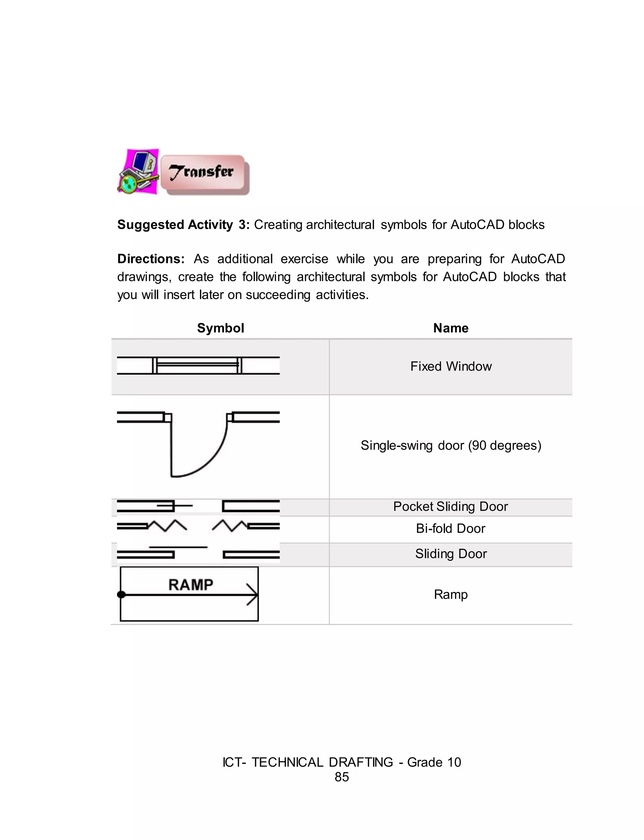
Suggested Activity 3: Creating architectural symbols for AutoCAD blocks
Directions: As additional exercise while you are preparing for AutoCAD
drawings, create the following architectural symbols for AutoCAD blocks that
you will insert later on succeeding activities.
Symbol Name
Fixed Window
Single-swing door (90 degrees)
Pocket Sliding Door
Bi-fold Door
Sliding Door
Ramp
52.
ICT- TECHNICAL DRAFTING- Grade 10
86
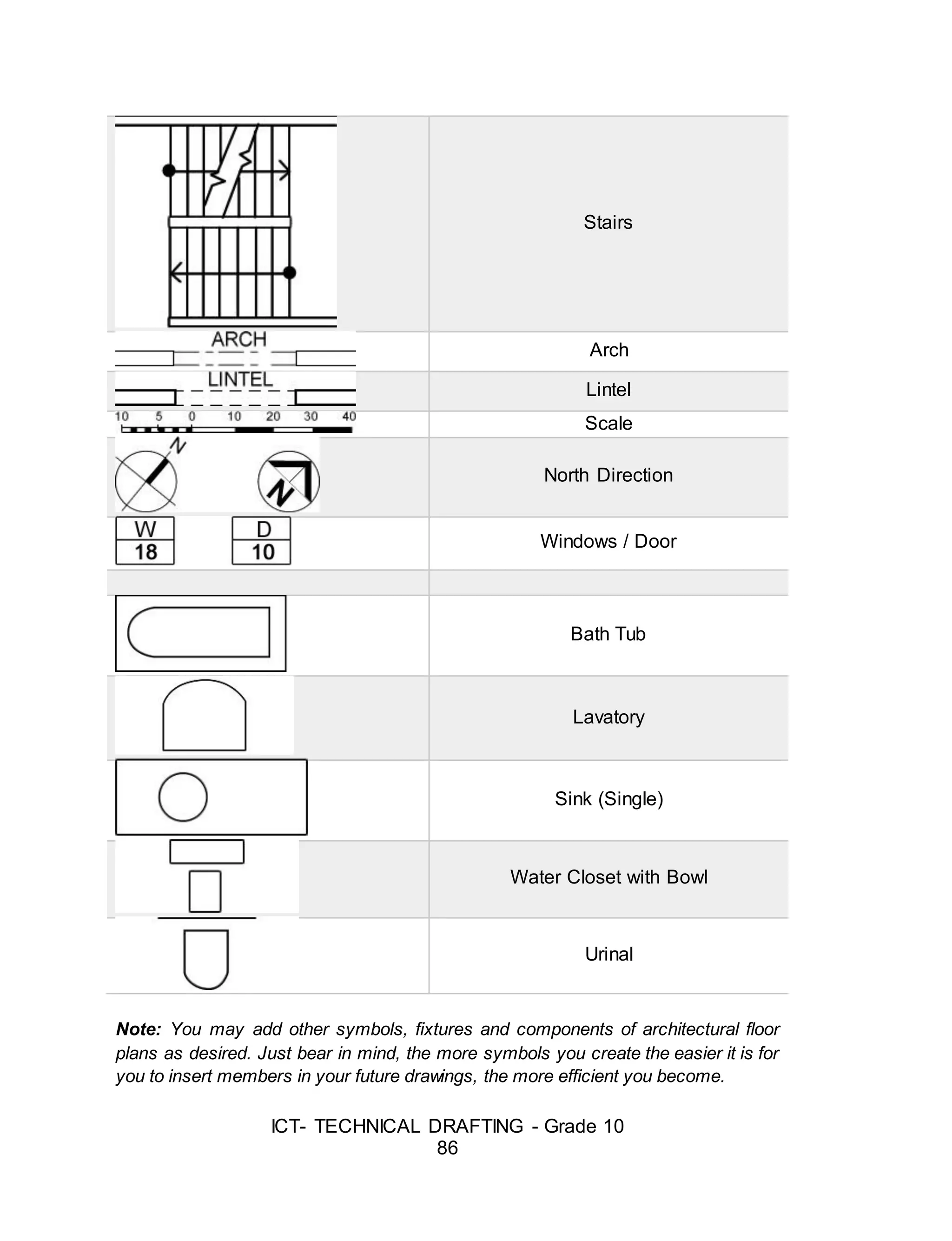
Stairs
Arch
Lintel
Scale
North Direction
Windows / Door
Bath Tub
Lavatory
Sink (Single)
Water Closet with Bowl
Urinal
Note: You may add other symbols, fixtures and components of architectural floor
plans as desired. Just bear in mind, the more symbols you create the easier it is for
you to insert members in your future drawings, the more efficient you become.
53.
ICT- TECHNICAL DRAFTING- Grade 10
87
Lesson 2: Preparing a Plan Using CAD
Introduction
Setting Up AutoCAD to Work With Architectural Drafting Style
You will need to make some changes to AutoCAD to use it as a
drafting tool for architectural drawings. AutoCAD “out-of-the-box” is set up
primarily for mechanical drafting (drawing small parts for machinery using the
metric system). This type of drafting is commonly practiced in the world.
However, making drawings of a building is quite different from making
drawings of an automobile part. Not only is the scale of the object drawn very
different, but the conventions of drafting are significantly different between
architectural and mechanical parts. In order to make the drafting environment
correct for architectural drafting conventions, several changes must be made.
These changes are relatively simple to accomplish, and involve the following
two types of set-up.
1. Creating a Template File that has desirable variables set, as well as
layers, text styles, dimension styles, layouts and plotting standards
created specifically for architectural drafting purposes. Your Template
file can then be used to open new drawings to eliminate having to set
up these changes again in the future.
54.
ICT- TECHNICAL DRAFTING- Grade 10
88
2. Creating a User Profile will save the way you want the screen to look
and where AutoCAD will search for files. Your personal Profile can be
loaded when you start a new AutoCAD session at whatever computer
you are working.
Template Files
When you begin a drawing using AutoCAD, you will be drawing in an
environment which has pre-set variables setup by Autodesk for what they
consider to be the most common use. However, the settings which come with
the software "out of the box" are not good for drawings used in the
architectural and interior design industry, so they must be changed by you to
comply with standard drafting conventions in those fields.
Using Template Files
To use a template file to begin a new drawing,
- Click the Menu Browser >Save As…>Drawing Template> specify
the filename, then Save.
Templates have the filename extension of *.dwt. The easiest way to
make your standard settings permanent for later reuse is to create your own
Template File. Begin a new drawing, set the drawing variables as you want
them to be set, and then save the drawing as a "Template" file for reuse on
future drawings. This new file will have no "entities" in it (lines, arcs, or
circles), but it will include the following variables:
- Your list of LAYERS, with associated line types, colors, and
line weights
- Text styles
- Dimension styles
- AutoCAD variable settings
- Layout settings
- Viewport(s)
55.
ICT- TECHNICAL DRAFTING- Grade 10
89
- Name of each viewport
- Scale of each viewport
- Plotting parameters of each viewport, such as what printer to
plot to
- paper size,
- plot scale
- drawing orientation,
- plot style table (pen assignments)
- Title sheet information etc.
Suggested Activity 1
A. IDENTIFICATION.
Directions: Identify shortcut of the following commands. Write your
answer in a separate sheet of paper or in your notebook.
B. Directions: Choose the best command from inside below that is
applicable to the drawing. The given are on the left side and the output
are on the right side. Write your answer in a separate sheet of paper
or in your notebook.
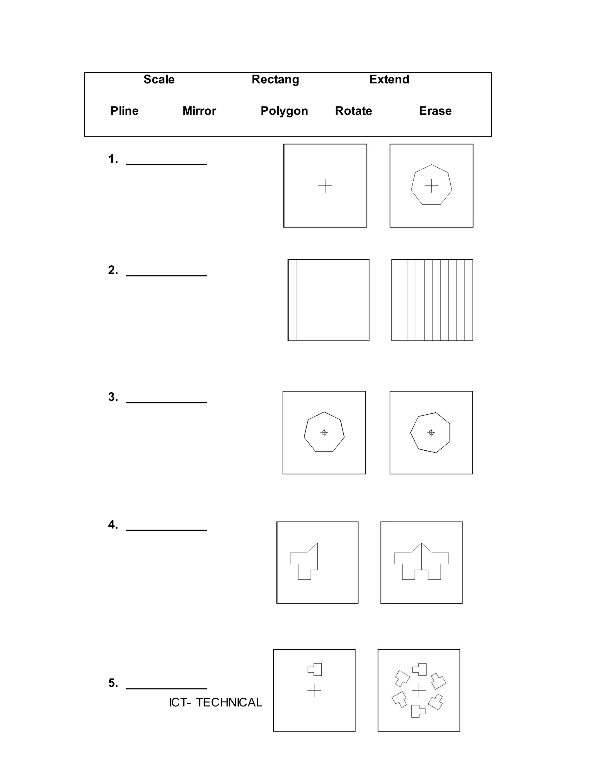
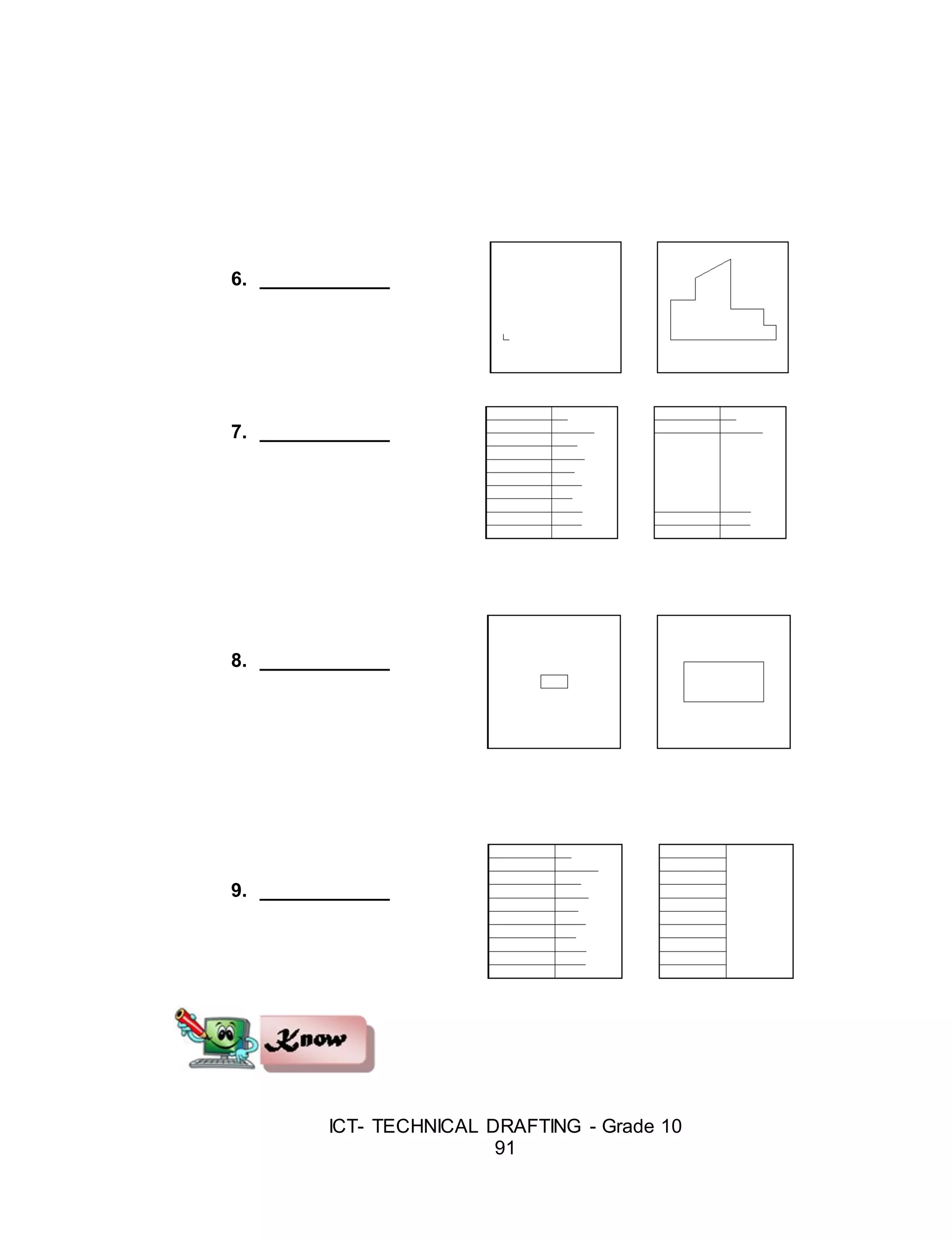
Line Array Trim Offset Copy
1. Move 11. Scale
2. Spline 12. Stretch
3. Copy 13. Fillet
4. Offset 14. Arc
5. Polyline 15. Erase
6. Donuts 16. Circle
7. Polygon 17. Trim
8. Snap 18. Extend
9. Rotate 19. Chamfer
10. Ellipses 20. Array
ICT- TECHNICAL DRAFTING- Grade 10
92
Layers
Layers are key components for organizing AutoCAD drawings. Layers
are ways of managing, tidying, and also controlling the visual layout of a
drawing. A whole section of a drawing can be turned on or off, or simply one
aspect can be controlled - text for example. This is all done by using layers
within AutoCAD.
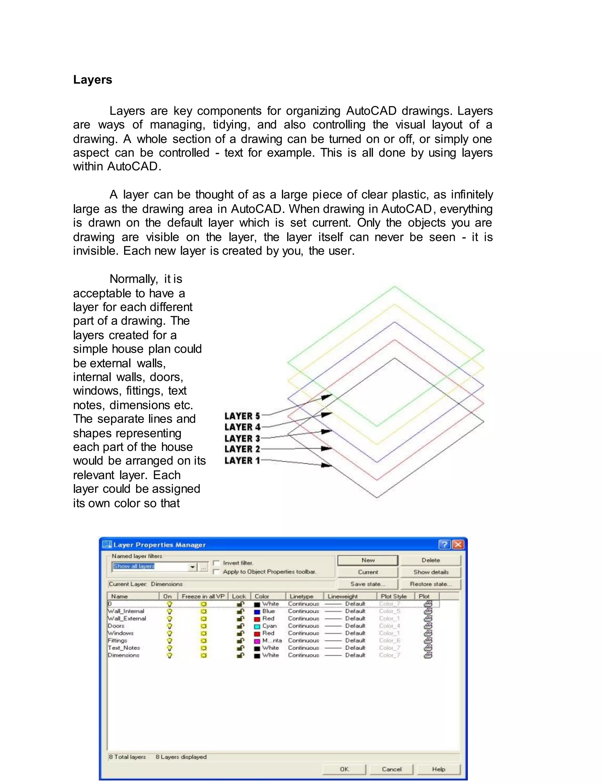
A layer can be thought of as a large piece of clear plastic, as infinitely
large as the drawing area in AutoCAD. When drawing in AutoCAD, everything
is drawn on the default layer which is set current. Only the objects you are
drawing are visible on the layer, the layer itself can never be seen - it is
invisible. Each new layer is created by you, the user.
Normally, it is
acceptable to have a
layer for each different
part of a drawing. The
layers created for a
simple house plan could
be external walls,
internal walls, doors,
windows, fittings, text
notes, dimensions etc.
The separate lines and
shapes representing
each part of the house
would be arranged on its
relevant layer. Each
layer could be assigned
its own color so that
59.
ICT- TECHNICAL DRAFTING- Grade 10
93
everything drawn on that layer to be of the same color.
Note: Layers are controlled by the layer properties manager button which
is located on the object properties toolbar.
The layer property manager is where all the layers are controlled. The
layout above shows a typical use of layers.
From the layer property manager we can:
Add a New Layer - Press the New button to create a new layer.
Delete a Layer - Press the Delete button to delete the selected layer.
Set Current layer - Press the Current button to set the selected layer
current. All objects drawn will then be drawn on this current layer.
Show Details - Press the Show details button to see more detailed
information about the selected layer.
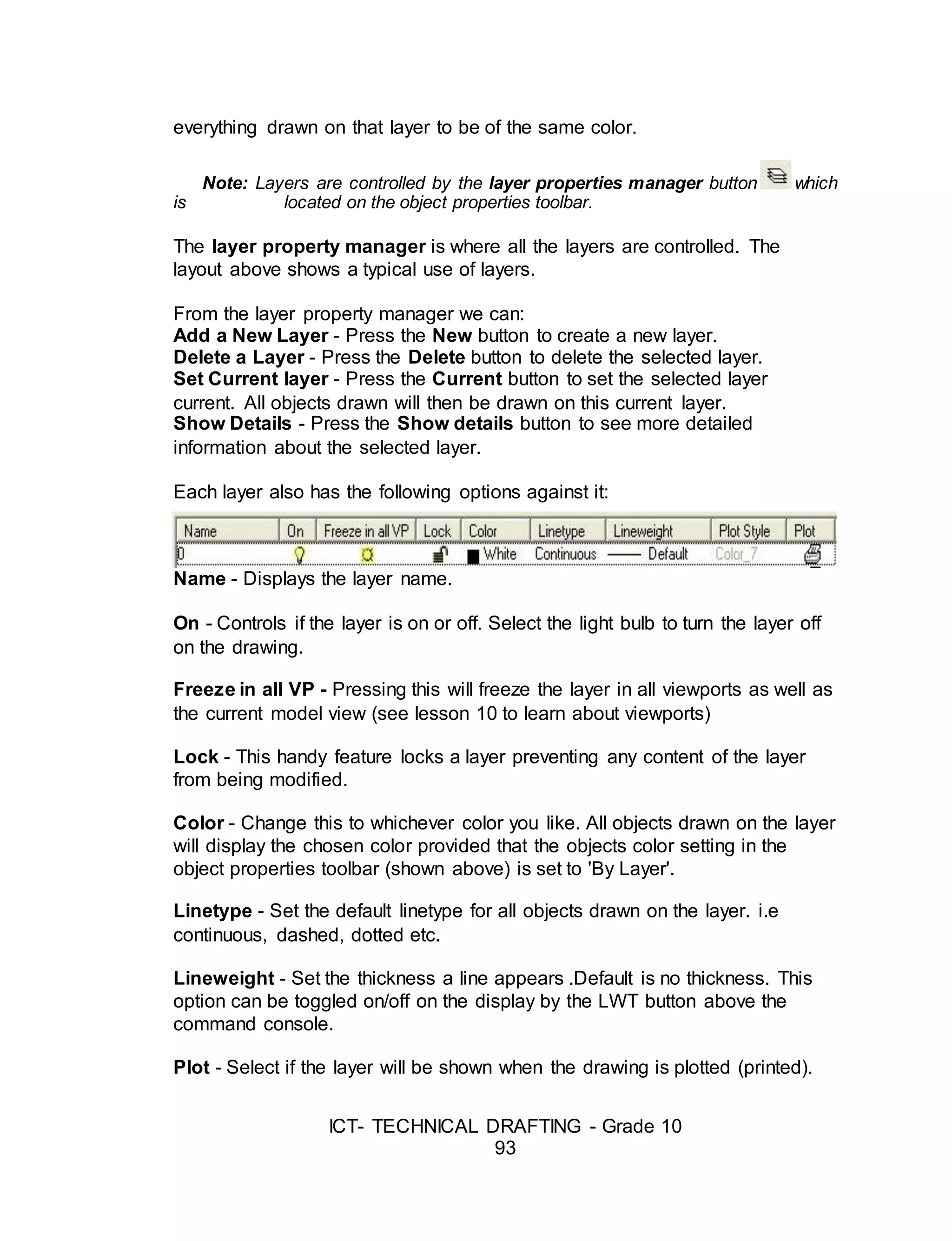
Each layer also has the following options against it:
Name - Displays the layer name.
On - Controls if the layer is on or off. Select the light bulb to turn the layer off
on the drawing.
Freeze in all VP - Pressing this will freeze the layer in all viewports as well as
the current model view (see lesson 10 to learn about viewports)
Lock - This handy feature locks a layer preventing any content of the layer
from being modified.
Color - Change this to whichever color you like. All objects drawn on the layer
will display the chosen color provided that the objects color setting in the
object properties toolbar (shown above) is set to 'By Layer'.
Linetype - Set the default linetype for all objects drawn on the layer. i.e
continuous, dashed, dotted etc.
Lineweight - Set the thickness a line appears .Default is no thickness. This
option can be toggled on/off on the display by the LWT button above the
command console.
Plot - Select if the layer will be shown when the drawing is plotted (printed).
60.
ICT- TECHNICAL DRAFTING- Grade 10
94
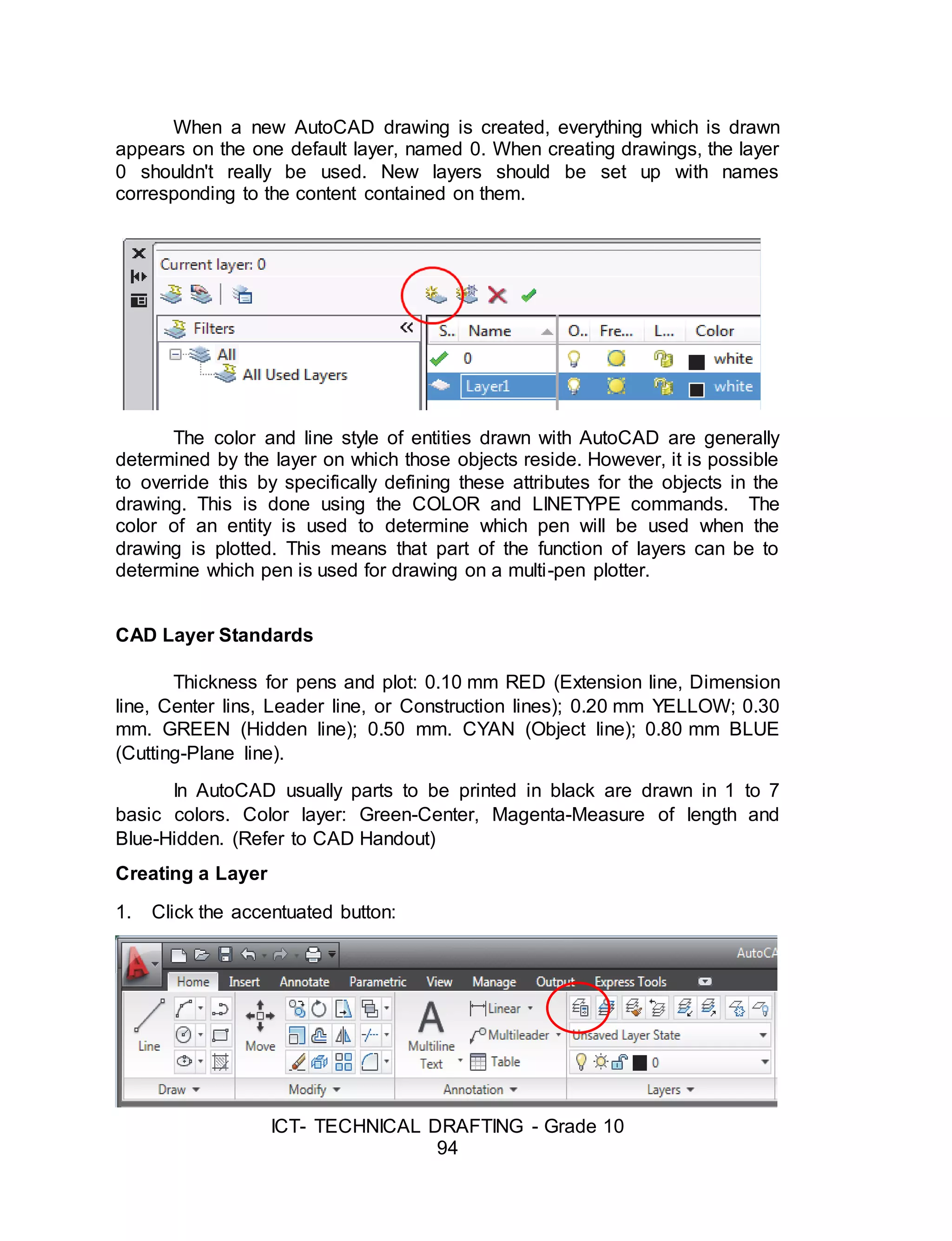
When a new AutoCAD drawing is created, everything which is drawn
appears on the one default layer, named 0. When creating drawings, the layer
0 shouldn't really be used. New layers should be set up with names
corresponding to the content contained on them.
The color and line style of entities drawn with AutoCAD are generally
determined by the layer on which those objects reside. However, it is possible
to override this by specifically defining these attributes for the objects in the
drawing. This is done using the COLOR and LINETYPE commands. The
color of an entity is used to determine which pen will be used when the
drawing is plotted. This means that part of the function of layers can be to
determine which pen is used for drawing on a multi-pen plotter.
CAD Layer Standards
Thickness for pens and plot: 0.10 mm RED (Extension line, Dimension
line, Center lins, Leader line, or Construction lines); 0.20 mm YELLOW; 0.30
mm. GREEN (Hidden line); 0.50 mm. CYAN (Object line); 0.80 mm BLUE
(Cutting-Plane line).
In AutoCAD usually parts to be printed in black are drawn in 1 to 7
basic colors. Color layer: Green-Center, Magenta-Measure of length and
Blue-Hidden. (Refer to CAD Handout)
Creating a Layer
1. Click the accentuated button:
61.
ICT- TECHNICAL DRAFTING- Grade 10
95
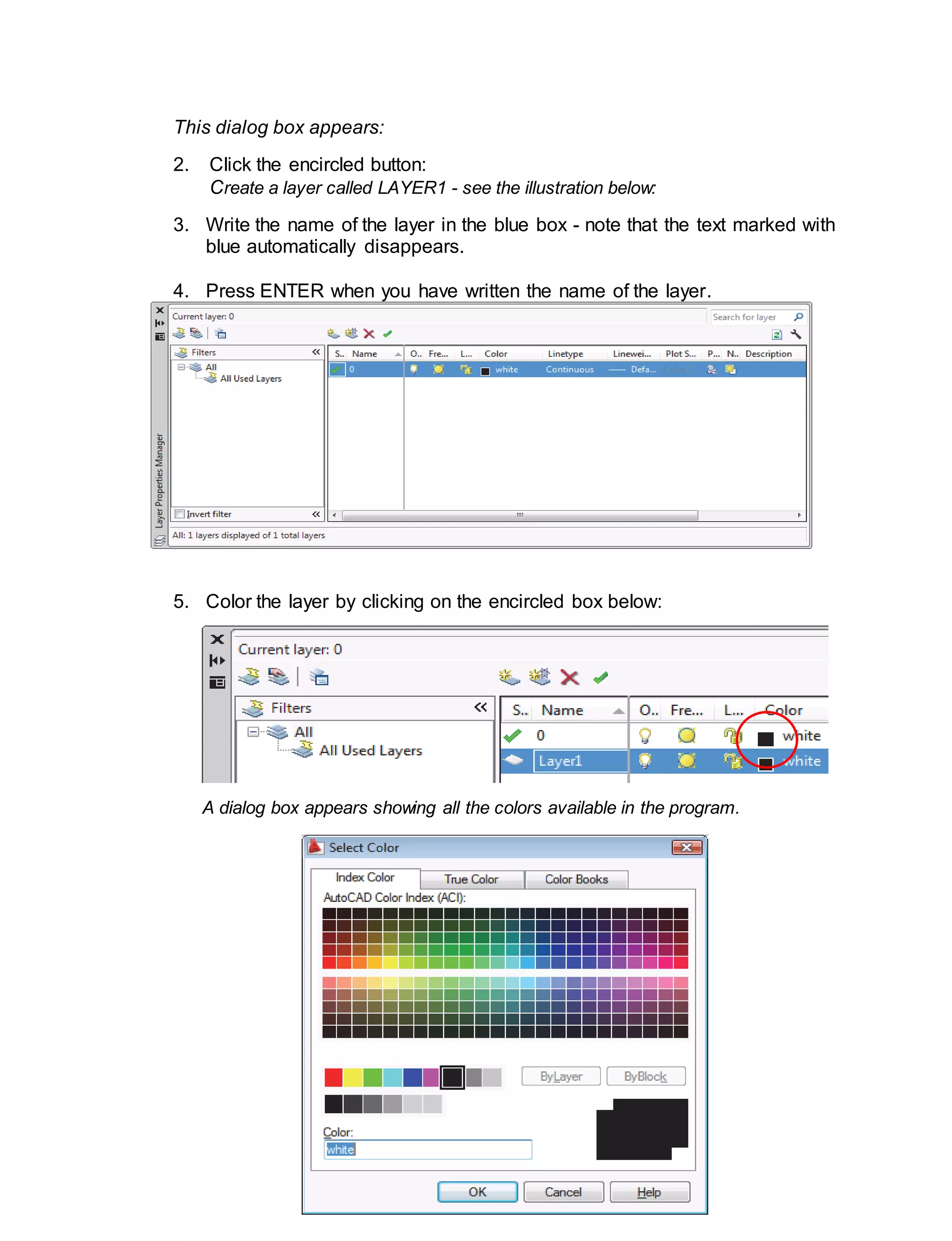
This dialog box appears:
2. Click the encircled button:
Create a layer called LAYER1 - see the illustration below:
3. Write the name of the layer in the blue box - note that the text marked with
blue automatically disappears.
4. Press ENTER when you have written the name of the layer.
5. Color the layer by clicking on the encircled box below:
A dialog box appears showing all the colors available in the program.
62.
ICT- TECHNICAL DRAFTING- Grade 10
96
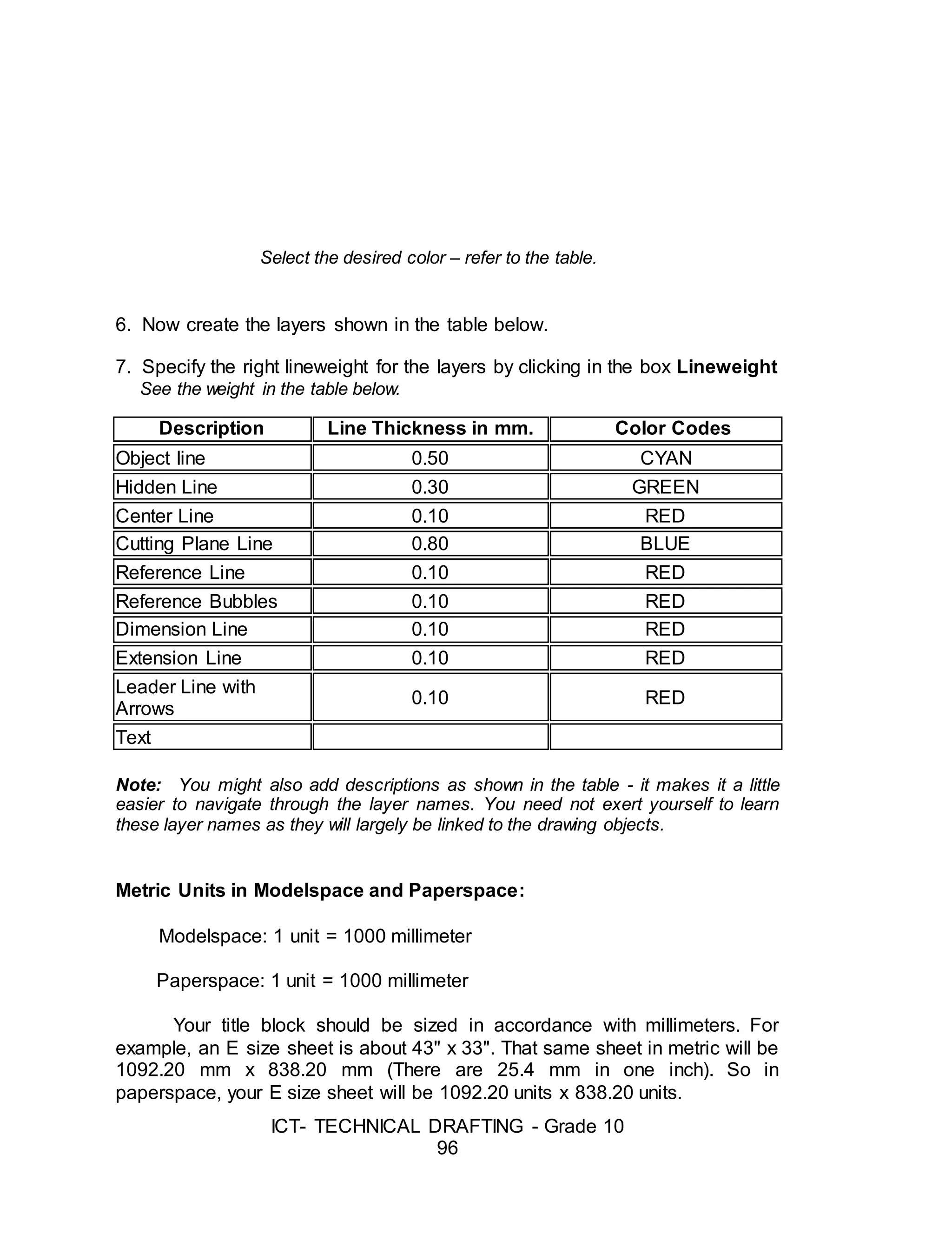
Select the desired color – refer to the table.
6. Now create the layers shown in the table below.
7. Specify the right lineweight for the layers by clicking in the box Lineweight
See the weight in the table below.
Description Line Thickness in mm. Color Codes
Object line 0.50 CYAN
Hidden Line 0.30 GREEN
Center Line 0.10 RED
Cutting Plane Line 0.80 BLUE
Reference Line 0.10 RED
Reference Bubbles 0.10 RED
Dimension Line 0.10 RED
Extension Line 0.10 RED
Leader Line with
Arrows
0.10 RED
Text
Note: You might also add descriptions as shown in the table - it makes it a little
easier to navigate through the layer names. You need not exert yourself to learn
these layer names as they will largely be linked to the drawing objects.
Metric Units in Modelspace and Paperspace:
Modelspace: 1 unit = 1000 millimeter
Paperspace: 1 unit = 1000 millimeter
Your title block should be sized in accordance with millimeters. For
example, an E size sheet is about 43" x 33". That same sheet in metric will be
1092.20 mm x 838.20 mm (There are 25.4 mm in one inch). So in
paperspace, your E size sheet will be 1092.20 units x 838.20 units.
63.
ICT- TECHNICAL DRAFTING- Grade 10
97
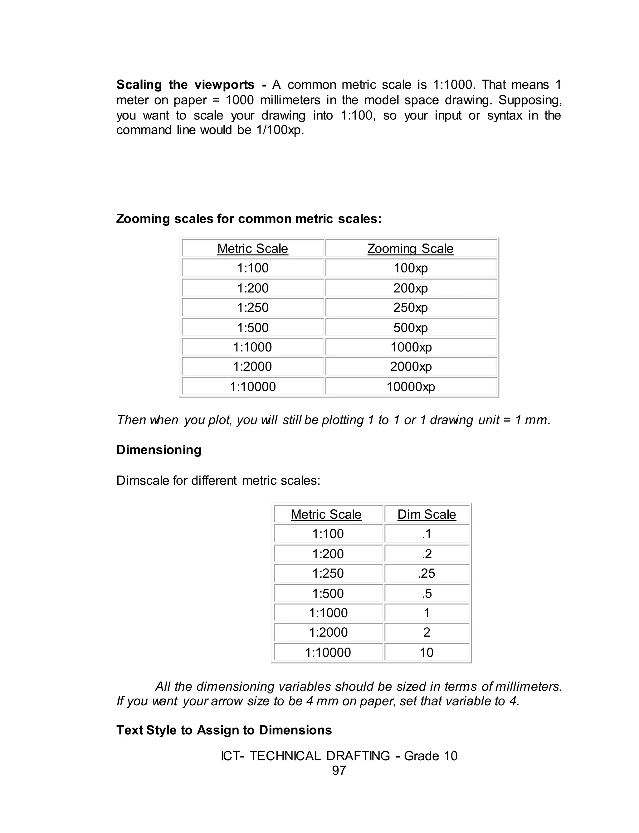
Scaling the viewports - A common metric scale is 1:1000. That means 1
meter on paper = 1000 millimeters in the model space drawing. Supposing,
you want to scale your drawing into 1:100, so your input or syntax in the
command line would be 1/100xp.
Zooming scales for common metric scales:
Metric Scale Zooming Scale
1:100 100xp
1:200 200xp
1:250 250xp
1:500 500xp
1:1000 1000xp
1:2000 2000xp
1:10000 10000xp
Then when you plot, you will still be plotting 1 to 1 or 1 drawing unit = 1 mm.
Dimensioning
Dimscale for different metric scales:
Metric Scale Dim Scale
1:100 .1
1:200 .2
1:250 .25
1:500 .5
1:1000 1
1:2000 2
1:10000 10
All the dimensioning variables should be sized in terms of millimeters.
If you want your arrow size to be 4 mm on paper, set that variable to 4.
Text Style to Assign to Dimensions
64.
ICT- TECHNICAL DRAFTING- Grade 10
98
This text style will not need to be "Annotative," but it will be
compressed horizontally in order to facilitate placing dimension numbers
between extension lines. It will also give dimension text a distinctive look so
they will not be confused with notes.
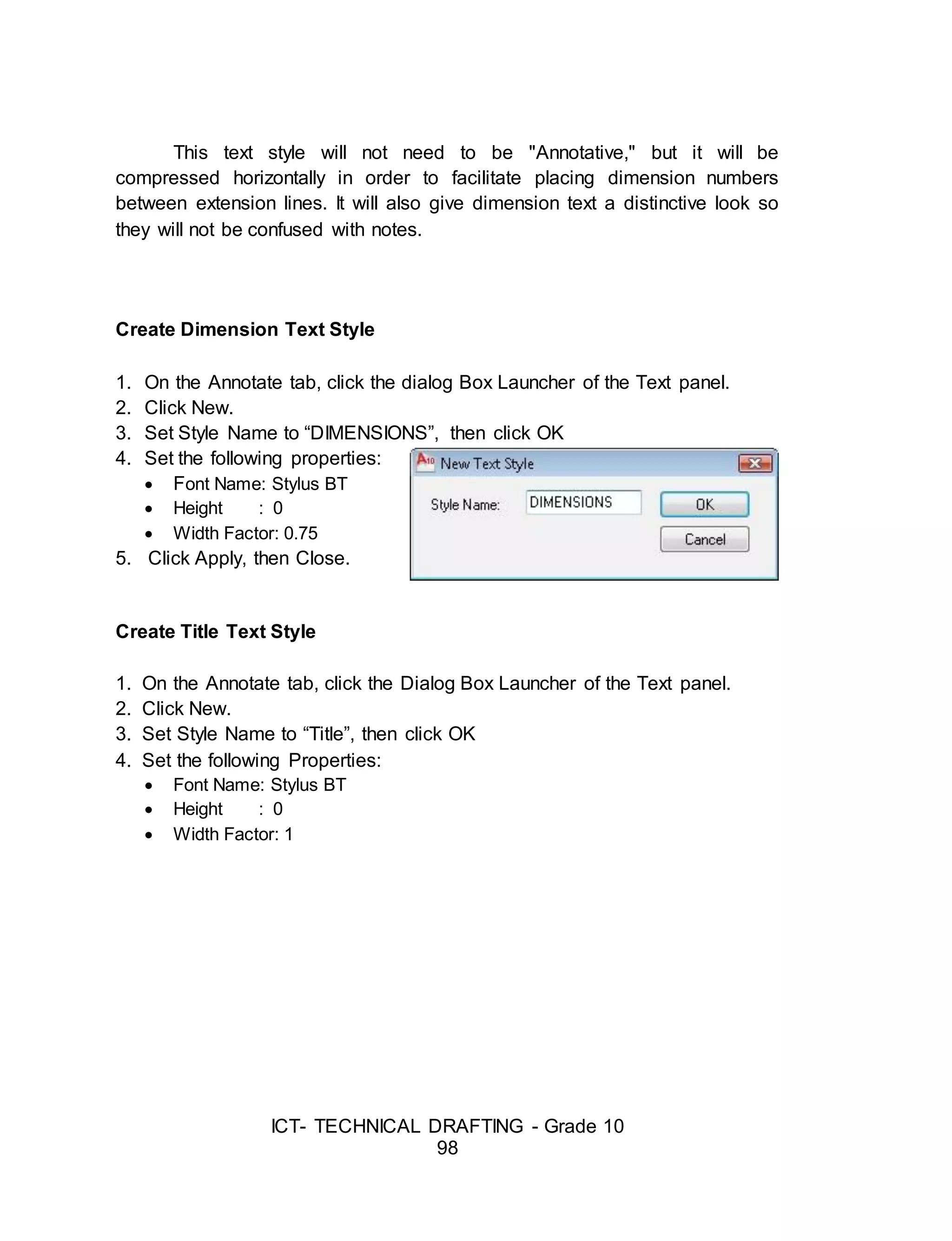
Create Dimension Text Style
1. On the Annotate tab, click the dialog Box Launcher of the Text panel.
2. Click New.
3. Set Style Name to “DIMENSIONS”, then click OK
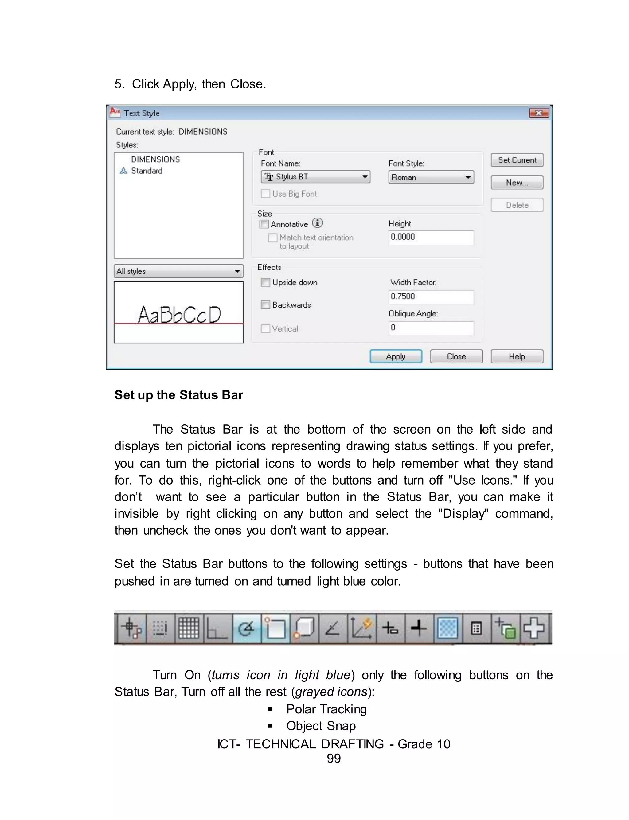
4. Set the following properties:
Font Name: Stylus BT
Height : 0
Width Factor: 0.75
5. Click Apply, then Close.
Create Title Text Style
1. On the Annotate tab, click the Dialog Box Launcher of the Text panel.
2. Click New.
3. Set Style Name to “Title”, then click OK
4. Set the following Properties:
Font Name: Stylus BT
Height : 0
Width Factor: 1
65.
ICT- TECHNICAL DRAFTING- Grade 10
99
5. Click Apply, then Close.
Set up the Status Bar
The Status Bar is at the bottom of the screen on the left side and
displays ten pictorial icons representing drawing status settings. If you prefer,
you can turn the pictorial icons to words to help remember what they stand
for. To do this, right-click one of the buttons and turn off "Use Icons." If you
don’t want to see a particular button in the Status Bar, you can make it
invisible by right clicking on any button and select the "Display" command,
then uncheck the ones you don't want to appear.
Set the Status Bar buttons to the following settings - buttons that have been
pushed in are turned on and turned light blue color.
Turn On (turns icon in light blue) only the following buttons on the
Status Bar, Turn off all the rest (grayed icons):
Polar Tracking
Object Snap
66.
ICT- TECHNICAL DRAFTING- Grade 10
100
Set the following Object Snap functions
Right click on the Object Snap button in the Status Bar and select
“Settings…”
a. Endpoint
b. Midpoint
c. Center
d. Node
e. Quadrant
f. Intersection
g. Perpendicular
h. Nearest
Create a Layout of Border and Title Block
Each “Layout” that you create will carry with it the following elements:
A unique name of each “Layout” as displayed on a tab at the bottom of
the drawing. One or more “Viewports” including a scale for each viewport,
locked or unlocked status for each viewport, and plotting parameters for each
viewport, such as what printer to plot to, paper size, plot scale, drawing
orientation, and plot style table (pen assignments)
Drawing entities you want to have visible and printable in the Layout,
such as drawing title information and a border.
Click on the "Layout1" tab at the bottom of the drawing. This will bring
you into “Paper Space” and allow you to set up viewports and draw a border.
By default you always are drawing in so-called "Model Space," which is where
you should be to draw the 3-dimensional "model" of the building.
67.
ICT- TECHNICAL DRAFTING- Grade 10
101
However, the border of the sheet should be drawn in so-called "Paper
Space." "Paper Space" is a special 2D drawing mode in which you can group
various "views" of your 3D "model" of the building for plotting purposes.
These views are typically plan, elevation, section, and perspective and
are created in "viewports" drawn in the Paper Space Layout. Since the model
of the building is the only drawing, when the model is changed, the plans,
elevations, and sections are automatically changed in their viewports. The
great advantage of working this way is that you can visualize the building or
space as it will actually exist in three dimensions.
Standard Printing Specifications
Given this ease of changing sizes, it is of course common to copy or
print a given document on different sizes of paper, Text made with technical
pen of 5 mm in height has a stroke or line thickness of 0.5 mm, and so
requires a brown-nibbed 0.5 mm technical pen. If this text were drawn on an
ISO-sized document (e.g. A0), and the document were reproduced at half its
original size (A1), the text would be rendered 3.5 mm high with a stroke
thickness of 0.35 mm - the yellow-nib size.
Thus, changes to reductions or enlargements can be made easily as
everything is in proportion. This standard ensures that drawings can always
be legible even after microfilming, photocopying, and faxing. Below is the
European standard paper sizes and their relationship:
68.
ICT- TECHNICAL DRAFTING- Grade 10
102
Suggested Activity 2: Create Dimension Style
DDIM Dialog Box
Sample European
Standard Paper Size
69.
ICT- TECHNICAL DRAFTING- Grade 10
103
In this lesson, you will create a new Dimension Style and use it in a
drawing. From there, you should try different styles and get familiar with the
options. Most companies these days will have a standard style (or set of
styles) to use on drawings, but this is a very important tool to know if you want
to turn out professional looking drawings.
1. Start but invoking the DDIM command and press the NEW button to
open the small dialog for entering the name of the style you are
creating. In this example use the name "DIMSTYLE 1".
2. New Dimstyle
Make sure that "Start with" has "Standard" as its setting. Press the
Continue Button when everything is set. This will open the dialog box for
settings, so just press OK to close it for now.
70.
ICT- TECHNICAL DRAFTING- Grade 10
104
3. Back at the "Dimension Style Manager" dialog box, you will see that
the new style you created is listed at the top (left side). To modify it,
select the name, then press the modify button. The dialog box opens
and click on the second tab Symbols and Arrows.
As a general rule, we recommend not to change much on this tab. Set
as defaults, the dimensions are sized proportionately, if you change the
setting on one parameter, your dimension can look 'off-balance'.
For example, you could end up with huge arrows and small text. For
the purposes of this lesson, the only thing that will change on this tab is the
arrowheads. Select something other than the standard. You'll also see that
you can set the colors, but just like regular objects, it is best to leave them set
to "Bylayer" - and make sure you have a separate layer for all dimensions.
71.
ICT- TECHNICAL DRAFTING- Grade 10
105
4. Go to the third tab Text.
5. Start up the Text Styles dialog box by pressing the button with the ...
next to the text name. Create a new textstyle using RomanS and a
width of 0.8 and call it "DIMTEXT".
6. Close the Text Styles dialog box. Select DIMTEXT as your text for
dimensions as shown.
The great thing about this dialog box is that it shows you a preview of what
your changes will do the final dimension in the top right window. In the bottom right,
select ISO as the Text Alignment option. Try some other changes to see their effects
in the preview, then end with the settings as shown below:
7. Click on the next tab to continue.
8. Click on the next tab (Primary Units) to continue.
72.
ICT- TECHNICAL DRAFTING- Grade 10
106
9. In the Primary Units, you find some of the more common parameters
that need to be changed. Precision is very important. 3 Decimal places is
usually enough.
73.
ICT- TECHNICAL DRAFTING- Grade 10
107
Suggested Activity 3 – Creating Text Styles
Directions: Create the following Text Styles.
Multiline Text:
1. Type MT command and press enter key.
2. On the workspace, pick the first point and the second point that will serve
as the text box.
3. Set the height of the text…say 200
4. Type the desired text… say plan
5. Close text editor
6. Apply zoom extends command by pressing Z (enter key) E (enter key)
Create a Layout of Border and Title Block
Elements of the Layout of Border and Title Blocks
A unique name
1. Tab at the bottom of the drawing. One or more Viewports including
a scale for each viewport, locked or unlocked status for each
viewport, and plotting parameters for each viewport, such as what
printer to plot to, paper size, plot scale, drawing orientation, and
plot style table (pen assignments)
Title informational border
74.
ICT- TECHNICAL DRAFTING- Grade 10
108
2. Drawing entities you want to have visible and printable in the
Layout, such as drawing title information and a border.
Paper Space and Model Space
3. Click on the "Layout1" tab at the bottom of the drawing. This will
bring you into “Paper Space” and allow you to set up viewports and
draw a border. By default you always are drawing in so-called
"Model Space," which is where you should be to draw the 3-
dimensional "model" of the building.
3D-Dimensional Model
4. However, the border of the sheet should be drawn in so-called
"Paper Space." "Paper Space" is a special 2D drawing mode in
which you can group various "views" of your 3D "model" of the
building for plotting purposes.
Viewpoints
5. These views are typically plan, elevation, section, and perspective
and are created in "viewports" drawn in the Paper Space Layout.
Since the model of the building is the only drawing, when the model
is changed, the plans, elevations, and sections are automatically
changed in their viewports. The great advantage of working this
way is that you can visualize the building or space as it will actually
exist in three dimensions.
SUMMATIVE ASSESSMENT
Suggested Actvity 4
75.
ICT- TECHNICAL DRAFTING- Grade 10
109
Directions: Using the Floor Plan in Appendix B, page 113 - 114 draft the
same floor plan using autoCAD. Your finished working drawing will be
assessed using the suggested rubric in Appendix A, page 112.
Suggested Activity 5
Directions: Apply the basic and modifying commands in creating a Layout of
Border Line and Title Block.
Requirements for the Layout Plan
1. Paper Size: A4
2. Boarder Line: 15.00 mm. around
3. Title Block:
3.1 Height = 30.00 mm.
A. 30.00 mm.
B. 90.00 mm.
C. 70.00 mm.
D. 100. 00 mm.
Suggested Commands:
REC, OFFSET, LINE, TRIM, OSNAP, & ORTHO
Post-Assessment:
A
B C D
76.
ICT- TECHNICAL DRAFTING- Grade 10
110
Answer the post-assessment below to determine whether there is
significant increase in your understanding of preparing drawings using
computer-aided designing.
Directions: Choose the letter of the correct answer. Write your answer in the
space provided before each number.
_____ 1. This is commonly known as the physical equipment that makes up
the computer system.
A. Hardware B. Mouse C. Printer D. Software
_____ 2. It is the brain of the computer where most of the “computing” takes
place.
A. CPU B. Disk Drive C. Hardware D. Monitor
_____ 3. This is the main purpose of the left mouse button.
A. To execute a command C. To serve as abort button
B. To repeat the last command D. To serve as pick button
_____ 4. The set of programs, procedures, and related documentation
associated with a computer system.
A. Disk Drive C. Printer
B. Hardware D. Software
_____ 5. Of the following software, which is not an application software?
A. Adobe Photoshop C. Flash
B. AutoCAD D. Windows 8
_____ 6. Which of the following options is not type of workspaces?
A. 2D Drafting & Annotation C. 3D Modeling
B. My workspace D. AutoCAD Classic
_____ 7. Which of the function keys can be used for activating the Osnap
Mode?
A. F3 B. F5 C. F9 D. F8
_____ 8. Which command is used to change the size of an existing objects?
A. Move B. Rotate C. Scale D. Zoom
_____ 9. Which command can be used to create a new text style (TS) and
modify the existing ones?
77.
ICT- TECHNICAL DRAFTING- Grade 10
111
A. Dtext B. Mtext C. Text D. Style
_____ 10. Which of the keyboard keys must be pressed to execute a
command
or to accept an Auto CAD default?
A. F2 and Enter C. Enter and Esc
B. Enter and Space bar D. Esc and Space bar
_____ 11. With a hot grip you can perform these editing tasks
A. Move B. Offset C. Rotate D. Scale
_____ 12. Which of the following is important in setting the chamfer
command?
A. Angle point 1 and 2 C. Distance 1 and 2
B. Base point 1 and 2 D. Radius 1 and 2
_____ 13. What is the default file extension of an AutoCAD drawing?
A. Dwg B. Dwf C. Dws D. Dwt
_____ 14. If you need the text to be reversed, you mirror the text, then you
need to set:
A. MIRRTEXT to 0 C. TEXTMIRR to 0
B. MIRRTEXT to 1 D. TEXTMIRR to 1
_____ 15. Which keystrokes will UNDO a command?
A. Alt+U B. Alt+Z C. Control+U D. Control+Z
_____ 16. Which of the following dimensioning commands is evident in the
drawing?
A. Dimaligned C. Dimlinear
B. Dimangular D. Qleader
_____ 17. Which of the following is necessary in setting the fillet command?
A. Angle B. Base point C. Distance D. Radius
_____ 18. Which of the following can be joined using Join command
A. Arc B. Circle C. Construction line D. Ray
_____ 19. The following are some of the properties and settings that you can
78.
ICT- TECHNICAL DRAFTING- Grade 10
112
save in a layout, except.
A. Plot scale C. Paper size
B. Line weight D. Drawing orientation
_____ 20. What command is used to specify settings in dimension style
manager?
A. Ddim B. Dimspec C. Dimalt D. Dimsize
Appendix A.
Assessment Tool: Product & Performance Rubric
Name: ____________________________________ Date: __________
Year & Section: _____________________________________________
Criteria 5 points 3 points 1 point
Proficiency Perform the task
with competence
and exceptional
performance
Perform the task
with competence
and with
standard
performance
Perform the task
with competence
but below
standard
performance
Layout/Proportion All drawings
were drawn
proportionately
Layout was good
but 1-2 drawing
were out of
More than 2
drawings were
drawn out of
79.
ICT- TECHNICAL DRAFTING- Grade 10
113
and was layout
properly
proportion proportion and
improperly layout
Completeness Perform all the
steps in
sequence
Perform the task
with at least 1-3
steps are not
met
Perform the task
with 3 or more
steps are not
met
Time
Management
Finish the task
ahead of the
given time and
date
Finish the task
on the given time
and date
Unable to finish
the task on the
given time and
date
Rating Scale:
Points Earned Numerical Rating Descriptive Rating
17 – 20 91 – 100 Outstanding
13 – 16 86 – 90 Very Good
9 – 12 81 – 85 Good
5 – 8 76 – 80 Fair
1 - 4 71 - 75 Needs Improvement
Teacher’s Comments:
Teacher’s Signature: _______________ Date: _____________
Appendix B.
FLOOR PLAN
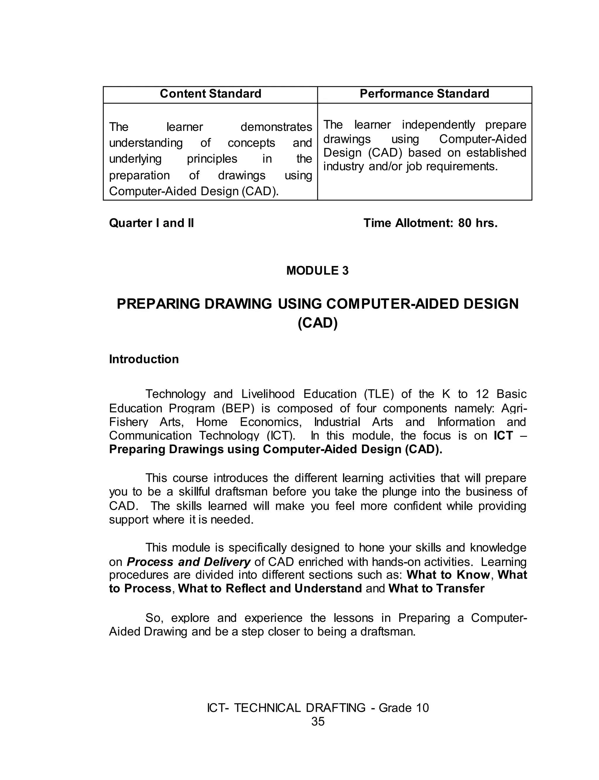
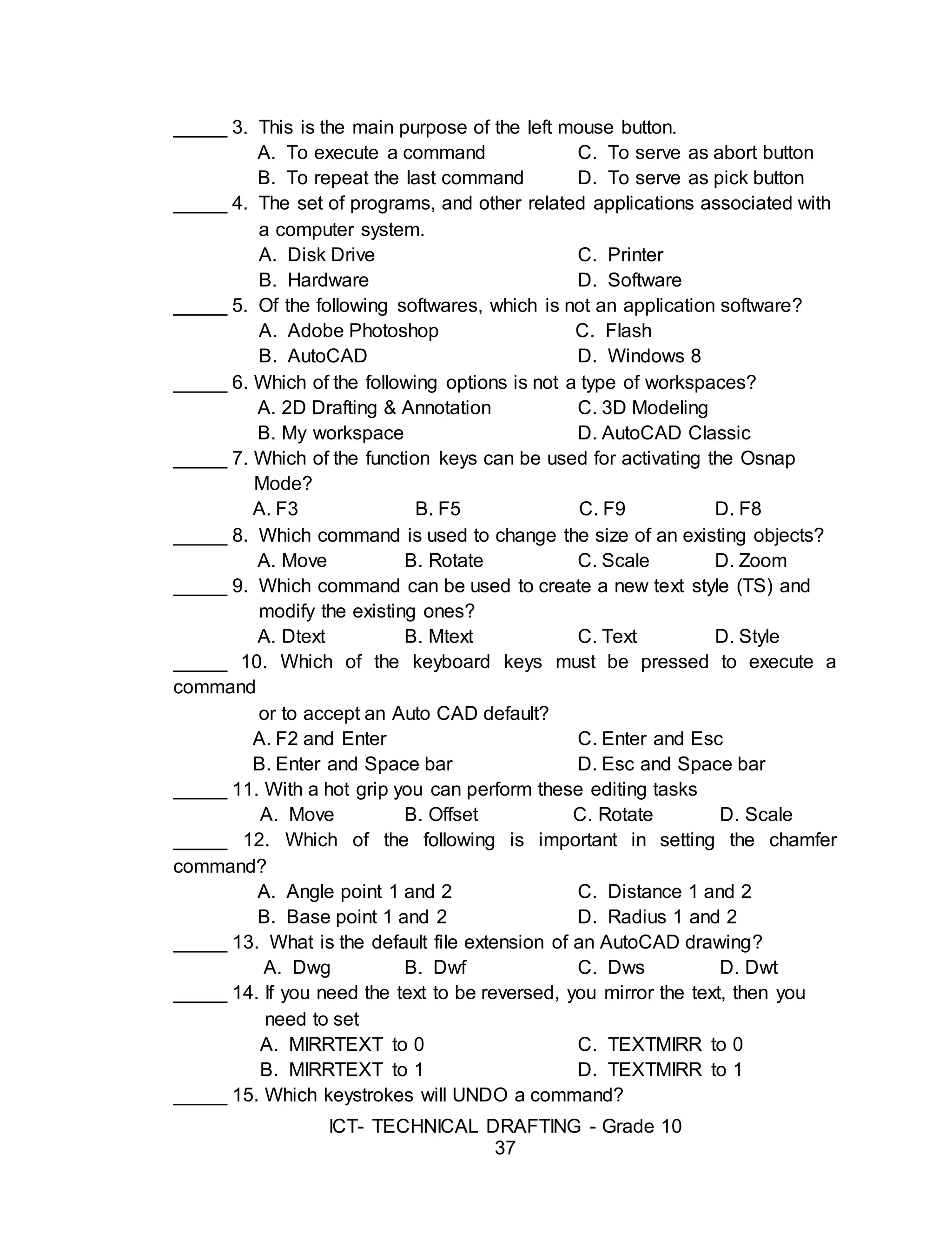
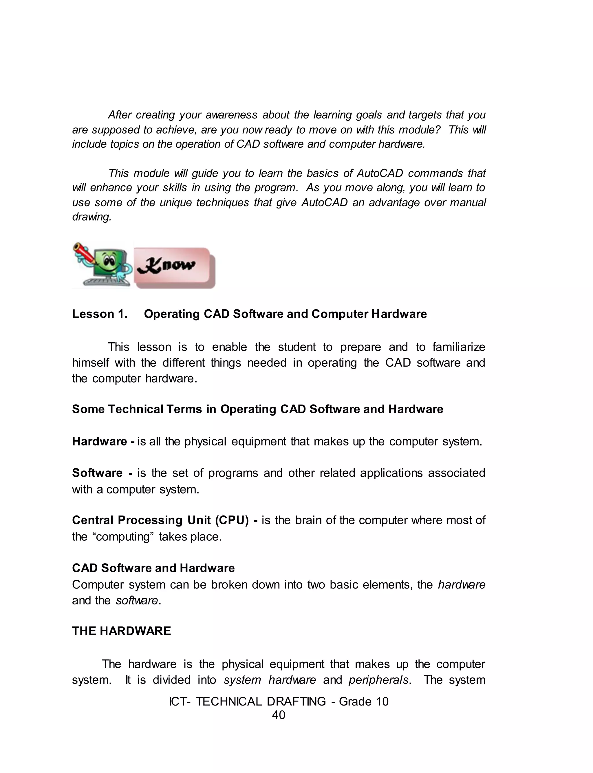
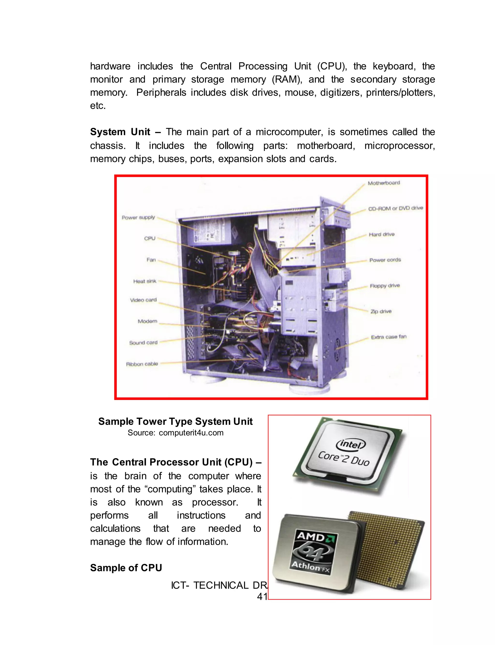
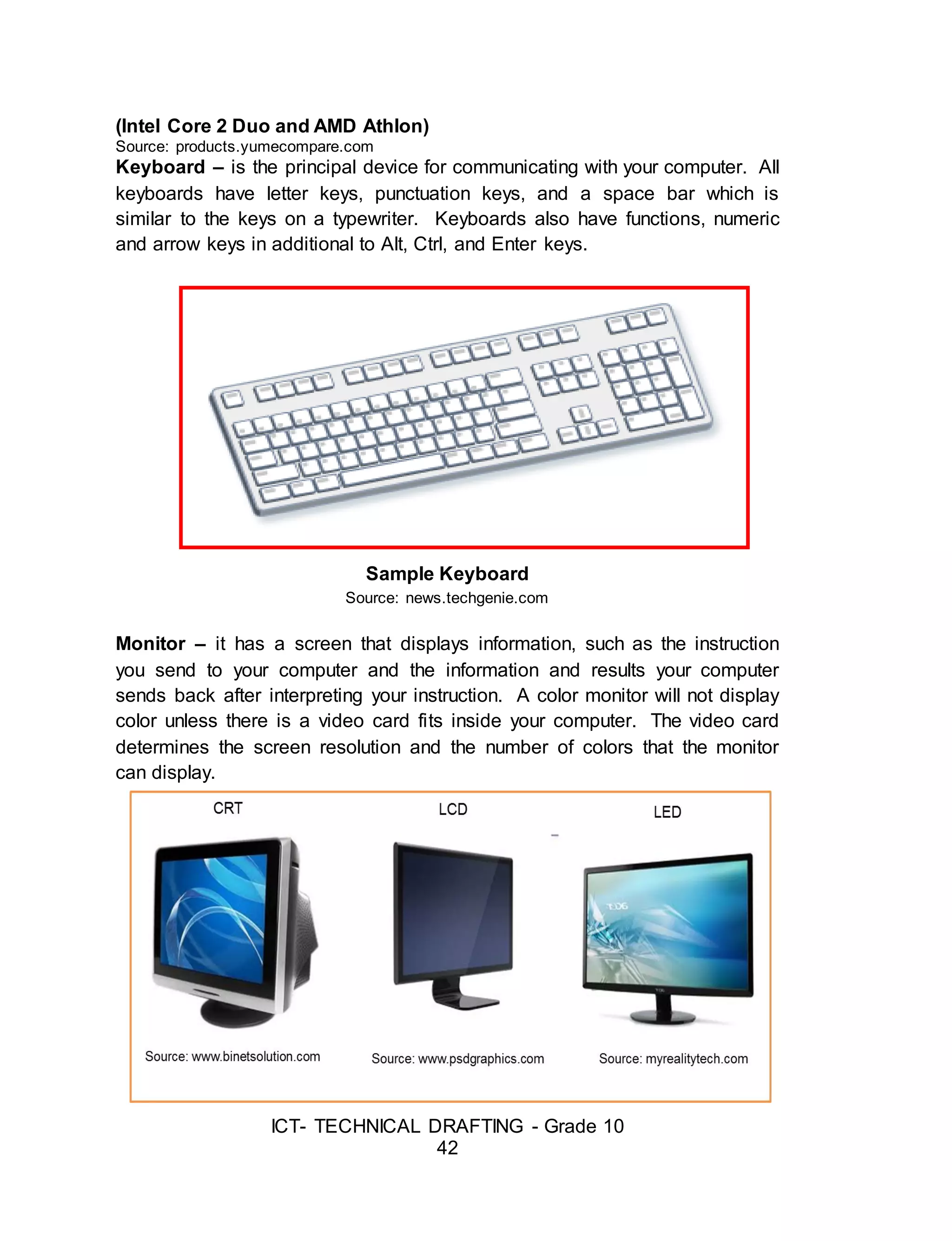
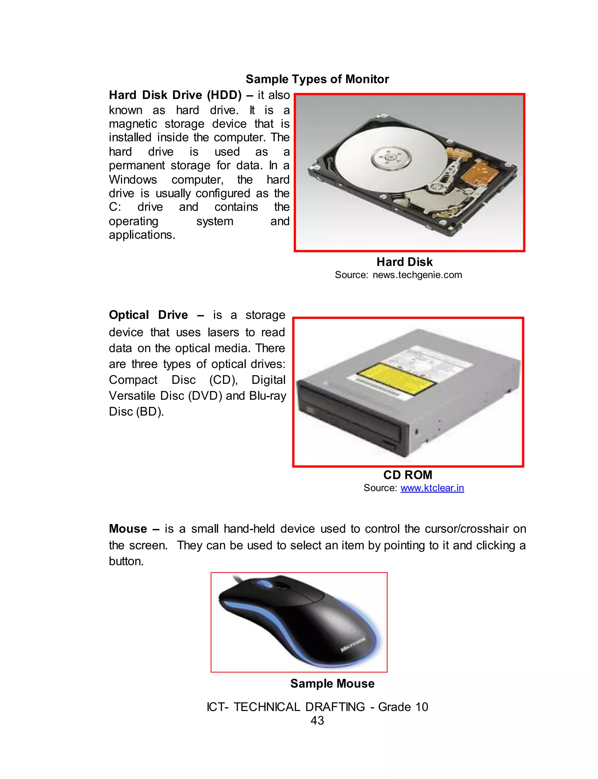
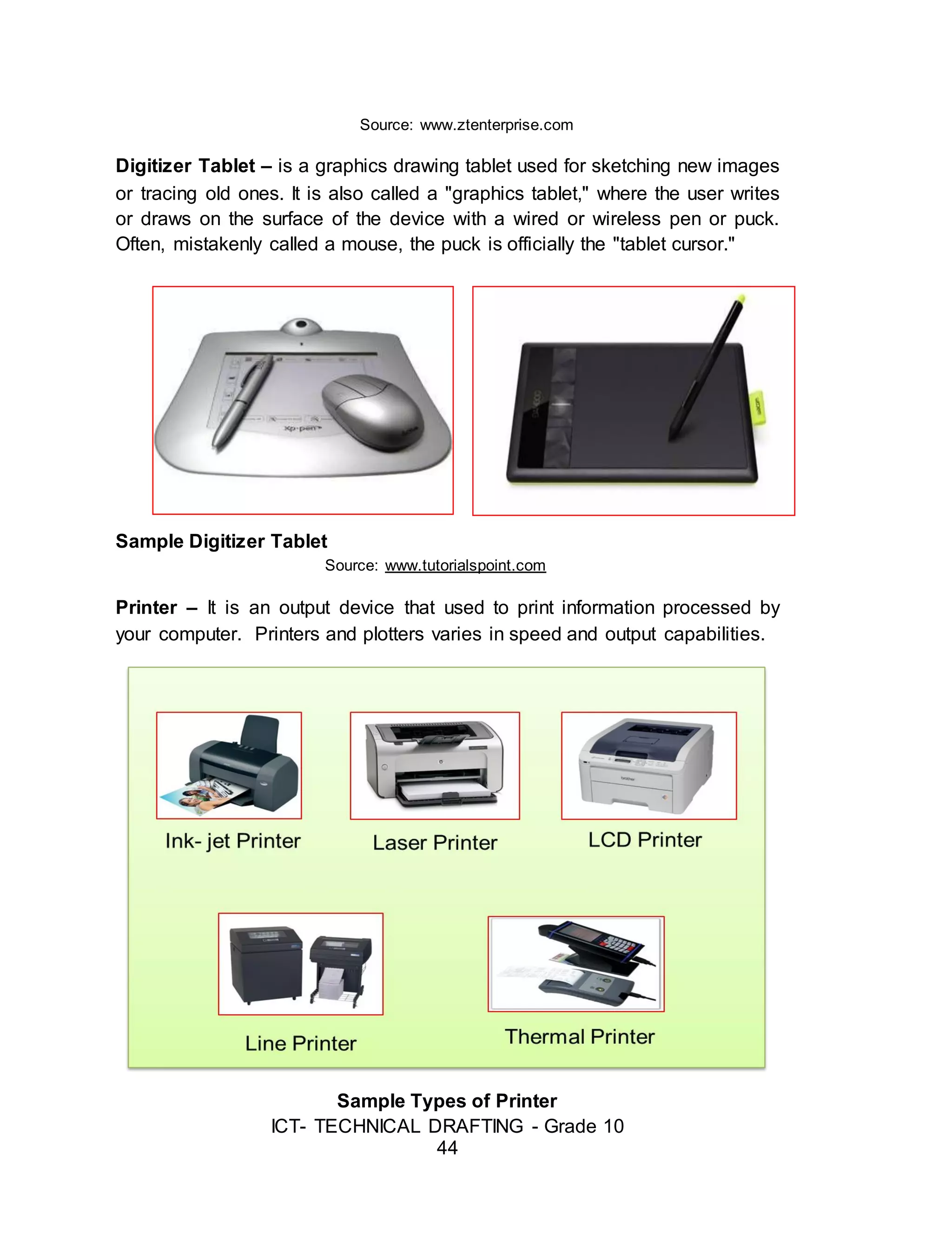
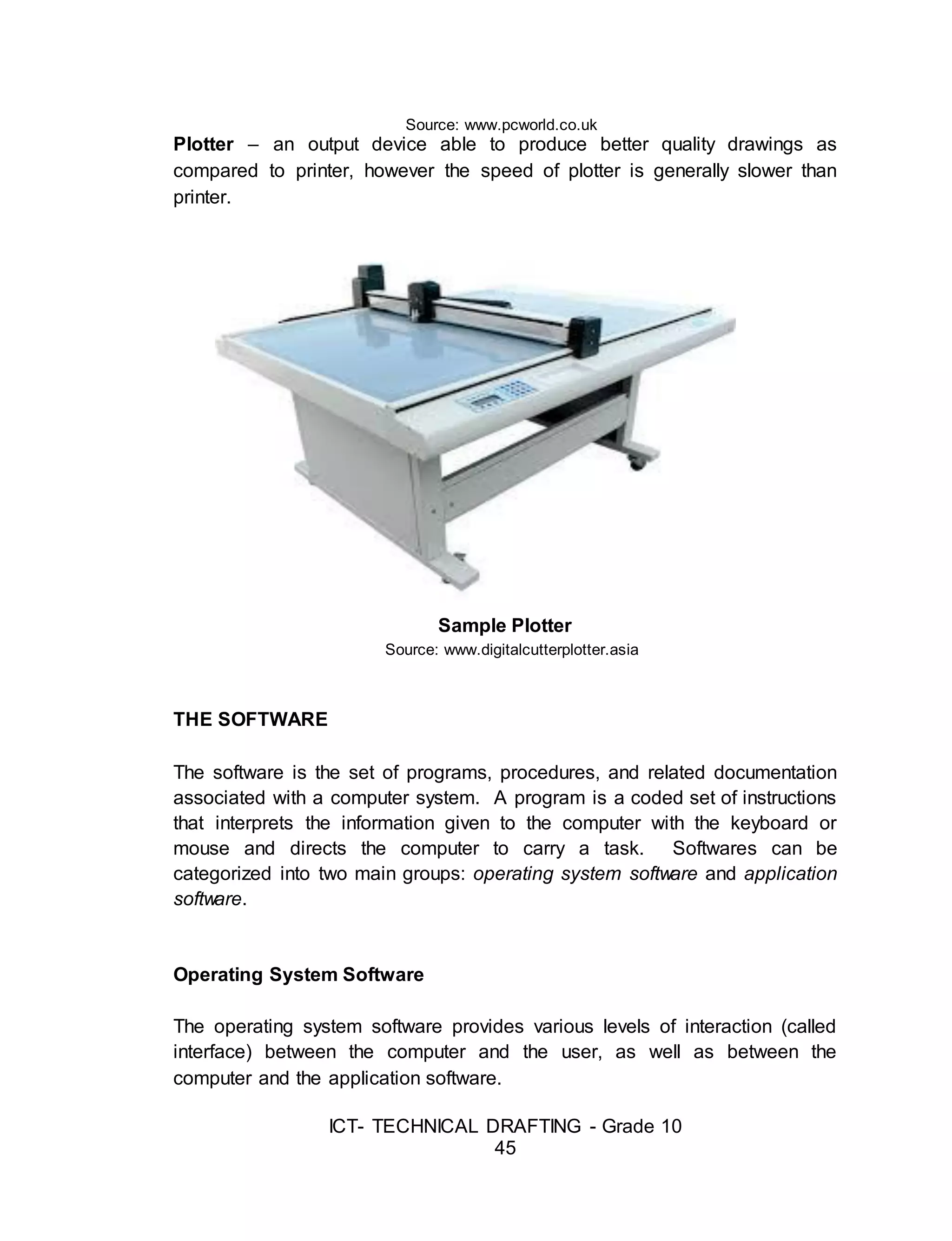

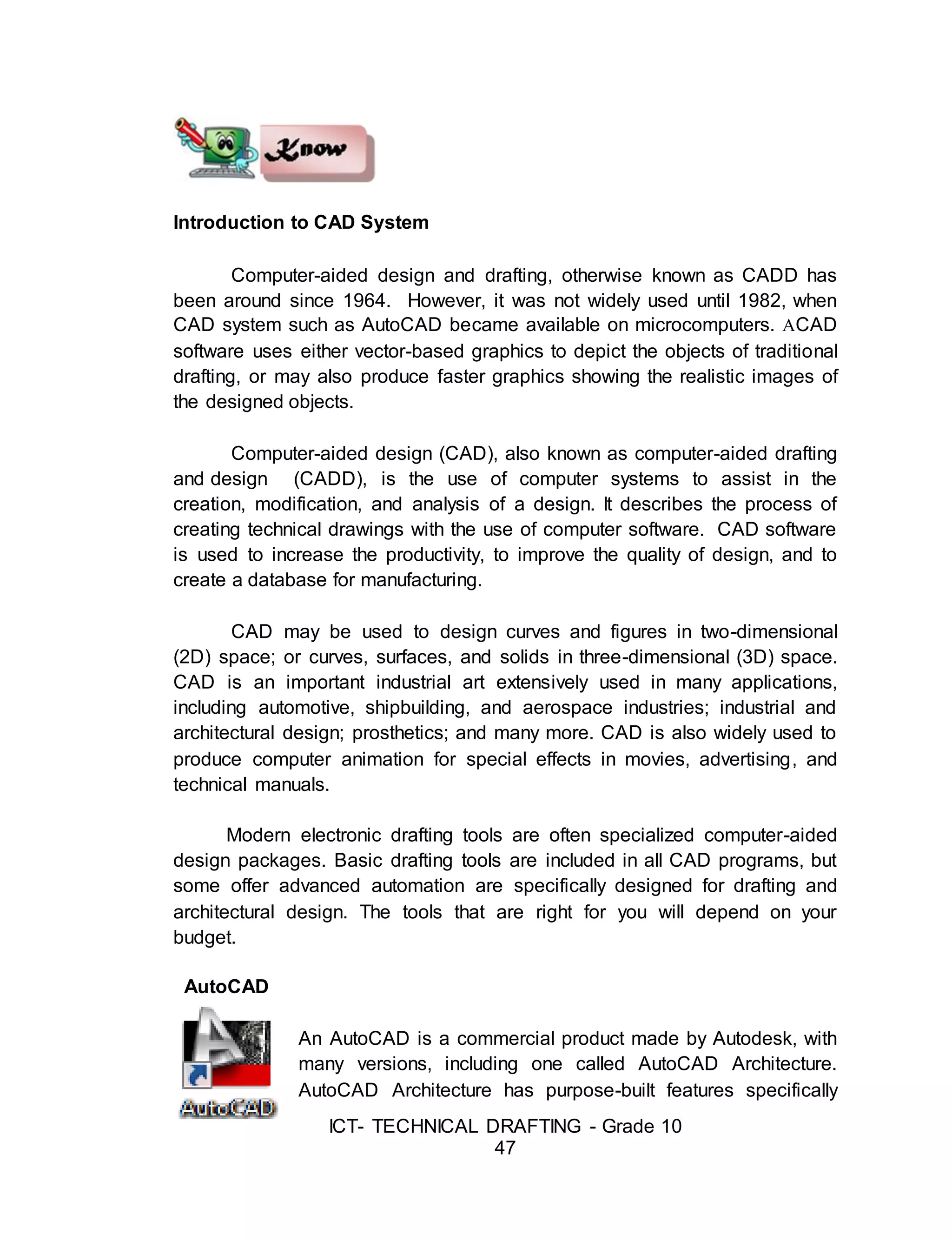
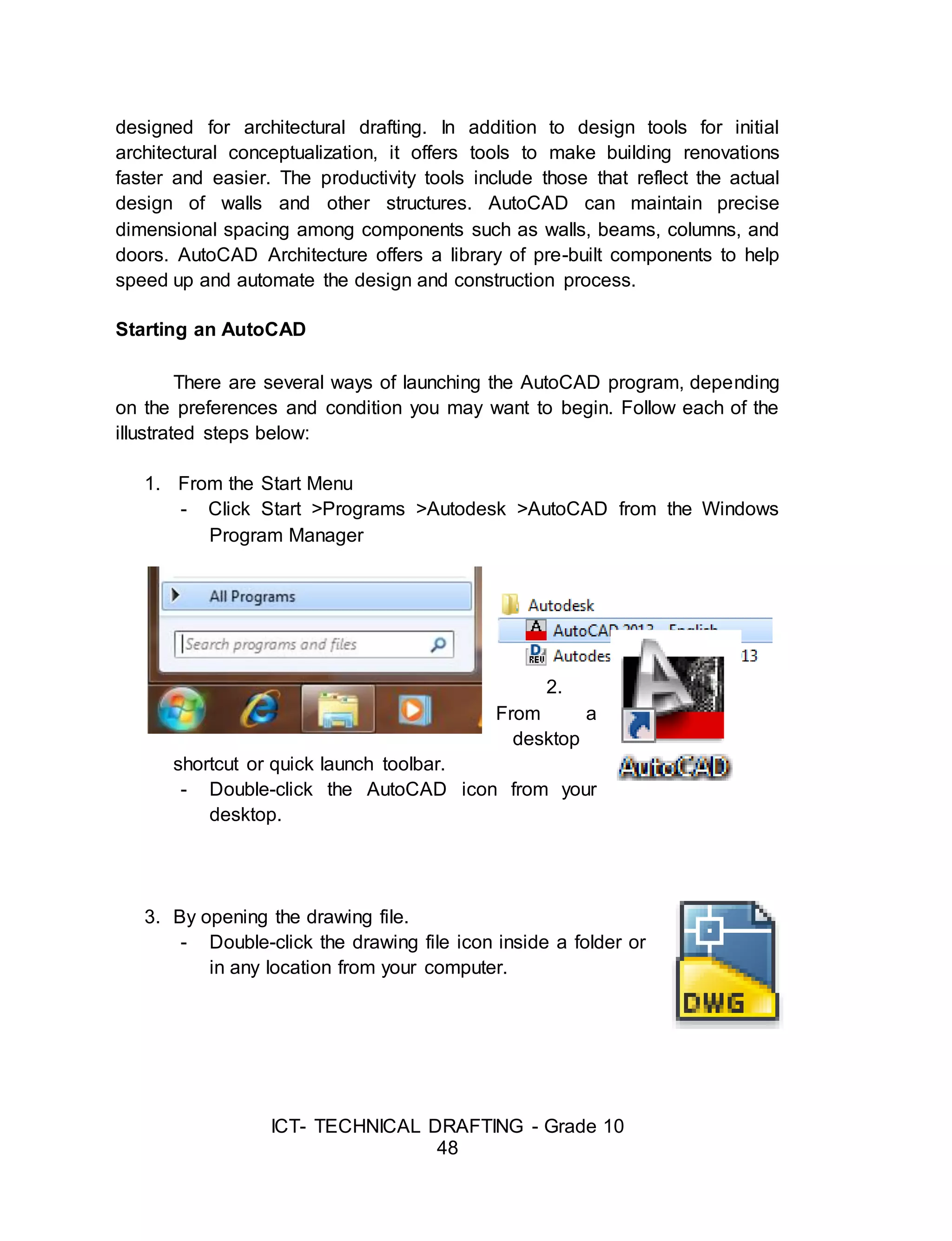
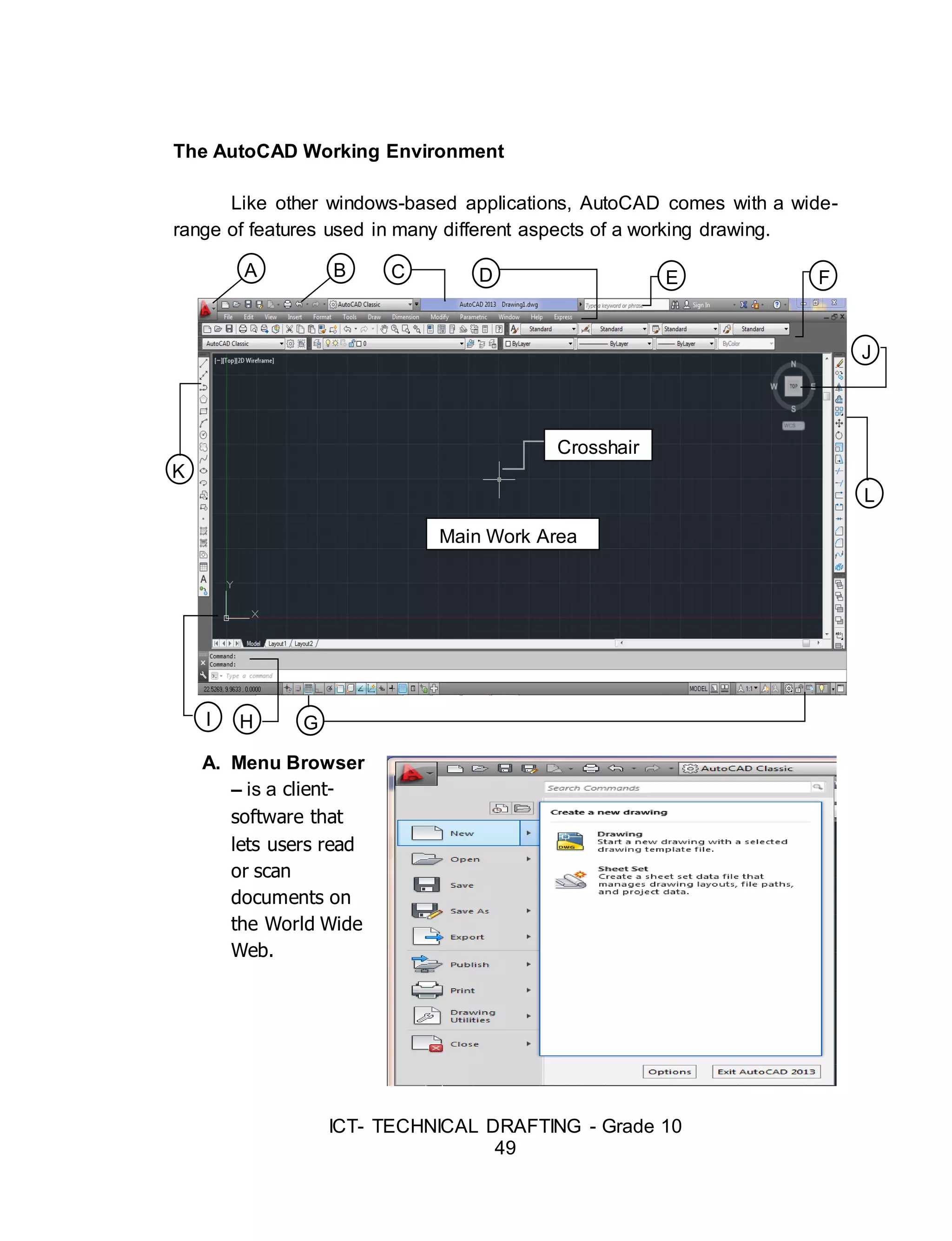
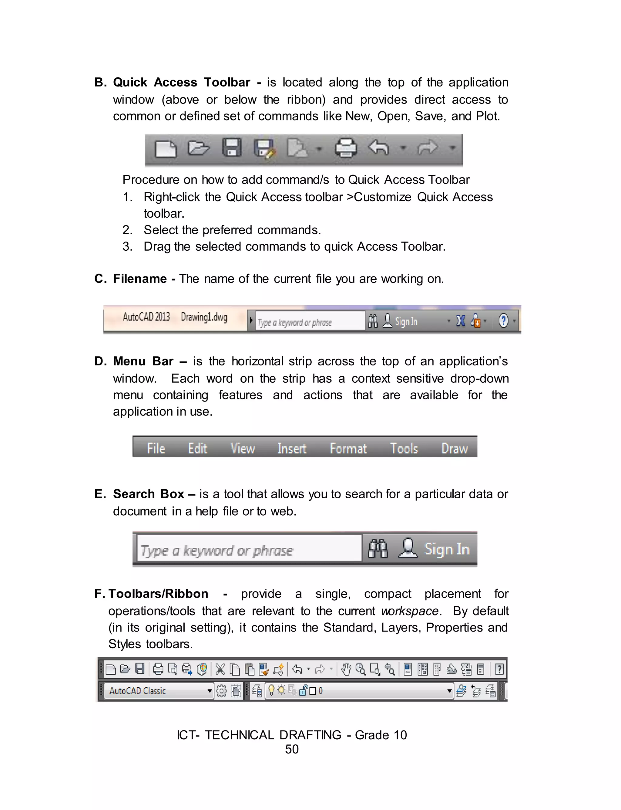
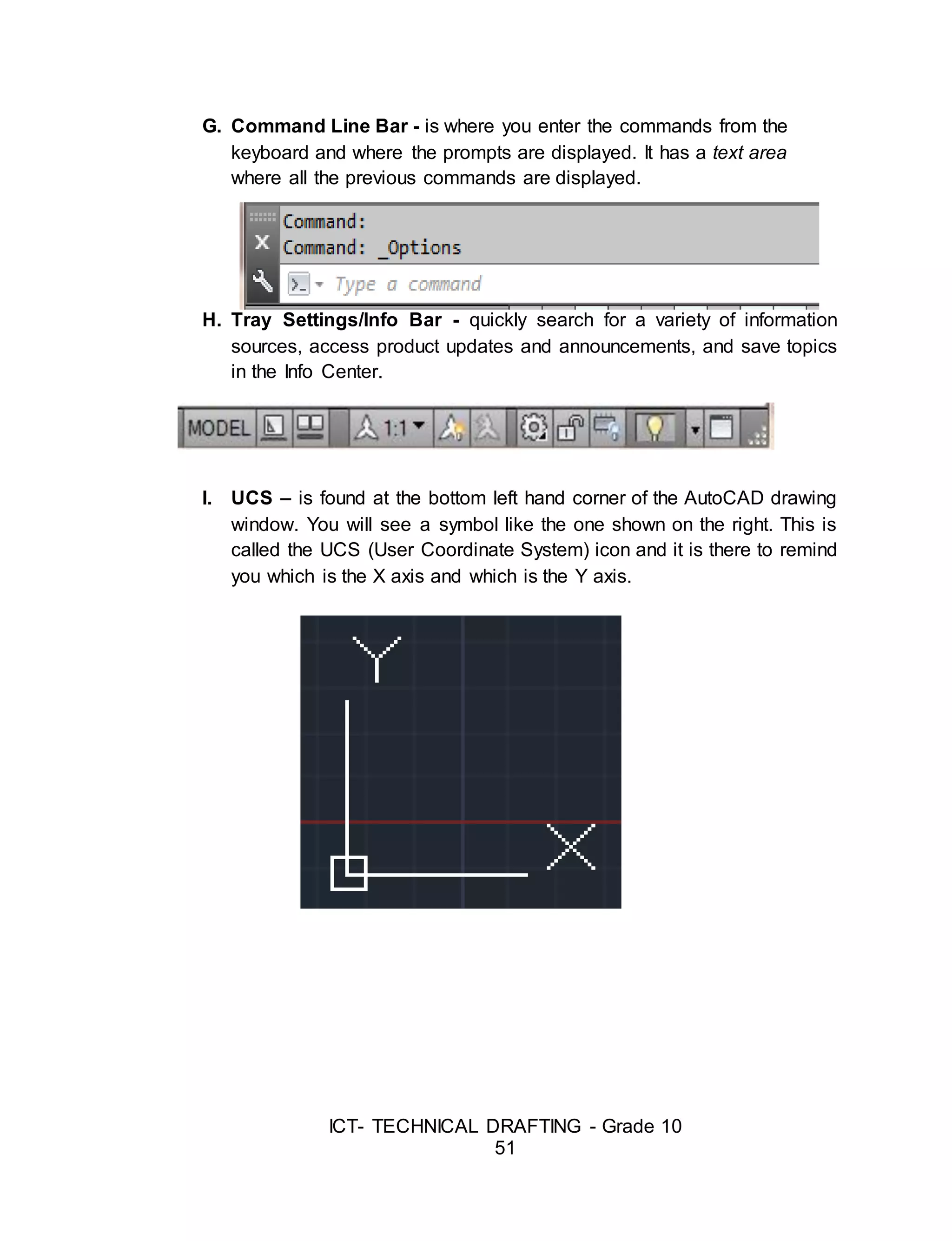
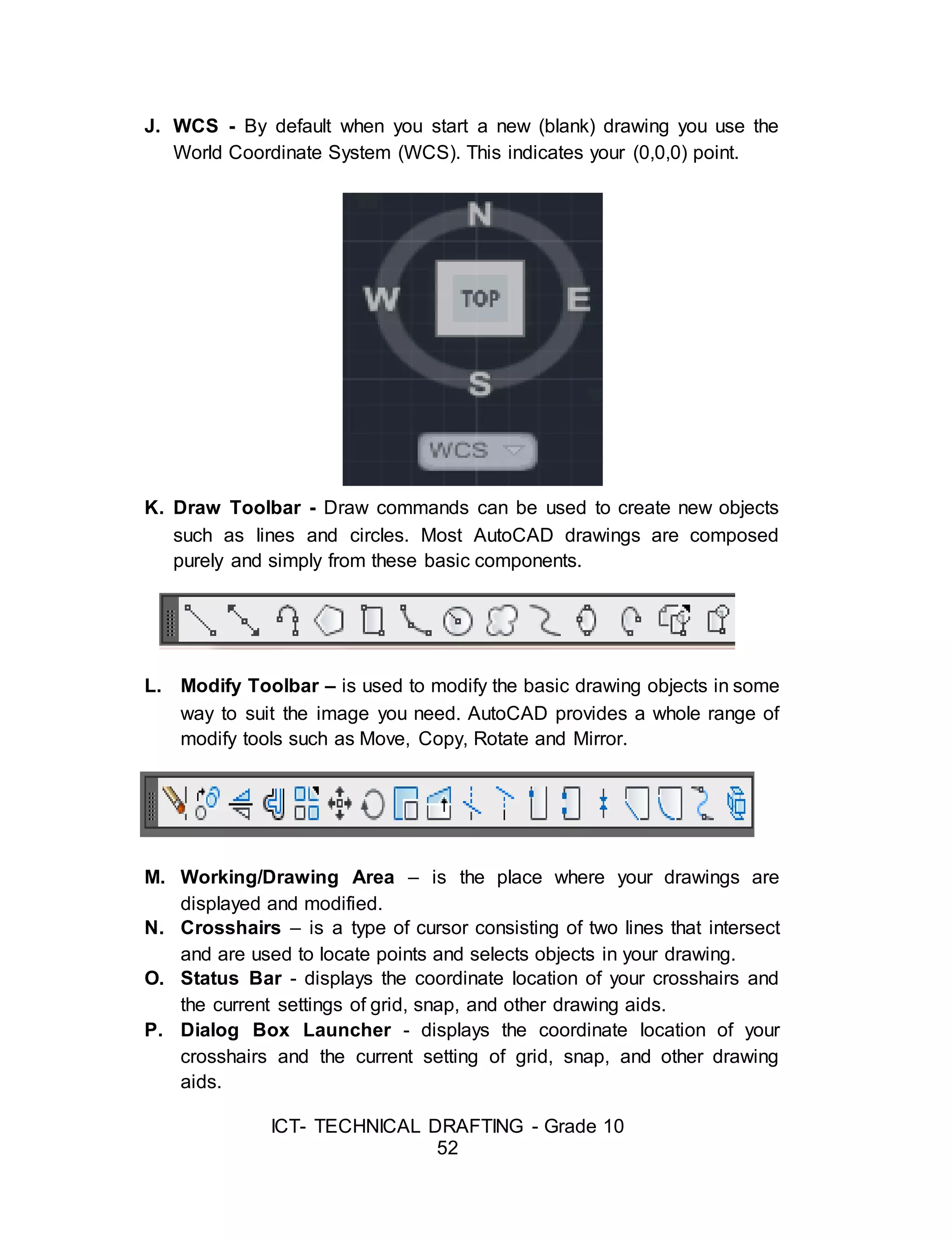
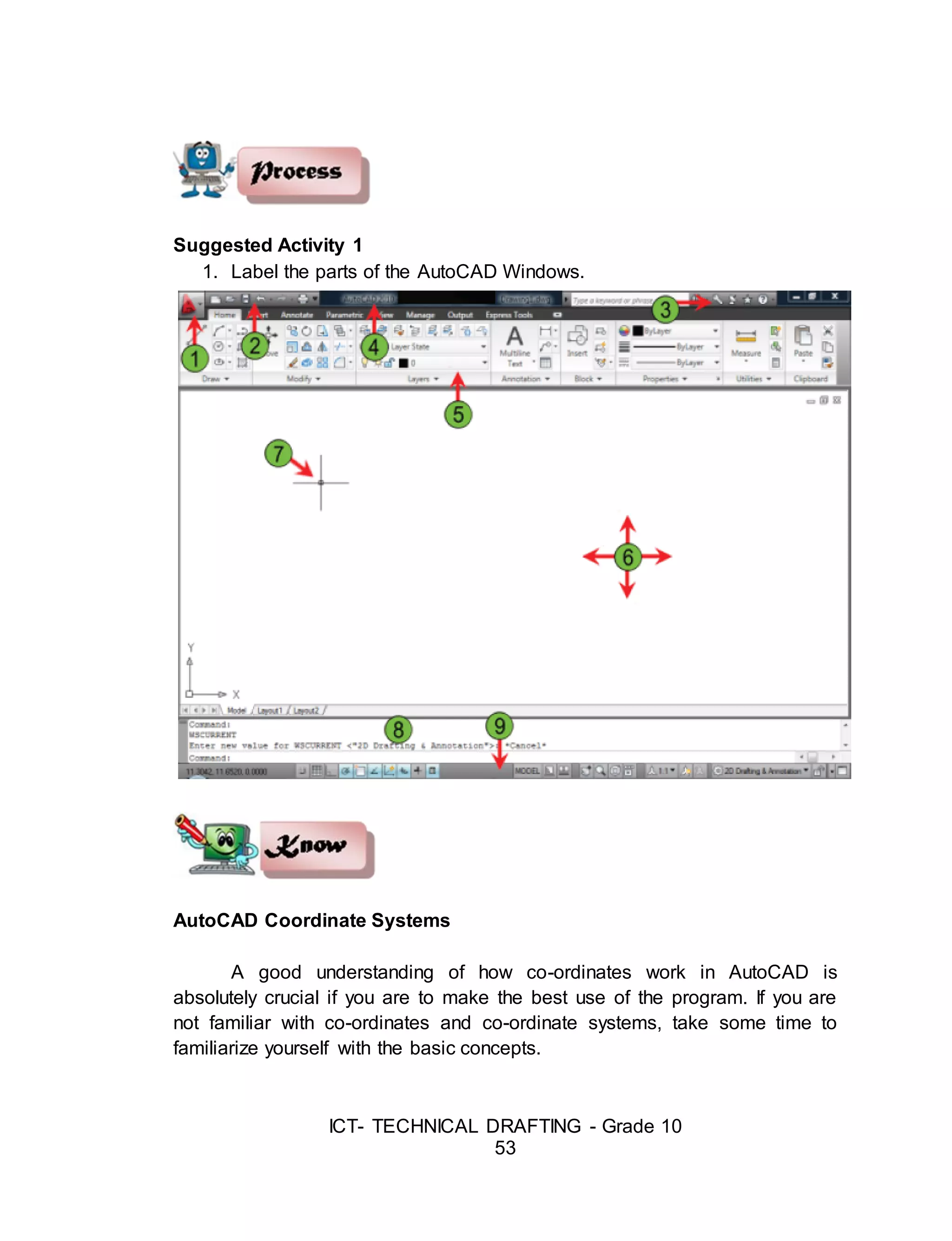
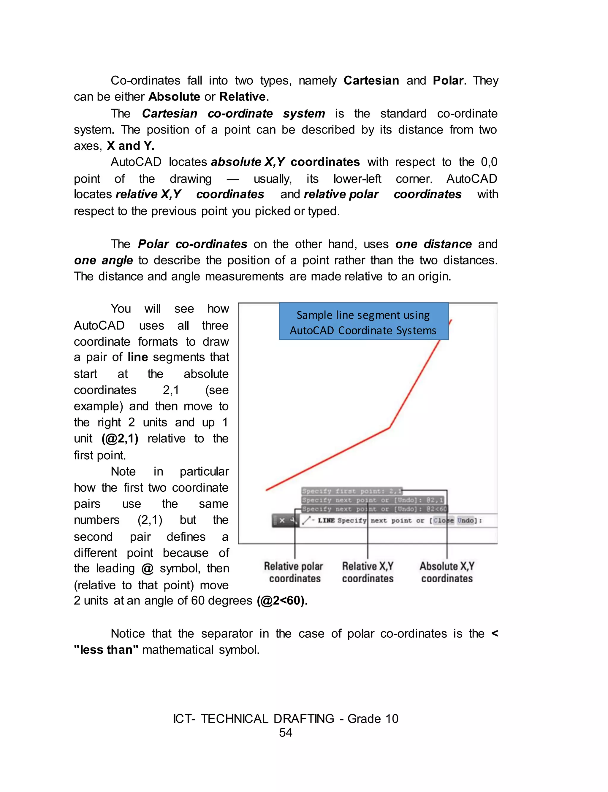

![ICT- TECHNICAL DRAFTING - Grade 10
56
Specify next point or [Undo]: (pick P2)
Specify next point or [Undo]: [press esc or enter]
The Polyline Command
The Polyline or Pline command is similar to
the line command except that the resulting object may be composed of a
number of segments which form a single object. In addition to the two ends a
polyline is said to have vertices (singular vertex) where intermediate line
segments join. In practice the Polyline command works in the same way as
the Line command allowing you to pick as many points as you like. As with
the Line command, you also have the option to automatically close a polyline
end to end. To do this, type C to use the close option instead of hitting. Follow
the command sequence below to see how this works.
Command: PLINE or PL[enter]
Specify start point: (pick P1)
Current line-width is 0.0000
Specify next point or [Arc/Half width/Length/Undo/Width]: (pick P2)
Specify next point or [Arc/Close/Half width/Length/Undo/Width]: (pick P3)
Specify next point or [Arc/Close/Half width/Length/Undo/Width]: (pick P4)
Specify next point or [Arc/Close/Half width/Length/Undo/Width]: (pick P5)
Specify next point or [Arc/Close/Half width/Length/Undo/Width]: (or C to
close)
The Rectangle Command
The Rectangle command is used to draw a rectangle whose sides are
vertical and horizontal. The position and size of the rectangle are defined by
picking two diagonal corners. The rectangle isn't really an AutoCAD object at
all. It is, in fact, just a closed polyline which is automatically drawn for you.
Command: RECTANG or REC[enter]
Specify first corner point or
[Chamfer/Elevation/Fillet/
Thickness/Width]: (pick P1)](https://image.slidesharecdn.com/b-tdgrade10lmmodule3preparingcomputer-aideddrawing-170626104020/75/Technical-Drafting-Module-3-22-2048.jpg)
![ICT- TECHNICAL DRAFTING - Grade 10
57
Specify other corner point or [Dimensions]: (pick P2)
The Rectangle command also has a number of options. Width works in
the same way as for the Polyline command. The Chamfer and Fillet options
have the same effect as the Chamfer and Fillet commands.
The Polygon Command
The Polygon command can be used to draw any regular polygon from
3 sides up to 1024 sides. This command requires four inputs from the user,
the number of sides, a pick point for the center of the polygon, whether you
want the polygon inscribed or circumscribed and then a pick point which
determines both the radius of this imaginary circle and the orientation of the
polygon.
Command: POLYGON or POL[enter]
Enter number of sides <4>: 5
Specify center of polygon or [Edge]: (pick P1 or type E to define by edge
length)
Enter an option [Inscribed in circle/Circumscribed about circle] <I>:
(To accept the inscribed default or type C for circumscribed)
Specify radius of circle: (pick P2 or enter exact radius)
The Donut Command
This command draws a solid donut shape, actually it's just a closed
polyline consisting of two arc segments which have been given a width.
AutoCAD asks you to define the inside diameter i.e. the diameter of the hole](https://image.slidesharecdn.com/b-tdgrade10lmmodule3preparingcomputer-aideddrawing-170626104020/75/Technical-Drafting-Module-3-23-2048.jpg)
![ICT- TECHNICAL DRAFTING - Grade 10
58
and then the outside diameter of the donut. The donut is then drawn in outline
and you are asked to pick the center point in order to position the donut. You
can continue picking center points to draw more donuts or you can hit to end
the command.
Command: DONUT or DO[enter]
Specify inside diameter of donut <0.5000>:
(pick any two points to define a diameter or enter the exact length)
Specify outside diameter of donut <1.0000>: (pick any two points to define a
diameter or enter the exact length)
Specify center of donut or <exit>: (pick P1)
Specify center of donut or <exit>: [Enter]
The Circle Command
The Circle command is used to draw circles. There are a number of
ways you can define the circle. The default method is to pick the center point
and then to either pick a second point on the circumference of the circle or
enter the circle radius at the keyboard.
Command: CIRCLE or C[enter]
Specify center point for circle or [3P/2P/Ttr (tan tan radius)]: (pick P1)
Specify radius of circle or [Diameter] <50.0195>: (pick P2 or enter the exact
radius)
As you can see from the command prompt above the default options
are always indicated in triangular brackets like so <Default> and command
options appear within square brackets like so [Option]. Each option is
separated by a forward slash like this /.
The Arc command
The Arc command allows you to draw an arc
of a circle. There are numerous ways to define an](https://image.slidesharecdn.com/b-tdgrade10lmmodule3preparingcomputer-aideddrawing-170626104020/75/Technical-Drafting-Module-3-24-2048.jpg)
![ICT- TECHNICAL DRAFTING - Grade 10
59
arc, the default method uses three pick points - a start point, a second point
and an end point. Using this method, the drawn arc will start at the first pick
point, pass through the second point and end at the third point.
Command: ARC or A[enter]
Specify start point of arc or [Center]: (pick P1)
Specify second point of arc or [Center/End]: (pick P2)
Specify end point of arc: (pick P3)
Note: It is also possible to create an arc by trimming a circle object.
The Spline Command
The Spline command creates a type of spline known as a non-uniform
rational B-spline, NURBS for short. A spline is a smooth curve that is fitted
along a number of control points. The Fit Tolerance option can be used to
control how closely the spline conforms to the control points. A low tolerance
value causes the spline to form close to the control points.
A tolerance of 0 (zero) forces the spline to pass through the control
points. The illustration on the right shows the effect of different tolerance
values on a spline that is defined using the same four control points, P1, P2,
P3 and P4. Splines can be edited after they have been created using the
SPLINEDIT command, Modify Object Spline from the pull-down menu. Using
this command, you can change the tolerance, add more control points move
control points and close splines, among other things. However, if you just
want to move spline control points, it
is best to use grips.
Command: SPLINE or SPL[enter]
Specify first point or [Object]: (Pick P1)
Specify next point: (Pick P2)
Specify next point or [Close/Fit
tolerance] <start tangent>: (Pick P3)
Specify next point or [Close/Fit
tolerance] <start tangent>: (Pick P4)](https://image.slidesharecdn.com/b-tdgrade10lmmodule3preparingcomputer-aideddrawing-170626104020/75/Technical-Drafting-Module-3-25-2048.jpg)
![ICT- TECHNICAL DRAFTING - Grade 10
60
Specify next point or [Close/Fit tolerance] <start tangent>:
Specify start tangent: (pick a point)
Specify end tangent: (pick a point)
Sample Spline Output
The Ellipse Command
The Ellipse command gives you a number of different creation options
whereas the default option has only three options, that is it picks that is, it
picks the two end points of an axis and then a third point to define the
eccentricity of the ellipse. After you have mastered the default option, try out
the ellipse command.
Command: ELLIPSE or EL[enter]
Specify axis endpoint of ellipse or [Arc/Center]: (pick P1)
Specify other endpoint of axis: (pick P2)
Specify distance to other axis or
[Rotation]: (pick P3)
The ellipse command can also be used to draw isometric circles.
Object Selection
Before you start to use the AutoCAD Modify commands, you need to
know something about selecting objects. All of the Modify commands require](https://image.slidesharecdn.com/b-tdgrade10lmmodule3preparingcomputer-aideddrawing-170626104020/75/Technical-Drafting-Module-3-26-2048.jpg)
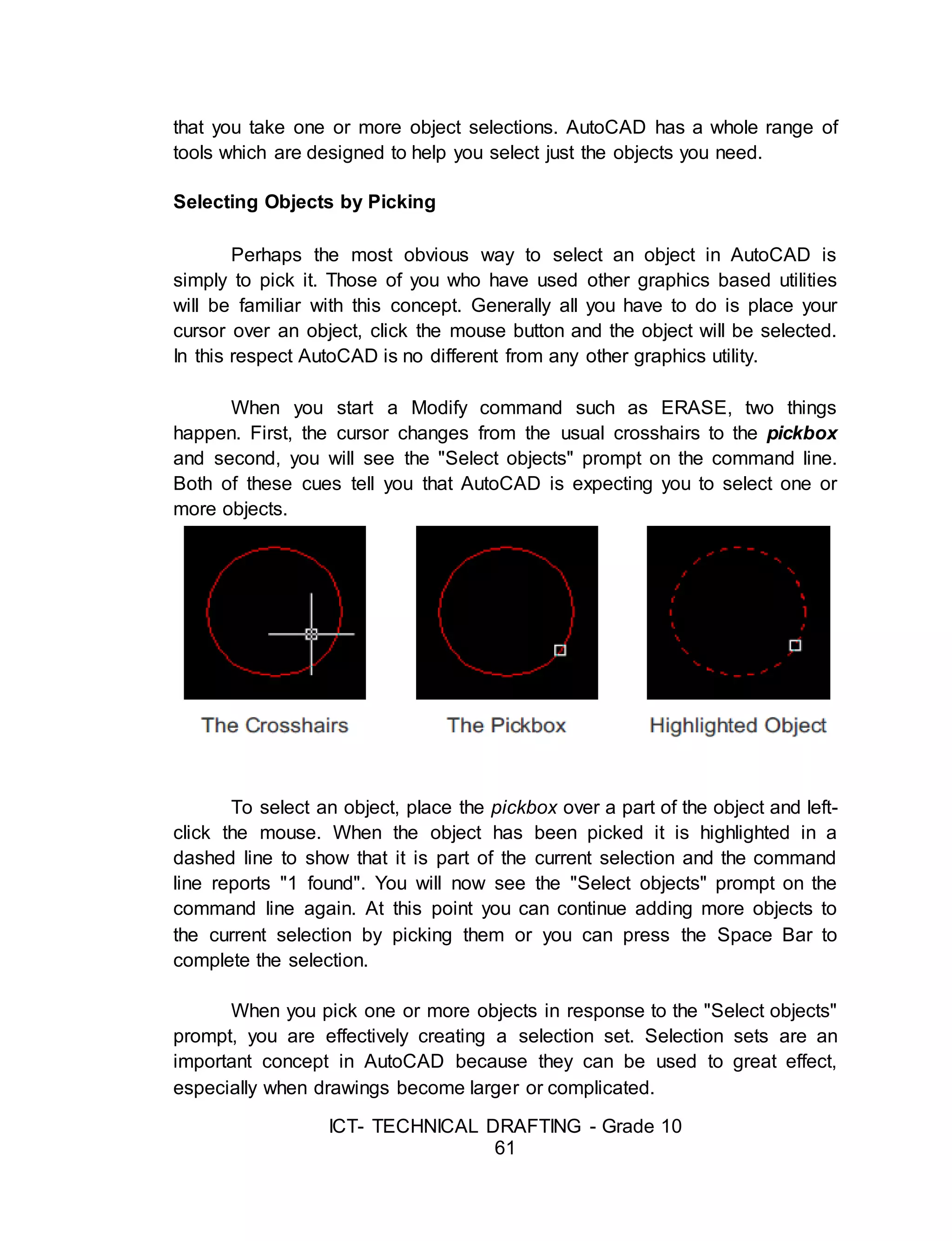
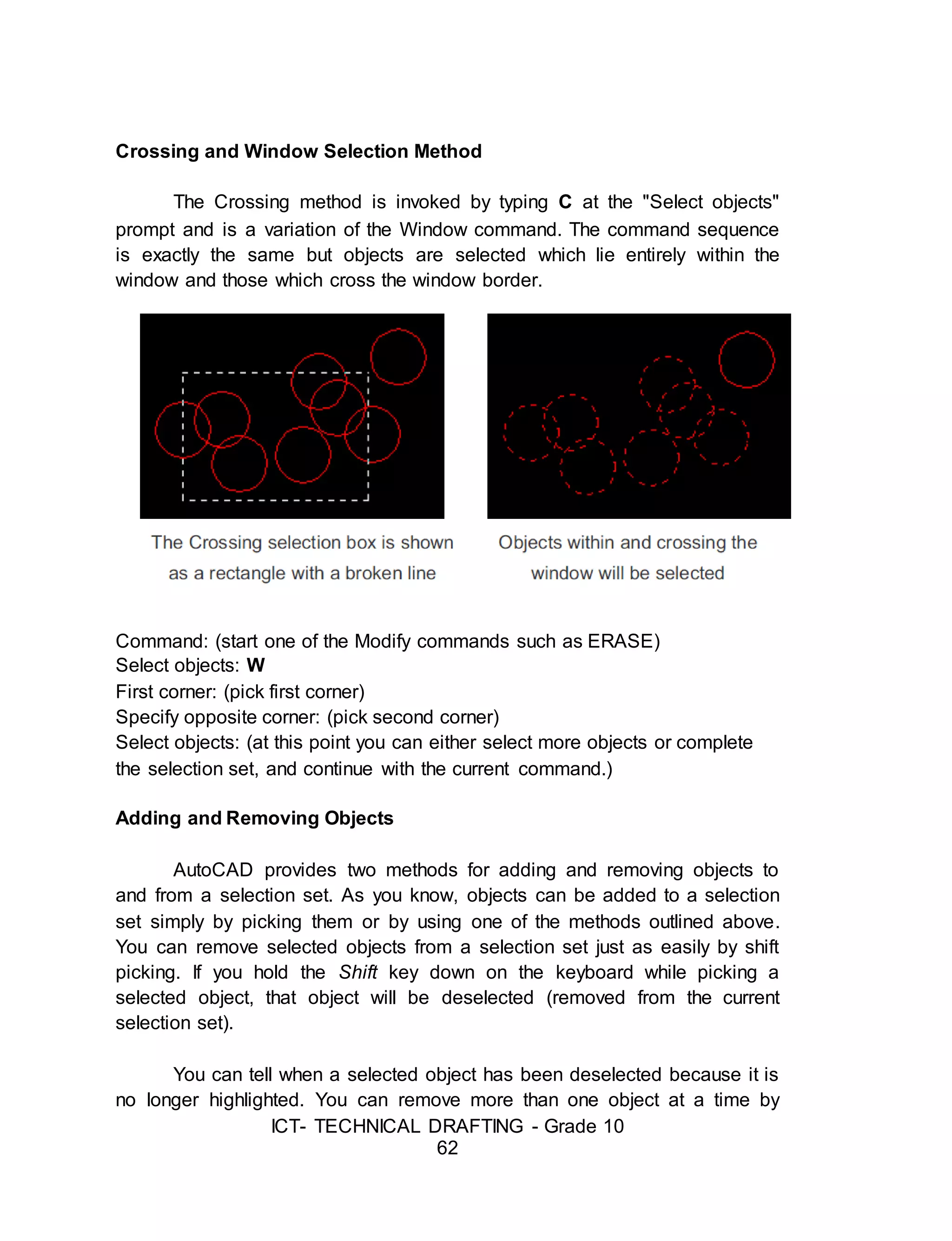
![ICT- TECHNICAL DRAFTING - Grade 10
63
holding down the Shift key while using implied windowing. However, none of
the other selection options which require keyboard input will work using the
shift pick method.
Tips: When you are picking objects in a complex drawing, use the ZOOM
command transparently to make object selection easier. All Zoom options selected
from the toolbars are automatically transparent but if you invoke the command from
the keyboard you will need to enter zoom.
Modifying Objects
AutoCAD drawings are rarely completed simply by drawing lines, circles
etc. Most likely you will need to modify these basic drawing objects in some
way or another in order to create the image you need. AutoCAD provides a
whole range of modify tools such as Move, Copy, Rotate and Mirror. As you
can see, the command names are easily understandable. However, the way
these commands work is not always obvious.
The Erase Command
The Erase command is one of the simplest AutoCAD commands and is
one of the most used. The command erases (deletes) any selected object(s)
from the drawing. Remember you can always get deleted objects back by
typing U to undo, from the Standard toolbar or by using the OOPS command.
Command: ERASE or E[enter]
Select objects: (pick an object to erase)
Select objects: (to end the selection and erase the object)](https://image.slidesharecdn.com/b-tdgrade10lmmodule3preparingcomputer-aideddrawing-170626104020/75/Technical-Drafting-Module-3-29-2048.jpg)
![ICT- TECHNICAL DRAFTING - Grade 10
64
The Copy Command
The Copy command can be used to create one or more duplicates of any
drawing object or objects which you have previously created. Copy is a very
useful and time-saving command because you can create very complex
drawing elements and then simply copy them as many times as you like.
Command: COPY or CO[enter]
Select objects: (pick object to copy, P1)
Select objects: (to end selection)
Specify base point or displacement, or [Multiple]: (pick P2 or M for multiple
copies)
Specify second point of displacement or <use first point as displacement>:
(pick P3)
The multiple option allows you to create additional copies of the selected
object(s) by picking as many new points as you like. To end a multiple copy,
just hit the key.
The Mirror Command
The Mirror command allows you to mirror selected objects in your
drawing by picking them and then defining the position of an imaginary mirror
line using two points.
Command: MIRROR or MI[enter]
Select objects: (pick object to mirror, P1)
Select objects: (to end selection)
Specify first point of mirror line: (pick P2)
Specify second point of mirror line: (pick P3)
Delete source objects? [Yes/No] <N>: (for No to keep the original object)](https://image.slidesharecdn.com/b-tdgrade10lmmodule3preparingcomputer-aideddrawing-170626104020/75/Technical-Drafting-Module-3-30-2048.jpg)
![ICT- TECHNICAL DRAFTING - Grade 10
65
The Offset Command
Offset is probably one of the most useful commands for constructing
drawings. The Offset command creates a new object parallel to or concentric
with a selected object. The new object is drawn at a user defined distance
(the offset) from the original and in a direction chosen by the user with a pick
point. You can offset lines, arcs, circles, ellipses, 2D polylines, xlines, rays
and planar splines.
Command: OFFSET or O[enter]
Specify offset distance or [Through] <1.0000>: 10 (specify distance)
Select object to offset or <exit>: (select object, P1)
Specify point on side to offset: (pick direction, P2)
Select object to offset or <exit>: (to end or select another object to offset)
The Move Command](https://image.slidesharecdn.com/b-tdgrade10lmmodule3preparingcomputer-aideddrawing-170626104020/75/Technical-Drafting-Module-3-31-2048.jpg)
![ICT- TECHNICAL DRAFTING - Grade 10
66
The Move command works in a similar way to the Copy command
except that no copy is made, the selected object(s) is simply moved from one
location to another.
Command: MOVE or M[enter]
Select objects: (pick object to move, P1)
Select objects: (to end selection)
Specify base point or displacement: (pick P2)
Specify second point of displacement or <use first point as displacement>:
(pick P3)
Note: The Copy command, the two pick points, P2 and P3 are used only to
indicate the distance and direction of movement.
The Rotate Command
The Rotate command allows an object or objects to be rotated about a point
selected by the user. AutoCAD
Command: ROTATE or RO[enter]
Current positive angle in UCS: ANGDIR=counterclockwise ANGBASE=0
Select objects: (pick object to rotate, P1)
Select objects: (to end selection)
Specify base point: (pick base point, P2)](https://image.slidesharecdn.com/b-tdgrade10lmmodule3preparingcomputer-aideddrawing-170626104020/75/Technical-Drafting-Module-3-32-2048.jpg)
![ICT- TECHNICAL DRAFTING - Grade 10
67
Specify rotation angle or [Reference]: (pick second point, P3 or enter angle)
Remember, by default, AutoCAD angles start at 3 o'clock and increase in
an anti-clockwise direction. The "ANGDIR" and "ANGBASE" variables remind
you of this. If you want to rotate in a clockwise direction you can enter a
negative angle by using a minus sign.
Note: You can change the angle direction and the base angle using the Units
command, Format Units… from the pull-down menu. Click the "Clockwise" check box
to change the direction and click the "Direction…" button to set the base angle.
The Scale Command
The Scale command can be used to change the size of an object or group
of objects. You are prompted for a pick point about which the selection set will
be scaled. Scaling can then be completed by picking a second point (not
always easy because it can sometimes be difficult to precisely control the
scaling) or by entering a scale factor at the keyboard. For example a scale
factor of 2 will double the size of the objects in the selection set and a factor
of 0.5 will reduce them into half.
Command: SCALE or SC[enter]
Select objects: (pick objects to be scaled, P1)
Select objects: (to end selection)
Specify base point: (pick base point, P2)
Specify scale factor or [Reference]: (pick second point, P3 or enter scale
factor)](https://image.slidesharecdn.com/b-tdgrade10lmmodule3preparingcomputer-aideddrawing-170626104020/75/Technical-Drafting-Module-3-33-2048.jpg)
![ICT- TECHNICAL DRAFTING - Grade 10
68
As shown above, the original tree symbol has been enlarged by
dynamically scaling it using pick points to determine the change in scale. If
you want to scale an object precisely, it is much easier to enter a scale factor
using the keyboard.
The Stretch Command
The Stretch command can be used to move one or more vertices of an
object while leaving the rest of the object unchanged. In the example below, a
rectangle has been stretched by moving one vertex to create an irregular
shape.
Command: STRETCH or S[enter]
Select objects to stretch by crossing-window or crossing-polygon...
Select objects: (pick first point of crossing window)
Specify opposite corner: (pick second point of window)
Select objects: (to end selection)
Specify base point or displacement: (pick base point)
Specify second point of displacement: (pick second point)](https://image.slidesharecdn.com/b-tdgrade10lmmodule3preparingcomputer-aideddrawing-170626104020/75/Technical-Drafting-Module-3-34-2048.jpg)
![ICT- TECHNICAL DRAFTING - Grade 10
69
Note: To select vertices to stretch, you must use a crossing window or polygon.
The Trim Command
The Trim command can be used to trim a part of an object. In order to
trim an object you must draw a second object which forms the "cutting edge".
Cutting edges can be lines, xlines, rays, polylines, circles, arcs or ellipses.
Blocks and text cannot be trimmed or used as cutting edges.
Command: TRIM or TR[enter]
Current settings: Projection=UCS Edge=None
Select cutting edges ...
Select objects: (select the cutting edge, P1)
Select objects: (to end cutting edge selection)
Select object to trim or shift-select to extend or [Project/Edge/Undo]:
(pick the part of the square which you want to trim, P2)
Select object to trim or shift-select to extend or [Project/Edge/Undo]:
(pick the circle, P3)
Select object to trim or shift-select to extend or [Project/Edge/Undo]: (to end)
Note: Notice that at each trimming step you are given the option to undo the
previous trim. This can be very useful if you inadvertently pick the wrong object.
The Chamfer Command](https://image.slidesharecdn.com/b-tdgrade10lmmodule3preparingcomputer-aideddrawing-170626104020/75/Technical-Drafting-Module-3-35-2048.jpg)
![ICT- TECHNICAL DRAFTING - Grade 10
70
The Chamfer command enables you to create a chamfer between any two
non-parallel lines as in the illustration below or any two adjacent polyline
segments. Usually, the Chamfer command is used to set the chamfer
distances before drawing the chamfer. Follow the command sequence below
where the chamfer distances are changed to 20 before the chamfer is made.
Command: CHAMFER or CHA[enter]
(TRIM mode) Current chamfer Dist1 = 10.0000, Dist2 = 10.0000
Select first line or [Polyline/Distance/Angle/Trim/Method]: D (to set distances)
Specify first chamfer distance <10.0000>: 20 (enter required distance)
Specify second chamfer distance <20.0000>:
(first distance value or enter a different value)
Select first line or [Polyline/Distance/Angle/Trim/Method]: (pick P1)
Select second line: (pick P2)
The chamfer is made and the command ends.
Note: Notice from the command sequence that there are a number of options
which can be used to control the way the Chamfer command behaves.
The Fillet Command
The Fillet command is a very useful tool which allows you to draw an arc
between two intersecting lines or adjacent polyline segments. You need first
to use the command to set the required radius and then a second time to
select the two lines.](https://image.slidesharecdn.com/b-tdgrade10lmmodule3preparingcomputer-aideddrawing-170626104020/75/Technical-Drafting-Module-3-36-2048.jpg)
![ICT- TECHNICAL DRAFTING - Grade 10
71
Command: FILLET or F[enter]
Current settings: Mode = TRIM,
Radius = 10.0000
Select first object or
[Polyline/Radius/Trim]: R
Specify fillet radius <10.000>: 25
Select first object or
[Polyline/Radius/Trim]: (pick P1)
Select second object: (pick P2)
The Fillet command can also be
used to fillet arcs and circles.
The "Polyline" option also allows
you to fillet all vertices of a
polyline with a single command.
Tips: Make sure that the
radius you specify will fit the objects
you select, otherwise the fillet
command will not work.
The Array Command
Using the Array command, you can duplicate existing objects in a
rectangle or circular (polar) pattern. You can select which type of array to use
in the Array dialog box. Click the Rectangular or Polar options to see point,
distance, and method requirements for each type.
The following illustration shows a rectangular and polar array.
Command: ARRAY or AR[enter]
Ribbon: Home tab > Modify panel > Array
Note: Do not confuse this command with the 3D Array command.
Menu Browser: Modify > Array](https://image.slidesharecdn.com/b-tdgrade10lmmodule3preparingcomputer-aideddrawing-170626104020/75/Technical-Drafting-Module-3-37-2048.jpg)
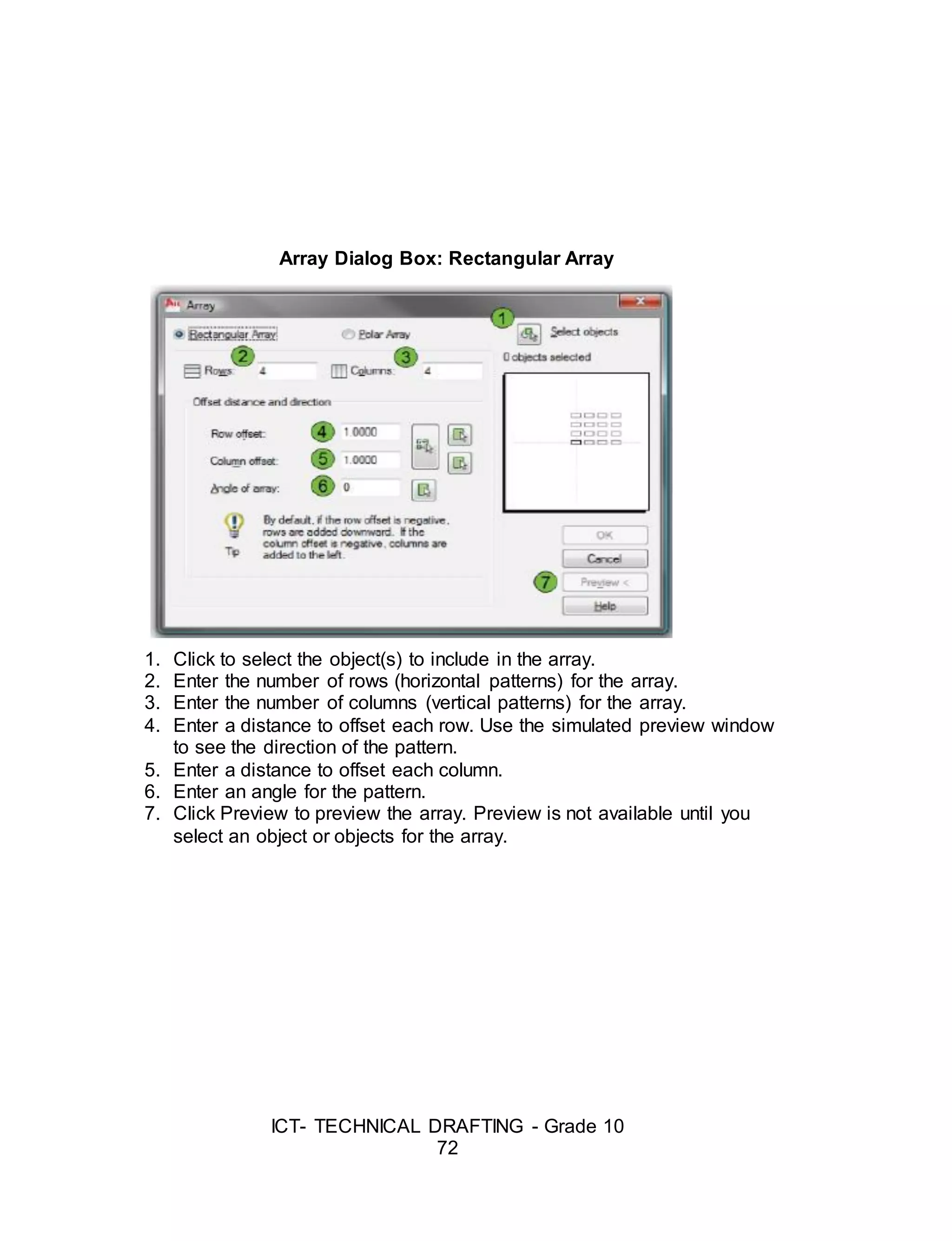
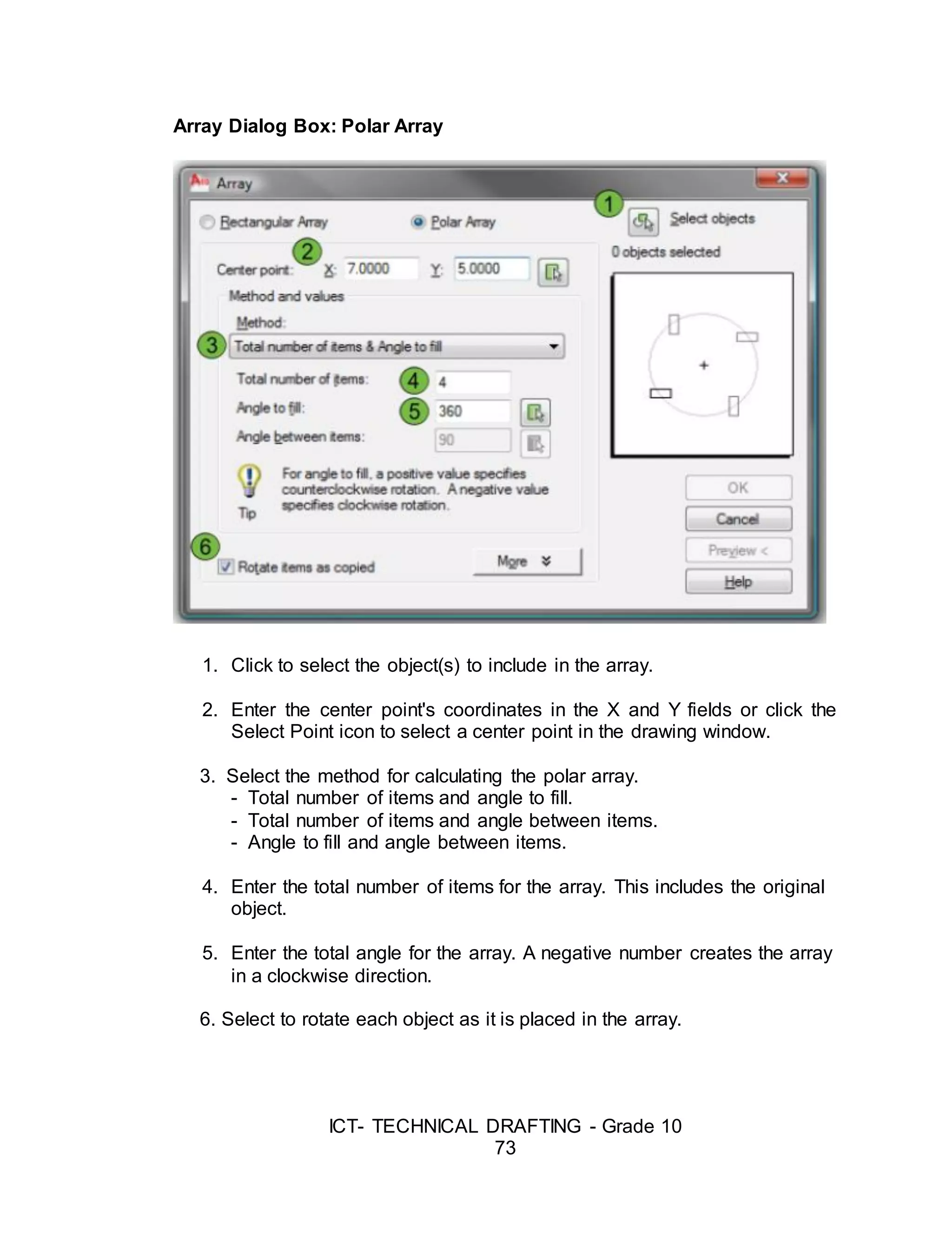
![ICT- TECHNICAL DRAFTING - Grade 10
74
Drawing Aids
Drawing with AutoCAD is really just like drawing on a drawing board. Most
new comers to Computer Aided Design assume that they will need to learn
how to draw all over again. In fact, many of the drawing aids that AutoCAD
provides are analogous to traditional drafting tools
Ortho Mode
Ortho is short for orthogonal, which means either vertical or horizontal.
Like the other options on the status bar, Ortho is not really a command, it is a
drawing mode which can either be turned on or off. Ortho mode can be
toggled on or off in one of three ways.
Command: ORTHO
Enter mode [ON/OFF] <OFF>: (type ON or OFF)
The Drawing Grid
The drawing grid is a regular pattern of dots displayed on the screen
which acts as a visual aid, it is the equivalent of having a sheet of graph
paper behind your drawing on a drawing board. You can control the grid
spacing, so it can give you a general idea about the size of drawn objects. It
can also be used to define the extent of your drawing.
Command: GRID
Specify grid spacing(X) or [ON/OFF/Snap/Aspect] <10.000>: (enter grid
spacing)
Snap Mode
Snap mode takes AutoCAD one step further than the drawing board. With
Snap mode turned on AutoCAD only allows you to pick points which lie on a
regular grid. The Snap grid is completely independent of the display grid.
Command: SNAP or SN[enter]
Specify snap spacing or [ON/OFF/Aspect/Rotate/Style/Type] <10.0000>:
(enter the required snap spacing in drawing units)](https://image.slidesharecdn.com/b-tdgrade10lmmodule3preparingcomputer-aideddrawing-170626104020/75/Technical-Drafting-Module-3-40-2048.jpg)
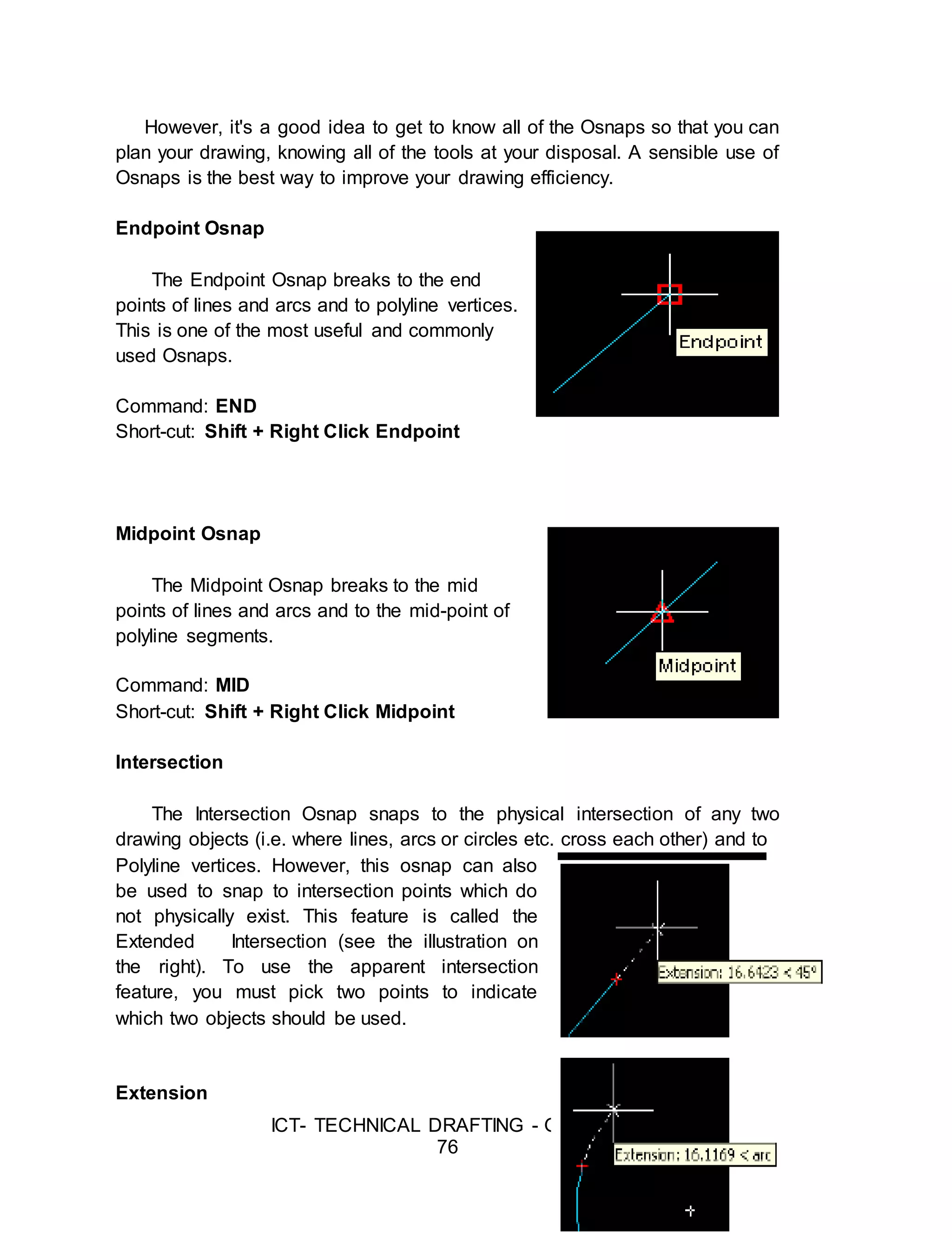
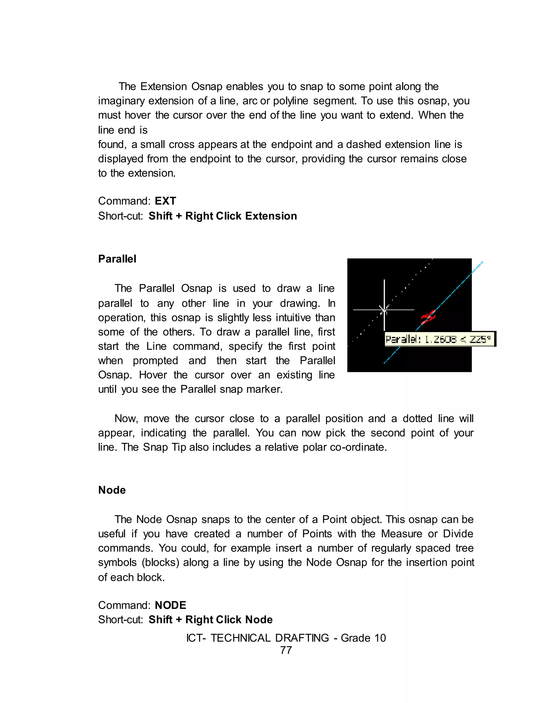
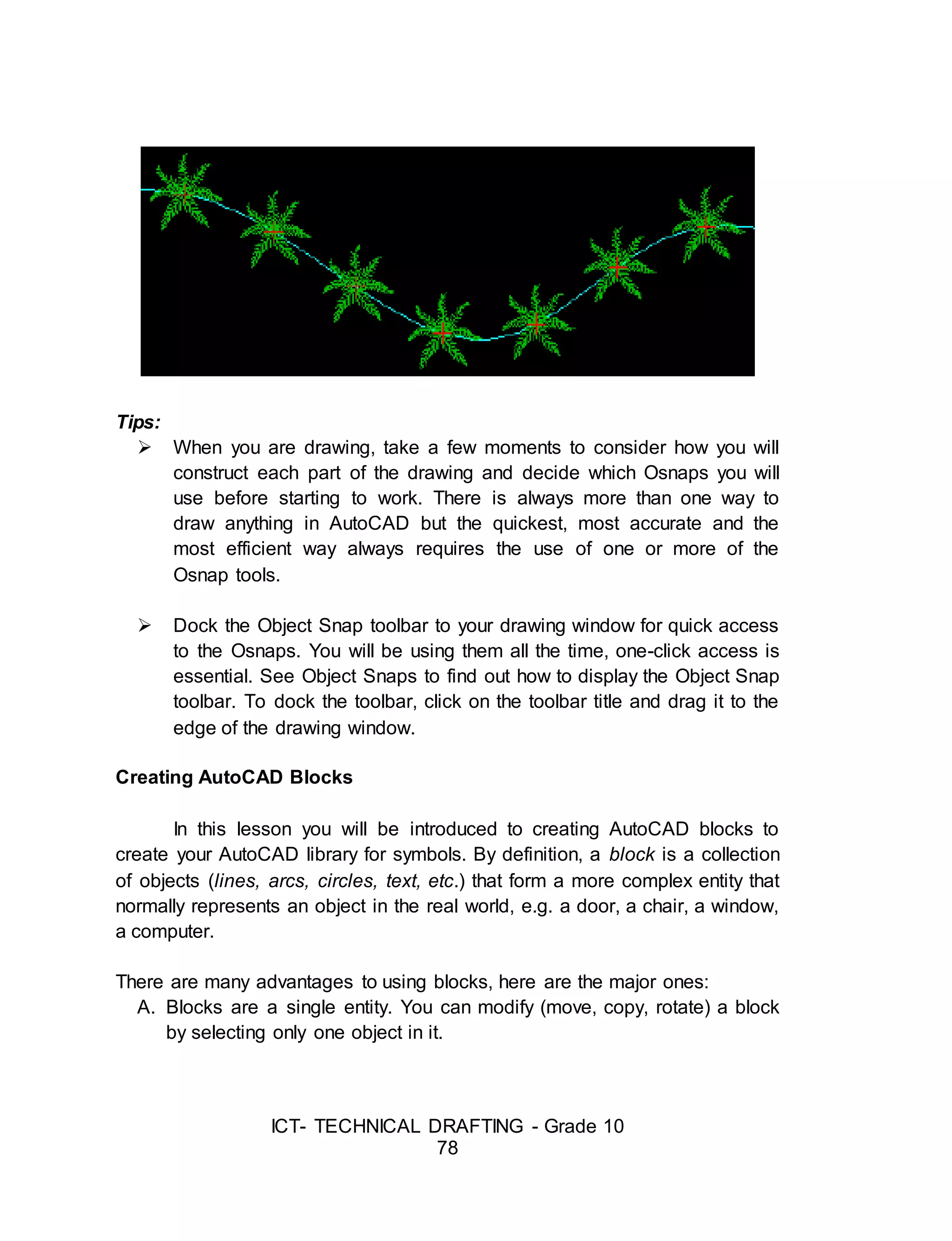
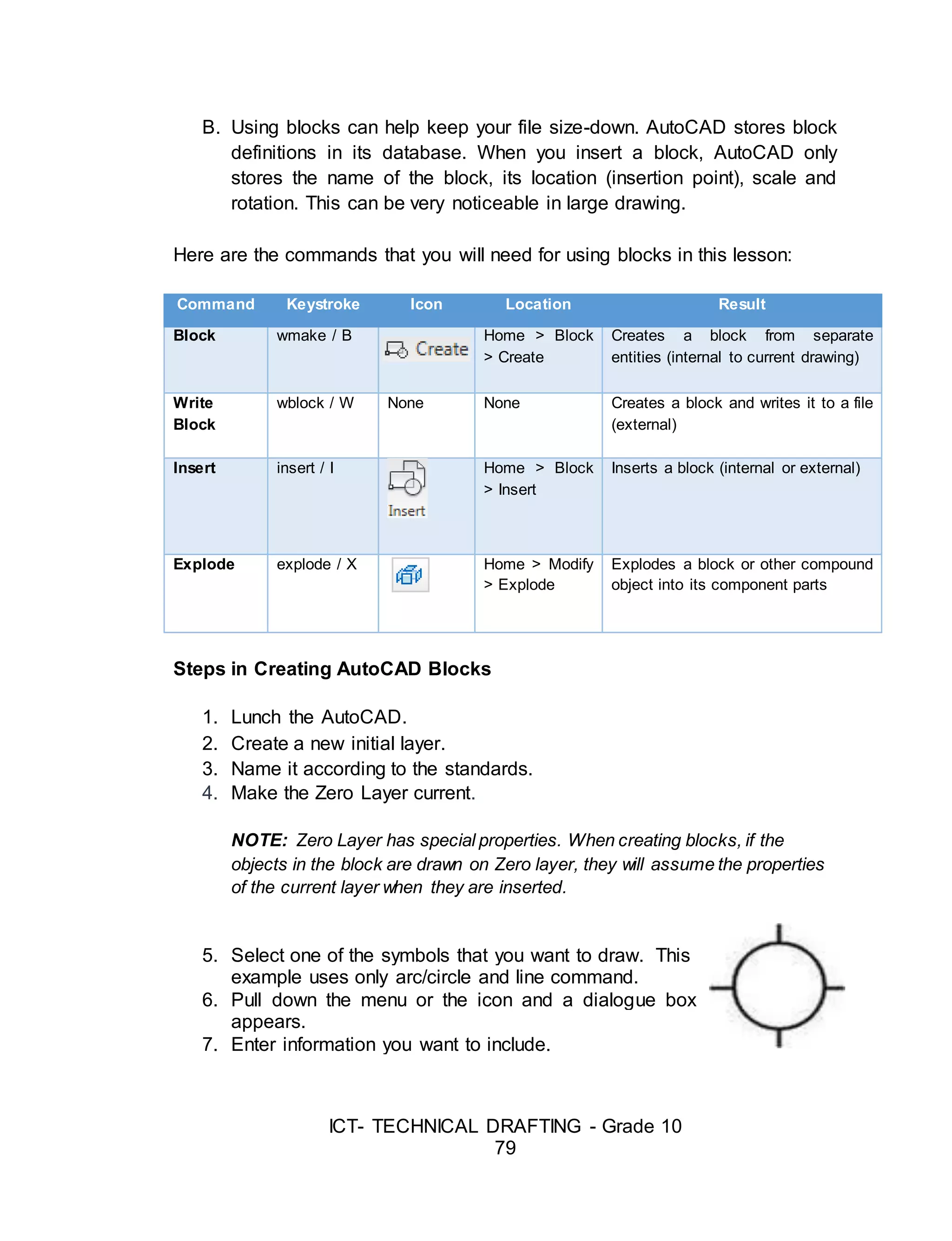
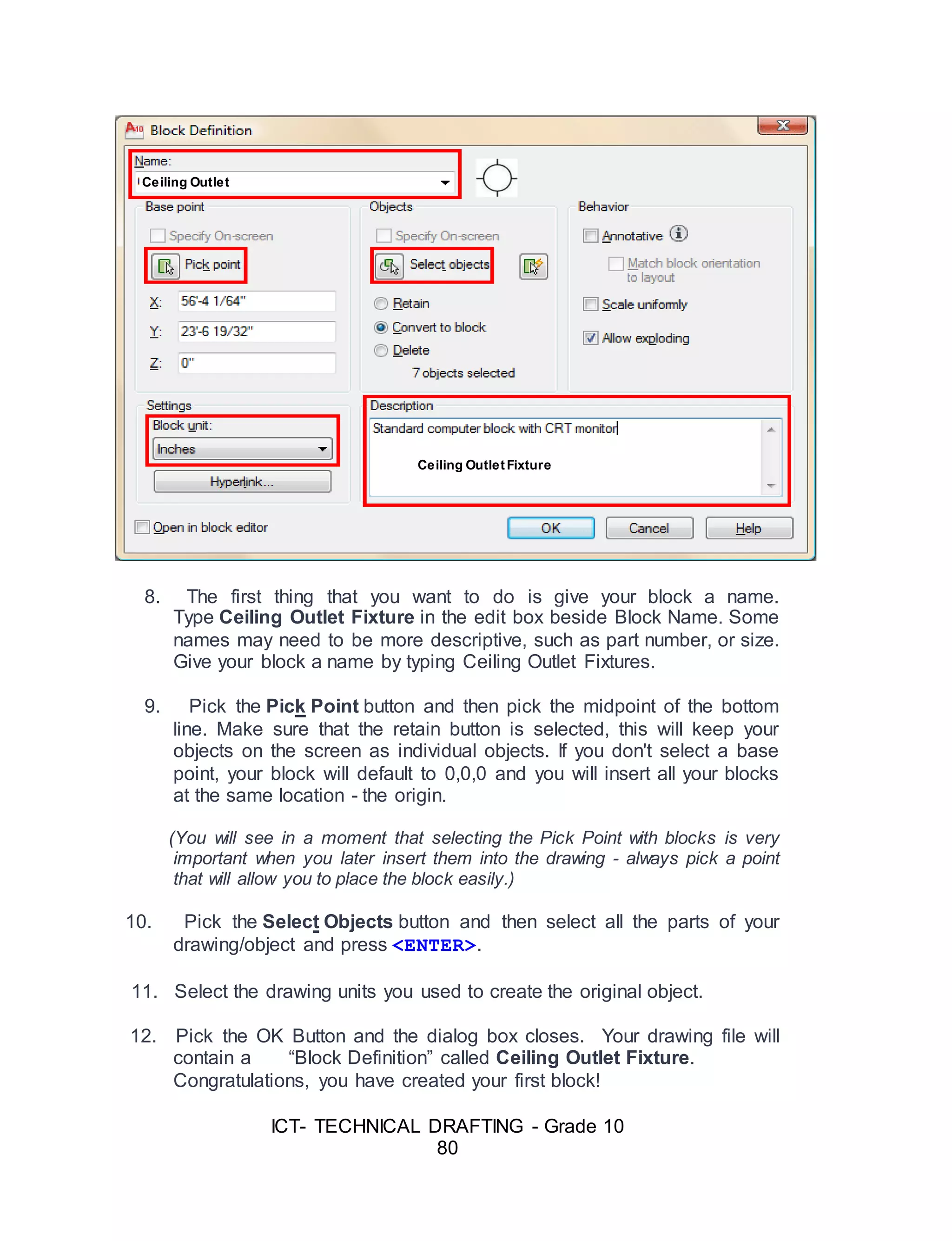
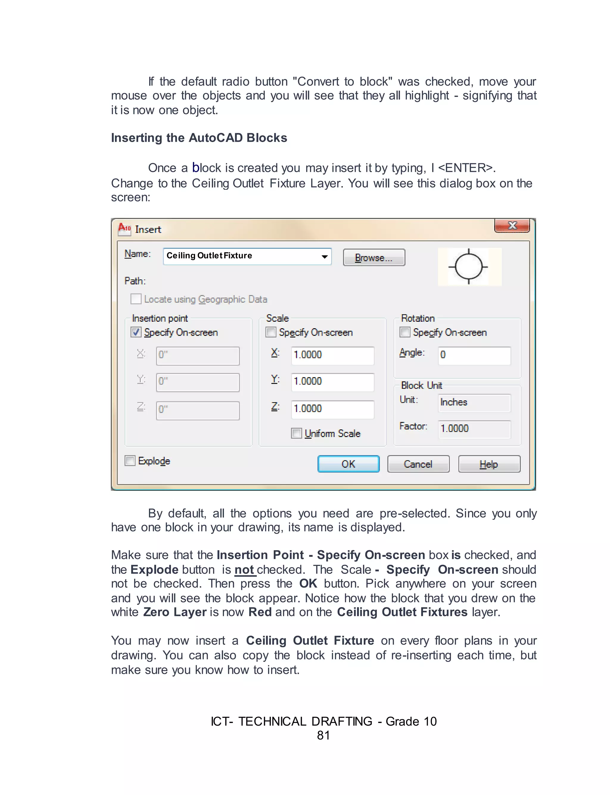
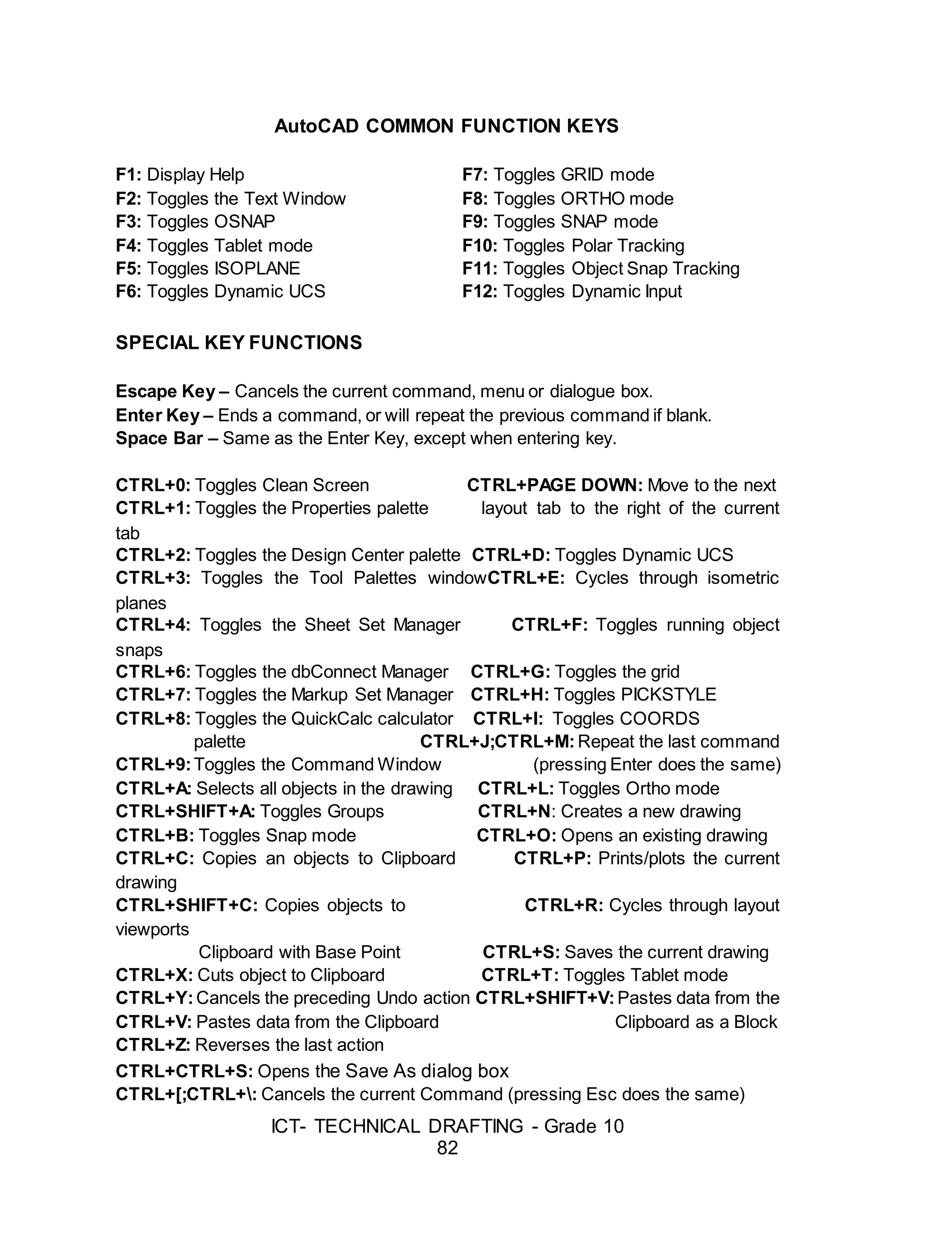
![ICT- TECHNICAL DRAFTING - Grade 10
83
CTRL+ PAGE UP: Moves to the next layout Tab to the left of the current tab
Now, you can simply draw lines by picking their position from the
workspace. If you want to draw lines with precise direction and length you can
use the Direct Distance Entry or the Relative Polar Coordinate.
Suggested Activity 1
Directions: Using the given drawing menu below, perform the following
tasks.
A. Draw Menu: LINE or L[enter]
By Picking
Command: LINE
Specify first point: (pick 1)
Specify next point or [Undo]: (pick 2)
Specify next point or [Undo]: (pick 3)
Specify next point or [Undo]: (pick 4)
Specify next point or [Undo]: press Enter Key
By Direct Distance Entry
Command: LINE
Specify first point: (pick)
Specify next point or [Undo]: (activate ortho enter the distance) 100
Specify next point or [Undo]: press Enter Key
B. Draw Menu: PLINE or PL[enter]
By Direct Distance Entry and Polar Coordinate
Command: PLINE
Specify start point: (pick 1)
Current line-width is 0.0
Specify next point or […]: (ortho ON and drag the mouse for desired
position) 400
Specify next point or […]: 200
Specify next point or […]: @300<30
Specify next point or […]: press Enter Key
Process](https://image.slidesharecdn.com/b-tdgrade10lmmodule3preparingcomputer-aideddrawing-170626104020/75/Technical-Drafting-Module-3-49-2048.jpg)
![ICT- TECHNICAL DRAFTING - Grade 10
84
C. Draw Menu: ARC or A[enter]
Command: ARC or A (press enter key)
Specify start point of arc or [Center]: (pick 1)
Specify second point of arc or [Center/End]: (pick 2)
Specify end point of arc: (pick 3)
Suggested Activity 2
1. Directions: With the suggested commands, draw the traffic signs
below in free size.
Suggested Commands:
REC, OFFSET, LINE, ROTATE, FILLET, HATCH, ERASE, ARC, CIRCLE,
TRIM, OSNAP, & ORTHO
Note: Assessment tool – Performance Rubrics (Refer to Appendix A)](https://image.slidesharecdn.com/b-tdgrade10lmmodule3preparingcomputer-aideddrawing-170626104020/75/Technical-Drafting-Module-3-50-2048.jpg)