This lecture describes the forms and shapes which can be fabricated by impact extrusion; it points out limiting factors in the freedom of design of impacts; it helps to learn about the factors affecting tolerances and surface roughness of impacts. Basic knowledge about the formability of metals and background in mechanical engineering is assumed.
TALAT Lecture 3505: Tools for Impact ExtrusionCORE-Materials
This lecture provides knowledge about design philosophy and tool materials for impact tools, which are a cost factor and eminently important for successful impact extrusion. Basic knowledge about the formability of metals and background in mechanical engineering is assumed.
The document provides information on impact extrusion processes, including definitions, classifications, process steps, and material flow and deformation characteristics. Impact extrusion involves pressing a workpiece through a die opening using a punch. There are different classifications based on tool type, material flow direction, workpiece geometry, and temperature. Key process variations include solid and hollow, forward and backward extrusion. Material flow is initially non-stationary but transitions to quasi-stationary. Strain is highest near the die opening and decreases radially. Punch and die designs impact stresses and mandrel movement.
This lecture gives definition and explanation of terms; it teaches the most important fundamental laws governing deep drawing; it explains special considerations for deep drawing of aluminium sheet metal. Background in production engineering and familiarity with the subject matter covered in TALAT This lecture 3701 is assumed.
Okay, let's calculate the center of pressure step-by-step:
1) Calculate Lx, Ly for each element using the given dimensions
2) Sum Lx = 6.25 + 9.25 + 7 + 5 + 4.25 + 1 = 32.75
3) Sum Ly = 25 + 7.05 + 12.8 + 12.5 + 4.5 + 1.57 = 63.42
4) X (distance from axis YY) = Sum Lx / Sum L = 32.75 / 32.75 = 2.5
5) Y (distance from axis XX) = Sum Ly / Sum L = 63.42 / 32.75 = 1.94
This chapter discusses sheet metal forming processes and equipment. It covers topics like shearing, bending, deep drawing, and other specialized forming techniques. Shearing is used to cut sheet metal blanks from larger sheets. Process parameters like punch and die shape, clearance, and speed affect shearing quality and forces. Bending involves plastic deformation by compression and tension forces. Minimum bend radii and springback compensation are discussed. Deep drawing uses a punch and die to form a sheet metal blank into a cup shape by stretching the metal. Factors like wrinkling, drawability, and blankholder forces are addressed.
This document provides an overview of sheet metal forming processes. It discusses shearing processes like punching and blanking. It describes the effects of clearance between the punch and die on shearing. It also covers other processes like bending, bead forming, flanging, roll forming, and stretch forming. Various press types and die configurations used in sheet metal forming are also summarized.
This document discusses various sheet metal forming processes and their characteristics. It provides tables comparing common sheet metal forming processes such as roll forming, stretching, drawing, stamping, and others. It also discusses specific sheet metal forming operations like bending, flanging, tube bending, and roll forming. Diagrams illustrate the mechanics and terminology used in these various sheet metal forming techniques.
Forging processes involve shaping metals by applying compressive forces. There are four main types: hammer/drop forging uses gravity impacts, press forging uses hydraulic or mechanical presses, and open-die and closed-die forging differ in whether dies fully contain the metal. Forging increases strength by working the metal and altering its microstructure. Proper die and process design are needed to control metal flow, fill dies completely, and minimize flash and defects. Die materials must withstand thermal and mechanical stresses, while coatings can extend die life.
This document is a student project on sheet metal die design using SolidWorks. It consists of an acknowledgements section thanking professors and engineers for their support. The abstract provides an overview of the project, which uses SolidWorks CAD tools and a geometry translator to design blanking and piercing dies for sheet metal parts. Chapter 1 introduces sheet metal working, the main tools involved including dies and machines, and provides examples of products made from sheet metal fabrication.
The document discusses various sheet metal forming processes. It describes cutting (shearing) operations such as punching, blanking, notching, etc. that stress the metal beyond its ultimate strength. It also discusses forming operations such as bending, drawing, squeezing, etc. that stress the metal below its ultimate strength. Various bending operations like V-bending, roll bending, and bead forming are also covered. The document discusses shearing and compound dies used for cutting operations. It also describes progressive, transfer, and hydroforming dies used for complex forming operations.
Sheet metal processes involve cutting, bending, and drawing operations. Shearing is the primary cutting operation used to cut sheet metal blanks from large sheets. It involves using a punch and die to cut along a straight line. Bending forms sheet metal by curving it around a straight axis and is done using V-bending or edge bending. Both cutting and bending can result in springback as the sheet tries to return to its original shape after forming. Process parameters like punch and die design, clearance, and lubrication affect the quality of cuts and bends in sheet metal fabrication.
Ch6 sheetmetw proc (1) Erdi Karaçal Mechanical Engineer University of GaziantepErdi Karaçal
The document discusses sheet metal working processes and cutting operations. It describes the three major categories of sheet metal processes as cutting, bending, and drawing. Cutting operations like shearing, blanking, and piercing are used to separate sheet metal into pieces or make holes. Proper die clearances and cutting forces must be considered for optimal cutting. Tools called punches and dies are used to perform these operations on stamping presses.
Datum Features:
Functional datum, datum for manufacturing, changing the datum;examples.
Component Design:
Design features to facilitate machining: drills, milling cutters, keyways, Doweling procedures, counter sunk screws, Reduction of machined area, simplification by separation, simplification by amalgamation, Design for machinability, Design for economy, Design for clampability, Design for accessibility. Design for assembly
Sheet metal stamping was developed in the 1890s for mass production of bicycles, playing an important role in making interchangeable parts economical. Basic sheet forming processes include shearing, bending, drawing, and involve tools like shear presses, brake presses, and finger presses. Material selection is critical, balancing formability with strength, weight, cost, and corrosion resistance. Stretch forming allows tighter tolerances than stamping but is difficult for complex shapes. New developments include tailored blanks, binder force control, and quick die exchange. Alternative auto body materials offer cost and environmental benefits compared to steel.
TALAT Lecture 3702: Tribology in Cold Forming of Aluminium SheetCORE-Materials
This document provides an overview of tribology and friction in cold forming of aluminum sheet metal. It discusses:
1) The importance of friction in sheet metal drawing and the different friction zones that exist. Both low and high friction is needed in different areas to control material flow.
2) How the microtopography of the sheet surface impacts friction and the mechanisms of friction. Surface treatments can make the surface isotropic and better retain lubricant.
3) Tests used to measure friction coefficients in strip drawing tests that simulate the forming process. Surface properties greatly influence friction behavior.
4) The tribological system involves the sheet surface, tool surface, and lubricant working together to prevent adhesion. Both surface roughness
This document discusses the design of piercing and blanking dies and punches for cutting flat washers from aluminum and copper alloys. It provides calculations for cutting force, clearance, punch and die sizes for different materials. It also includes the design of springs, stripper plate thickness and die block thickness. Key specifications calculated include a punch diameter of 10.77mm, die diameter of 11.0686mm, blanking punch diameter of 19.7014mm, blanking die diameter of 20mm, spring wire diameter of 18mm and coil diameter of 72.08mm.
This document provides an overview of designing stamping dies, specifically blanking dies. It discusses:
1. The basic components and structure of standard blanking dies, including the upper and lower die sets, punch, stripper, and die holder.
2. The design flow for blanking dies, including blanking layout, stripper design, punch design, and assembly of the die sets.
3. Key considerations for individual die components like providing sufficient clearance and distances between parts, and designing punches, strippers, and die holders to simplify fabrication and assembly while withstanding forces during stamping.
Extrusion and drawing are metal forming processes that involve pushing or pulling metal through a die to reduce or change its cross-sectional area. Extrusion is used to produce parts like tubing, rails, and structural shapes, while drawing produces wires, rods, and small parts. Both processes can work metals at either room temperature or higher temperatures depending on the material's ductility. Proper die design is important for efficient extrusion or drawing with considerations for the workpiece geometry, corners, and thickness changes.
Drill bits are cutting tools used to create cylindrical holes. They are held in a chuck and rotate to provide torque and force. Specialized bits can create non-cylindrical holes. Common drilling operations include reaming to enlarge holes, tapping to cut internal threads, counterboring, and countersinking. Twist drill bits are the most commonly used type and have a cylindrical shaft and helical flutes.
Sheet metal forming is a versatile manufacturing process used to produce lightweight parts with complex shapes. Common forming operations include punching, blanking, bending, deep drawing, and stamping. Key considerations in sheet metal forming include the material properties, forming limits, stresses induced during forming, and techniques to reduce waste and improve dimensional accuracy. Proper tool and die design is critical for successful forming of sheet metal parts.
This document provides an overview of forging and press working processes. It defines forging as plastically deforming metal at elevated temperatures using compressive forces. The document classifies forging methods as open die, closed die, drop, hammer, and press forging based on the process and equipment used. It also defines press working and classifies press types and operations including cutting operations like blanking and punching, and forming operations like bending and drawing. Key tools for forging like hammers, tongs, and dies are also introduced.
This document provides an overview of forging and press working processes. It defines forging as plastically deforming metal under compressive force at elevated temperatures using tools like hammers or presses. Forging is classified as open die or closed die based on the tools used, and as hammer, press, drop or machine forging based on the equipment. Press working involves shaping sheet metal between dies in a press machine. Common press working operations include cutting via blanking, punching and forming through bending and drawing.
This seminar discusses the design and manufacturing of bearing cups. It describes the different types of presses and dies used in the process, including blanking, piercing, and drawing dies. Calculations are shown for determining the required forces for each operation. The total force required for the compound die is estimated to be 8.4 tons. The cost of manufacturing the die is estimated to be Rs. 9000. The seminar concludes that bearing cups can be efficiently manufactured in batches of 6000 using this compound die.
This document discusses sheet metal forming processes. It introduces various sheet metal forming methods like bending, stretching, deep drawing, and identifies common defects. The objectives are to describe sheet metal forming processes, discuss variables that affect formability, and emphasize defects and solutions. Various forming equipment, stresses involved, and classifications of sheet metal parts and processes are outlined over several pages.
The document discusses various sheet metalworking processes including cutting, bending, and drawing. Cutting operations like shearing, blanking, and punching are used to cut sheet metal. Bending involves straining sheet metal around a straight axis using methods like V-bending and edge bending. Drawing forms sheet metal into convex or concave shapes. Key considerations in sheet metalworking are clearance, bending allowances, springback, and forces required for cutting.
1. The document describes the design and analysis of a punching die. It aims to design an interchangeable die and punches to reduce weight by changing materials.
2. The die set is designed to perform individual operations at each station with a single press stroke, unlike a progressive die. The parts are designed in SolidWorks and analyzed using SimulationXpress.
3. The die, punches, and guide pins are made of LM6 alloy for its light weight and hardness. The bottom plate is designed to provide space for die operations while withstanding bending stresses well below its limits.
Rod, wire and tube drawing is a metalworking process where a rod, wire or tube is pulled through a die to reduce its cross-sectional area and increase its length. It involves applying both tensile and compressive forces. Products include wire, rods, and tubes used in applications like electrical wiring, springs and hydraulic tubing. The process offers close dimensional control, lower costs than rolling or extrusion, and can produce very small cross-sections. Lubrication and annealing are important to control work hardening during multiple drawing passes. Dies are commonly made of alloy steels, carbides or diamond to withstand wear from the process.
Enter the Art of Extrusion
Alumat & Almax Mori Group investments, through the lens of fine arts
In a time of crisis and economical challenges, the choice of Alumat and Almax Mori group has been investing – new persons, new machinery, new plant, new technologies, new services.
13% of the Group’s annual turnover has been invested to improve products and processes.
The result: increased quality and efficiency, both for our internal processes and for the products.
Producing better, delivering faster, satisfying more and more customers with advanced solutions that bring extrusion to the state of an Art.
Start the voyage now, we’ll be beside you day after day.
Alumat & Almax Mori Group – Choose ahead.
Simulation aided design of portholes for magnesium extrusionAlumat Almax Group
Simulation aided design of Portholes for magnesium extrusion.
Paper presented at ET12, written by Tommaso Pinter1, Yoram Rami2, Tuvia Kornfeld3, Antonio Segatori4 , Lorenzo Donati4 , Luca Tomesani4
1 Almax Mori S.r.l., Mori - Italy
2 Alubin, Kiryat Bialik - Israel
3 N.T.K Ltd., Shechanya - Israel
4 University of Bologna, Bologna - Italy
The document discusses the process of extrusion where a billet is forced through a die to produce parts with constant cross-sections. There are three main types of extrusion processes - direct, indirect, and hydrostatic. Direct extrusion involves a ram forcing the billet through the die, indirect uses a moving die, and hydrostatic uses fluid pressure. Extrusion can be performed hot or cold, with hot extrusion reducing required forces but cold extrusion increasing strength. Process variables like temperature, speed, and lubrication affect extrusion pressure. Potential defects include surface cracking, pipe formation, and internal cracking.
This lecture provides a background on aluminium alloys suitable for impact extrusion. It draws attention to raw material parameters which may affect the properties of impact extruded parts. Basic knowledge about the formability of metals and background in mechanical engineering is assumed.
TALAT Lecture 3801: Manufacturing Examples and FundamentalsCORE-Materials
This lecture describes the fundamentals of the superplastic behaviour phenomenon of aluminium alloys and the basic process parameters which govern the manufacturing of superplastic sheet metal parts. General background in production engineering and material science is assumed.
TALAT Lecture 3503: Finishing and other Supplementary OperationsCORE-Materials
This lecture describes supplementary fabrication measures for impact extruded parts and gives some examples of finished impacts. Basic knowledge about the formability of metals and background in mechanical engineering is assumed.
TALAT Lecture 2301: Design of Members Example 4.4: Bending moment resistance ...CORE-Materials
This 3 sentence summary provides the key details about the document:
1) The document is a 10 page example from a lecture on designing members for bending moment that analyzes the bending moment resistance of a welded hollow section with outstands using a class 4 cross section.
2) It presents the geometry, material properties, nodes, and elements of the hollow cross section and performs iterative calculations of the effective cross section area, stress distribution, and effective thicknesses accounting for any heat affected zones to determine the bending moment resistance.
3) The example is considered comprehensive because it shows calculations in detail, covers all classes of cross sections, and demonstrates how to increase effective thickness for non-fully stressed elements through
This lecture helps to understand how the properties of forgings evolve during the manufacturing process. General understanding of metallurgy and deformation processes is assumed.
This lecture describes fabrication processes for superplastic forming, i.e. female and male die forming, and the criteria for selecting the correct process. General background in production engineering and material science is assumed.
TALAT Lecture 2301: Design of Members Example 5.5: Axial force resistance of ...CORE-Materials
This 3-page document provides an example calculation for determining the axial force resistance of a laced column. It includes dimensions, material properties, and calculations of various parameters needed for the analysis. Key steps and results are shown, such as determining the effective length, flexural buckling resistance, and checking that the lacing can resist the required shear force. In the end, it is determined that the lacing can adequately resist the applied axial load of 270 kN.
This document provides an overview of application characteristics for rivet and clinch joints. It discusses design considerations such as choosing rivet diameters and distances from edges. It also covers material and tooling parameters that influence joint quality like surface finish. Testing methods are described for shear-tensile, fatigue, and impact tests. Sample geometries and results are shown. Finally, it briefly discusses cost considerations for different joining technologies.
TALAT Lecture 5104: Basic Approaches to Prevent Corrosion of AluminiumCORE-Materials
This lecture describes important measures for the prevention of corrosion of unprotected, bare
aluminium. Basic knowledge of corrosion behaviour of aluminium and some knowledge of the electrochemical nature of corrosion is assumed
TALAT Lecture 4205: Testing Methods for Welded JointsCORE-Materials
This lecture gives information about the relevant non-destructive and destructive testing methods for aluminium welded joints. Background in production welding and quality assurance is assumed.
This lecture describes the factors important for the quality assurance of adhesive joining; it gives information about the destructive and non-destructive testing methods for the quality control of adhesive joining. General background in production engineering and material science, some knowledge of mechanics and polymer science is assumed.
This lecture describes the detailed processes of single-step and multiple-step clinching; it shows the differences of the various clinching methods concerning the amount of shearing; it illustrates the major differences in mechanical properties of clinch joints compared with resistance spot welds. General mechanical engineering background and familiarity with the subject matter covered in TALAT This lecture 4101 is assumed.
TALAT Lecture 4702: Factors Influencing the Strength of Adhesive JointsCORE-Materials
This lecture describes the factors governing the strength of adhesive joints in order to appreciate these factors for the design of adhesively bonded joints, i.e. geometry of joint, stiffness and strength of the adjoining parts, stress distribution in the adhesive layer as well as the effects of humidity and ageing. General background in production engineering and material science, some knowledge of mechanics and polymer science is assumed.
TALAT Lecture 4107: General Summary and Future TrendsCORE-Materials
This lecture points out the need of data sources for designing mechanical joints; it describes concepts for FEM-Modelling of mechanical joints. General mechanical engineering background and familiarity with the subject matter covered in TALAT This lectures 4101- 4106 is assumed.
TALAT Lecture 4703: Design and Calculation of Adhesive JointsCORE-Materials
This lecture describes the basic types of loadings of adhesive joints and to give examples of recommended joint designs; it shows how to calculate the strength of adhesive joints. General background in production engineering and material science, some knowledge of mechanics and polymer science is assumed.
This lecture describes the fundamentals of bending and folding aluminium sheet; it also describes different methods in design of folding tools. Background in production engineering and sheet metal forming and familiarity with the subject matter covered in TALAT This lectures 3701- 3705 is assumed.
TALAT Lecture 2101.01: Understanding aluminium as a materialCORE-Materials
This lecture is an introduction to aluminium alloys, fabrication methods and properties. It provides information about the classification of aluminium alloys, new alloys and composites; shaping processes, processing chains and component shapes; microstructure and the interaction between microstructure and properties. It promotes understanding of the fact that the correct choice of materials demands knowledge of alloys, shaping processes and microstructure and the interaction among them. The lecture is recommended for those situations, where a brief, general background information about aluminium is needed as an introduction of other subject areas of aluminium application technologies. This lecture is part of the self-contained course "Aluminium in Product Development", which is treated under TALAT lectures 2100.
This document discusses sheet metal forming processes. It describes that sheet metal is used widely in consumer and industrial products. The most common materials used are low-carbon steel, aluminum, and newer high-strength steels. The main forming processes discussed are shearing, die cutting, fine blanking, laser welding of tailor-welded blanks, and bending of sheets, plates and tubes. Shearing involves using a punch and die to cut the sheet metal and produces rough edges that can be further processed through additional operations like shaving.
IRJET- Comparative Analysis on Seismic Behavior of R.C.C, Composite Encased a...IRJET Journal
This document compares the seismic behavior of 12-story buildings constructed of reinforced concrete (RCC), composite enclosed, and composite infilled framing subjected to equivalent static and response spectrum analysis. Four models of each framing type are analyzed with different shear wall configurations. The buildings are modeled in ETABS software assuming properties for seismic zone III in India. Results for parameters like story drift, period, frequency, displacement, and base shear are compared. Preliminary findings indicate that composite framed structures perform well seismicly, especially for shear wall configuration 1.
Concreat filing information about K007en.pdfthinagara
This document provides information on steel sheet pile products made by Nippon Steel & Sumitomo Metal Corporation. It summarizes their hat-type sheet pile product called NS-SP-900, which offers advantages over conventional sheet piles like improved drivability and cost-effectiveness due to a reduced amount of steel required per wall. It also describes their U-type sheet pile products, which come in a range of section modulus and have been widely used in permanent and temporary structures. The document provides details on the material quality, shapes, dimensions and properties of both hat-type and U-type sheet pile products.
Analysis of Multi-Storey Steel Structure with Different Infills and Steel Bra...IRJET Journal
This document analyzes the seismic performance of a 9-story steel structure with different bracing and infill systems through modeling and analysis. Four structural models are considered: a bare frame, bare frame with precast panel infill, bare frame with X-bracing, and bare frame with X-bracing and precast panel infill. The models are analyzed using software to determine base shear, story drift, and displacement under seismic loads. Results show that use of bracing and infills helps reduce displacement and story drift, with the model containing both X-bracing and precast infill performing best by minimizing drift. Infill and bracing systems thus improve the structure's lateral stiffness and strength during earthquakes.
In general, aluminium alloys have excellent machining properties compared with other common engineering metals.The lecture describes the machinability of aluminium alloys, the necessary tools and equipments in order to obtain optimum results. General background in production engineering and machine tools is assumed.
Aluminum extrusion operations vary from project to project, depending on the part and production specifications. However, in general, they follow the same basic process, which includes the following steps:
Formwork is used to create structures out of concrete that is poured into molds. It can be made from materials like steel, wood, aluminum, or prefabricated forms. Construction of formwork takes up 20-25% of total structure costs and involves supporting structures and molds. Proper formwork is designed to be easily removable, economical, leakproof, durable, rigid, provide smooth surfaces, be strong, and have adequate supports. Common types include conventional timber formwork, engineered prefabricated formwork, and modern systems like flying forms. Materials used include steel, plywood, plastic, and aluminum. Proper bracing and construction is needed to avoid failures from improper stripping, inadequate bracing, vibration
The document discusses steel structures and structural drafting. It covers various topics related to steel including properties, structural joints, technical terms, and design elements. Specific sections are dedicated to steel columns, plate girders, purposes and uses of steel, advantages and disadvantages of steel structures, steel structure drawings, working drawings, fabrication, and roof systems of steel trusses. The document provides information needed for structural drafting and elementary structural design.
This document provides an overview of sheet metal forming processes. It discusses both cutting (shearing) operations like punching, blanking, and notching as well as forming operations like bending, drawing, squeezing, and hydroforming. The document describes various bending operations including V-bending, roll bending, and tube bending. It also discusses processes for forming parts like deep drawing, ironing, redrawing, and the multi-step metal forming process used to produce aluminum beverage cans.
This document summarizes friction stir welding (FSW), including its working principle, microstructure analysis, tool design, process parameters, advantages, challenges, and applications. FSW is a solid state welding technique that uses a rotating tool to generate frictional heat and mechanically deform aluminum alloys below their melting point. It produces high quality welds with improved mechanical properties compared to fusion welding. Main applications are in shipbuilding, aerospace, and automotive industries.
This document summarizes key requirements for ductile detailing of reinforced concrete structures according to IS 13920:2016. It discusses the importance of ductility in allowing structures to resist seismic forces through inelastic deformation without collapse. Requirements are provided for ductile detailing of beams and columns, including minimum steel grades, reinforcement ratios and spacing, hook and lap splice details, and confinement reinforcement. The goal of ductile detailing is to avoid brittle failures and ensure ductile behavior through controlled yielding of steel reinforcement.
A Review on Optimization of the Process Parameters in Friction Stir Welding o...IJAEMSJORNAL
This study is describing a simple and systematic methodology for optimizing the Process parameters of friction stir welding (FSW) of (AA6105 and AA6082) aluminium alloy using Taguchi technique. The main focus of this review paper is to discuss FSW principle, process parameter and mechanical properties. The current study focuses on the friction stir welding of wrought aluminium alloys 6082 and aluminium alloy 6105 that are commonly used in the structural and automotive industries. Apart from this paper FSW process has been done on various aluminium alloys but dissimilar friction stir welding of these two materials are not reported in their research. A systematic study has been performed on the joint properties on the dissimilar welding of the selected materials and their relationships between various parameters.
The PPT is prepared to create awareness in practicing civil engineers to minimize the mistakes in construction so as to enhance the stability and durability of structures
IRJET- A Review on Microstructure and Mechanical Properties of Aluminium Allo...IRJET Journal
The document reviews the effects of mechanical vibration on the microstructure and mechanical properties of aluminum alloys cast using gravity die casting. It discusses how applying vibration to the mold during casting can refine grain structure and reduce dendrite arm spacing and defects. Several studies cited found that vibration led to higher tensile strength, hardness, and impact strength in cast aluminum alloys by promoting fragmentation of dendrites and a more homogeneous temperature field during solidification. The literature review concluded that vibration casting improves mechanical properties by changing the microstructure through effects on solidification like reducing grain size.
The document discusses general design considerations for metal castings. It notes that successful casting requires controlling variables related to the metal, casting method, mold materials, mold design, and process parameters. It describes steps for robust casting design, including designing the part for easy casting, selecting suitable materials and process, locating parting lines and gates, and including features like risers. It also discusses avoiding defects by modifying part geometries, allowing for shrinkage, adding drafts and finishes, and considering post-casting machining needs.
This document provides an overview of a course on metal forming processes. It discusses the main types of metal forming processes including bulk metal forming, sheet metal forming, and powder metal forming. The course will cover topics such as material behavior in metal forming, temperature effects, friction and lubrication, as well as specific processes like forging, rolling, extrusion, and drawing. It provides learning objectives, course content, required textbooks, and information on assignments, grading, and the class schedule.
IRJET-Analysis and Optimization of Cutting Parameters in Turning using Tic -...IRJET Journal
This document analyzes and optimizes cutting parameters in turning chrome-moly alloy steel using TiC-coated carbide inserts. Twenty-seven experiments were conducted using a L27 orthogonal design to evaluate the effects of cutting speed, feed rate, and depth of cut on surface roughness, power consumption, chip reduction coefficient, and tool wear. The results show that feed rate and depth of cut significantly affect surface roughness, while cutting speed, depth of cut, and feed rate influence power consumption and tool wear. Optimizing these cutting parameters can improve the machining performance and surface quality when hard turning chrome-moly alloy steel.
A STUDY AND DESIGN ANALYSIS FOR INJECTION MOULD FOR PLASTIC BEARINGIRJET Journal
This document summarizes a study on the design and analysis of an injection mold for a plastic bearing component. It discusses the objectives of the study, which are to gain detailed knowledge of mold making techniques and manufacturing processes. It then provides details on the component analysis, including properties of the material (nylon 66) and specifications of the mold. Key factors considered in the tool design are also summarized, such as parting line, feeding system, cooling and ejection. The document further provides details on the selection of raw materials for the mold, including various steel grades used and how alloying elements affect the properties of the steel. Finally, it summarizes the terminology and descriptions of the main mold parts.
Similar to TALAT Lecture 3504: Impact Extrusion Design Aspects and Properties (20)
Series of powerpoint slides showing three different drawing processes used in the manufacture of wires, rod, tubes and drinks cans. The slides are adapted from the University of Liverpool "Materials Processing" lectures [MATS214] by Dr J. Wilcox.
The document describes several test geometries used to determine the failure strengths of composite materials, including the Double Cantilever Beam test for mode I failure, the End Notch Flexure test for mode II failure, and the Mixed-mode Interlaminar Fracture test for mixed mode I/II failure. It also lists the Single Cantilever Beam test for skin debonding energy in composite sandwiches, the Centre Notch Flexure test for thin skin debonding, and the Interlaminar Shear Strength test, a three point bend test to determine shear strength.
The document describes several common composite manufacturing techniques including wet lay-up, vacuum bagging, compression moulding, filament winding, pultrusion, and resin transfer moulding. Each technique involves different processes for combining fibres and resin such as applying layers by hand, using pressure and heat, winding fibres onto a rotating mandrel, pulling fibres through a resin bath, or injecting resin into a mould containing dry fibres. The techniques are suited for different part geometries and production volumes.
The role of technology in sporting performanceCORE-Materials
The lecture answers the questions of how much effect does engineering technology have on sport, is technology only used to increase performance and what are the "new technologies" being introduced. Courtesy of Prof Claire Davies, School of Metallurgy and Materials, University of Birmingham.
The chapter describes principles of the chemical analysis in the SEM and TEM. From "Electron Microscopy and Analysis" textbook by Peter J. Goodhew, John Humphreys and Richard Beanland. Courtesy of Taylor and Francis Books UK.
The chapter gives insight into the scanning electron microscope technique. From "Electron Microscopy and Analysis" textbook by Peter J. Goodhew, John Humphreys and Richard Beanland. Courtesy of Taylor and Francis Books UK.
The chapter gives insight into the transmission electron microscope technique. From "Electron Microscopy and Analysis" textbook by Peter J. Goodhew, John Humphreys and Richard Beanland. Courtesy of Taylor and Francis Books UK.
The chapter explains the diffraction of electrons and demonstrates what it can reveal. From "Electron Microscopy and Analysis" textbook by Peter J. Goodhew, John Humphreys and Richard Beanland. Courtesy of Taylor and Francis Books UK.
Electrons and their interaction with the specimenCORE-Materials
The chapter explains the behaviour of electrons within a specimen and shows how they interact with the atoms of the sample. From "Electron Microscopy and Analysis" textbook by Peter J. Goodhew, John Humphreys and Richard Beanland. Courtesy of Taylor and Francis Books UK.
The chapter gives the comparison of electron microscopy with other imaging and analysis techniques. From "Electron Microscopy and Analysis" textbook by Peter J. Goodhew, John Humphreys and Richard Beanland. Courtesy of Taylor and Francis Books UK.
The chapter gives the basic principles of microscopy. From "Electron Microscopy and Analysis" textbook by Peter J. Goodhew, John Humphreys and Richard Beanland. Courtesy of Taylor and Francis Books UK.
TALAT Lecture 5301: The Surface Treatment and Coil Coating of AluminiumCORE-Materials
This lecture describes the continuous coil coating processes for aluminium in sufficient detail in order to understand the industrial coating technology and its application potential. General background in materials engineering and familiarity with the subject matter covered in TALAT This lectures 5100 and 5200 is assumed.
This lecture describes the processes of electroless, electrolytic, as well as physical and chemical vapour deposition of metals on the aluminium surface in order to achieve variations in its surface properties for functional and decorative purposes. Some knowledge of the surface properties of metals, metallurgy and electrochemistry of aluminium and familiarity with the subject matter covered in TALAT This lectures 5101, 5102, 5105 is assumed.
This lecture describes the process of anodic oxidation of aluminium, which is one of the most unique and commonly used surface treatment techniques for aluminium; it illustrates the weathering behaviour of anodized surfaces. Some familiarity with the subject matter covered in TALAT This lectures 5101- 5104 is assumed.
This lecture describes the key factors associated with conversion coatings on aluminium can be appreciated, such as general and local behaviour of the aluminium surface, range of conversion coatings and interrelationships, requirements of conversion coating, tailor-making of coatings, current and future issues. Some familiarity with the subject matter covered in TALAT This lectures 5101, 5102, 5201 is assumed.
TALAT Lecture 5105: Surface Treatment of AluminiumCORE-Materials
This lecture helps to understand the general principles, methods, properties and applications of plating on aluminium. Some knowledge in general electrochemistry is assumed.
TALAT Lecture 5103: Corrosion Control of Aluminium - Forms of Corrosion and P...CORE-Materials
This document discusses various forms of corrosion that can affect aluminium and aluminium alloys. It describes general corrosion that can occur in acid and neutral solutions. It also covers localized corrosion such as pitting, crevice, filiform, and biological corrosion. Factors influencing galvanic and intergranular corrosion are presented. The document also discusses mechanically assisted degradation like erosion, fretting corrosion, and corrosion fatigue. It concludes with descriptions of stress corrosion cracking and hydrogen embrittlement.
TALAT Lecture 5102: Reactivity of the Aluminium Surface in Aqueous SolutionsCORE-Materials
This lecture provides better understanding of the electrochemistry of aluminium; it gives an introduction to the other lectures. Some knowledge in aluminium metallurgy, simple chemistry (thermodynamics and kinetics), electricity and general electrochemistry is assumed.
TALAT Lecture 5101: Surface Characteristics of Aluminium and Aluminium AlloysCORE-Materials
This lecture provides a realistic view of the aluminium surface in order to understand the need for "effective" surface treatment. Some knowledge in aluminium metallurgy is assumed.
This document provides an overview of wound healing, its functions, stages, mechanisms, factors affecting it, and complications.
A wound is a break in the integrity of the skin or tissues, which may be associated with disruption of the structure and function.
Healing is the body’s response to injury in an attempt to restore normal structure and functions.
Healing can occur in two ways: Regeneration and Repair
There are 4 phases of wound healing: hemostasis, inflammation, proliferation, and remodeling. This document also describes the mechanism of wound healing. Factors that affect healing include infection, uncontrolled diabetes, poor nutrition, age, anemia, the presence of foreign bodies, etc.
Complications of wound healing like infection, hyperpigmentation of scar, contractures, and keloid formation.
This presentation was provided by Racquel Jemison, Ph.D., Christina MacLaughlin, Ph.D., and Paulomi Majumder. Ph.D., all of the American Chemical Society, for the second session of NISO's 2024 Training Series "DEIA in the Scholarly Landscape." Session Two: 'Expanding Pathways to Publishing Careers,' was held June 13, 2024.
A Visual Guide to 1 Samuel | A Tale of Two HeartsSteve Thomason
These slides walk through the story of 1 Samuel. Samuel is the last judge of Israel. The people reject God and want a king. Saul is anointed as the first king, but he is not a good king. David, the shepherd boy is anointed and Saul is envious of him. David shows honor while Saul continues to self destruct.
Beyond Degrees - Empowering the Workforce in the Context of Skills-First.pptxEduSkills OECD
Iván Bornacelly, Policy Analyst at the OECD Centre for Skills, OECD, presents at the webinar 'Tackling job market gaps with a skills-first approach' on 12 June 2024
Leveraging Generative AI to Drive Nonprofit InnovationTechSoup
In this webinar, participants learned how to utilize Generative AI to streamline operations and elevate member engagement. Amazon Web Service experts provided a customer specific use cases and dived into low/no-code tools that are quick and easy to deploy through Amazon Web Service (AWS.)
Chapter wise All Notes of First year Basic Civil Engineering.pptxDenish Jangid
Chapter wise All Notes of First year Basic Civil Engineering
Syllabus
Chapter-1
Introduction to objective, scope and outcome the subject
Chapter 2
Introduction: Scope and Specialization of Civil Engineering, Role of civil Engineer in Society, Impact of infrastructural development on economy of country.
Chapter 3
Surveying: Object Principles & Types of Surveying; Site Plans, Plans & Maps; Scales & Unit of different Measurements.
Linear Measurements: Instruments used. Linear Measurement by Tape, Ranging out Survey Lines and overcoming Obstructions; Measurements on sloping ground; Tape corrections, conventional symbols. Angular Measurements: Instruments used; Introduction to Compass Surveying, Bearings and Longitude & Latitude of a Line, Introduction to total station.
Levelling: Instrument used Object of levelling, Methods of levelling in brief, and Contour maps.
Chapter 4
Buildings: Selection of site for Buildings, Layout of Building Plan, Types of buildings, Plinth area, carpet area, floor space index, Introduction to building byelaws, concept of sun light & ventilation. Components of Buildings & their functions, Basic concept of R.C.C., Introduction to types of foundation
Chapter 5
Transportation: Introduction to Transportation Engineering; Traffic and Road Safety: Types and Characteristics of Various Modes of Transportation; Various Road Traffic Signs, Causes of Accidents and Road Safety Measures.
Chapter 6
Environmental Engineering: Environmental Pollution, Environmental Acts and Regulations, Functional Concepts of Ecology, Basics of Species, Biodiversity, Ecosystem, Hydrological Cycle; Chemical Cycles: Carbon, Nitrogen & Phosphorus; Energy Flow in Ecosystems.
Water Pollution: Water Quality standards, Introduction to Treatment & Disposal of Waste Water. Reuse and Saving of Water, Rain Water Harvesting. Solid Waste Management: Classification of Solid Waste, Collection, Transportation and Disposal of Solid. Recycling of Solid Waste: Energy Recovery, Sanitary Landfill, On-Site Sanitation. Air & Noise Pollution: Primary and Secondary air pollutants, Harmful effects of Air Pollution, Control of Air Pollution. . Noise Pollution Harmful Effects of noise pollution, control of noise pollution, Global warming & Climate Change, Ozone depletion, Greenhouse effect
Text Books:
1. Palancharmy, Basic Civil Engineering, McGraw Hill publishers.
2. Satheesh Gopi, Basic Civil Engineering, Pearson Publishers.
3. Ketki Rangwala Dalal, Essentials of Civil Engineering, Charotar Publishing House.
4. BCP, Surveying volume 1
Philippine Edukasyong Pantahanan at Pangkabuhayan (EPP) CurriculumMJDuyan
(𝐓𝐋𝐄 𝟏𝟎𝟎) (𝐋𝐞𝐬𝐬𝐨𝐧 𝟏)-𝐏𝐫𝐞𝐥𝐢𝐦𝐬
𝐃𝐢𝐬𝐜𝐮𝐬𝐬 𝐭𝐡𝐞 𝐄𝐏𝐏 𝐂𝐮𝐫𝐫𝐢𝐜𝐮𝐥𝐮𝐦 𝐢𝐧 𝐭𝐡𝐞 𝐏𝐡𝐢𝐥𝐢𝐩𝐩𝐢𝐧𝐞𝐬:
- Understand the goals and objectives of the Edukasyong Pantahanan at Pangkabuhayan (EPP) curriculum, recognizing its importance in fostering practical life skills and values among students. Students will also be able to identify the key components and subjects covered, such as agriculture, home economics, industrial arts, and information and communication technology.
𝐄𝐱𝐩𝐥𝐚𝐢𝐧 𝐭𝐡𝐞 𝐍𝐚𝐭𝐮𝐫𝐞 𝐚𝐧𝐝 𝐒𝐜𝐨𝐩𝐞 𝐨𝐟 𝐚𝐧 𝐄𝐧𝐭𝐫𝐞𝐩𝐫𝐞𝐧𝐞𝐮𝐫:
-Define entrepreneurship, distinguishing it from general business activities by emphasizing its focus on innovation, risk-taking, and value creation. Students will describe the characteristics and traits of successful entrepreneurs, including their roles and responsibilities, and discuss the broader economic and social impacts of entrepreneurial activities on both local and global scales.
TALAT Lecture 3504: Impact Extrusion Design Aspects and Properties
1. TALAT Lecture 3504
Impact Extrusion Design Aspects and
Properties
11 pages, 11 figures
Basic Level
prepared by Klaus Siegert and Manfred Kammerer, Institut für Umformtechnik,
Universität Stuttgart
Objectives:
− To describe the forms and shapes which can be fabricated by impact extrusion
− To point out limiting factors in the freedom of design of impacts
− To learn about the factors affecting tolerances and surface roughness of impacts
Prerequisites:
− Basic knowledge about the formability of metals
− Background in mechanical engineering
Date of Issue: 1994
EAA - European Aluminium Association
2. 3504 Impact Extrusion Design Aspects and
Properties
Table of Contents
3504 Impact Extrusion Design Aspects and Properties ............................2
3504.01 Types of Forms which can be Produced by Impact Extrusion............... 3
Limiting Conditions for Work-Piece Forms ............................................................5
3504.02 Factors Affecting the Manufacturing Tolerance ................................... 6
Reference Values for Determining the Allowable Tolerances for Simple Impacts .8
Factors Affecting the Surface Roughness of Impacts ..............................................9
3504.03 Literature................................................................................................... 11
3504.04 List of Figures............................................................................................ 11
TALAT 3504 2
3. 3504.01 Types of Forms which can be Produced by Impact Extrusion
Figure 3504.01.01 illustrates examples of forms which can be impact extruded from
aluminium.
a. b. c. d. e. f. g.
h. i. k. l. m. n.
o. p. q. r. s. t.
Source: Aluminium-Zentrale e.V.
alu Form Examples of Cold Impact
3504.01.01
Training in Aluminium Application Technologies Extruded Products of Aluminium
Figure 3504.01.02 describes the characteristics which have to be considered while
designing aluminium impacts.
Design characteristics of aluminium impacts
! Circular, oval or rectangular cross-section,
! solid or hollow cross-sections,
! thin, thick, displaced or conical walls,
! solid base with or without holes,
! base with flanges, protrusions, plugs, ears, channels, and stiffeners,
! single or multiple walls,
! inside or outside walls with stiffener ribs,
! undercuttings cannot be produced (exception: lateral impact extrusion)
Source: F. Ostermann
alu Design Characteristics of Impacts
Training in Aluminium Application Technologies Made out of Aluminium 3504.01.02
TALAT 3504 3
4. Figure 3504.01.03 describes the different types of wall forms which can be produced.
Impact Forms (I)
Types of forms which can be fabricated
(a) Types of wall forms
- no undercuts
- circular cross-sections are ideal from pressing point of view, but not essential
- for cross-sections which are not circular, at least two axes of symmetry should
be present
- longitudinal profiles and longitudinal ribs are possible, whereby extreme
differences in cross-sections between wall and ribs should be avoided
Source: Aluminium für techn. Fließpreßteile, vol. 29
alu
Types of Wall Forms 3504.01.03
Training in Aluminium Application Technologies
Figure 3504.01.04 describes the different types of base forms which can be produced.
Impact Forms (II)
b) Types of base forms
- Variations are possible on both sides of the base.
- Symmetry should be strived.
- Asymmetry is possible, if the eccentricity is not too large and the length of the
pins is not much larger than their diameters.
- Bases with thicknesses which vary along the cross-section are possible. The
minimum base thickness should be 10 to 25% larger than the wall thickness.
- Flat cavities (impressions), e.g. identification markings on the base
are possible, provided these markings are not required to be too sharp.
- Internally arranged pins should not have a diameter which is larger than ¼th
of the punch diameter.
Source: Aluminium-Zentrale e.V.
alu
Types of Base Forms 3504.01.04
Training in Aluminium Application Technologies
.
TALAT 3504 4
5. Limiting Conditions for Work-Piece Forms
Figure 3504.01.05 shows design errors which can be made while designing the
aluminium impacts
Design Errors
α
a b c
Source: J. Hardt d e
alu
Training in Aluminium Application Technologies
Design Errors 3504.01.05
Rules (see Figure 3504.01.05)
− Spiral ribs and flutes on the walls can be made only up to angles less than the self-
locking angles.
− The base must be designed thicker than the walls.
− Avoid using punches with recesses having right angles or sharp edges and corners
(Figure 3504.01.05 a). Likewise, the die should not contain sharp edges or corners.
− Very narrow shoulder angles lead to cracks in the impact (Figure 3504.01.05 b).
− The types of punch forms shown in Figure 3504.01.05 c are to be avoided, especially
for thin-walled parts, since these increase friction, are detrimental for lubrication and
increase the centre displacement.
− Forward impact extruded parts with thin flanges should not have any sharp-edged
protrusions in the immediate vicinity of the region with the largest deformation
strain, since the material flows past these protrusions without filling them (Figure
3504.01.05 d).
TALAT 3504 5
6. − If a flange is designed with two strands in the same axis, then the high shear stresses
that occur in the core of the work-piece can cause a hole to be created here (Figure
3504.01.05 e).
3504.02 Factors Affecting the Manufacturing Tolerance
Figure 3504.02.01 illustrates the factors which affect the production tolerances for
impacts. In order to achieve high production lives, the tools used are constructed so that
at the commencement of operations, the external (outside) diameter conforms to the
lowest and the diameter of holes in the work-piece conform to the highest value of the
tolerance range. Under these conditions, it is possible to polish worn tools a number of
times in order to improve the surface conditions.
The elastic deformation of the machine causes deviations in the base thickness and
eventually in extensions which depend on the distance between punch and die. These
deviations are larger, the closer the forming force approaches the rated power of the
press. The operating condition of the machine is important to avoid aligning errors. Too
high a slack in the punch leads to a misalignment and a displacement of the axis of the
inside and outside diameters. If, after years of operation, the clamping surface of the die
is no longer at right angles to the punch or the axis of the punch direction of movement,
the machine has to be reworked so that it can still operate with an acceptable amount of
tolerance. Tool wear in the modern high-production impact extrusion presses for light
metal alloys should be controlled using a statistical quality control method.
Factors Affecting the Manufacturing Tolerances
The tolerances attained during impact extrusion depend on the
following factors:
! Precision with which the tool is manufactured and aligned
! Operating condition and distorsion of machine and tools have a
major influence on dimensional errors of impacts
! Precision with which the semifabricated and raw parts are
fabricated
! Surface treatment of the raw parts
Source: Günter Brix
alu
Training in Aluminium Application Technologies
Factors Affecting the Manufacturing Tolerances 3504.02.01
During the production of semifabricates, care must be taken to assure that the sheet used
for producing blanks has a uniform thickness or that the round rods from which the
TALAT 3504 6
7. slugs are sawed out are produced with narrow tolerances. Normally, the tolerances laid
down for sheets and rods in the DIN standards are too large for semifabricates which are
to be used to produce the raw material for impact extrusion. Efforts must be undertaken
to ensure that the weights of semifabricates produced vary only within a very narrow
range. Furthermore, the outside diameter of the raw part (starting stock) should be as
uniform as possible.
Deviations in the properties of the material often have a very difficult to assess influence
on tolerances of the work-piece. These cause dimensional as well as form and alignment
errors. Differences in grain sizes lead to deviations in the length of the impacts which
cause problems during the automatic removal from the machine and during the
subsequent working.
The surface treatment of the raw material, especially the lubrication, has an effect on the
production tolerances. Too much lubricant on the raw material leads to larger alignment
errors, since the punch tends to swim on this excess lubricant and slip over the material
[3].
The tolerance of an impact is made up of dimensional errors, alignment errors and form
errors [4], see Figure 3504.02.02.
Dimensional errors are deviations of the actual dimensions from the specified values
laid out for certain reference distances in the drawing, e.g., deviations in base
thicknesses, the outside and inside diameters as well as lengths. Alignment errors are
displacements of the axes relative to each other. Thus, a parallel displacement of the
inside and outside diameter axes results in the impact being thicker on one side than at
the other. Form errors are deviations of the actual form from that specified, i.e.,
ovalisation, taper of outside diameter occurring, eg., during the use of conically ground
dies for tubes and due to a bending of the work-piece due to several reasons [3].
Production Tolerances
The tolerance of an impact is made up of:
! Dimensional errors: Deviations from required dimensions
(inside and outside diameters, ...);
! Alignment errors : Displacements of the axes from their
desired positions
(eccentricity, angular deviation, ...);
! Form errors : Deviations from the required geometrical
form
(ovalization, bending, ...);
Source: VDI-Richtlinie 3138, part 1
alu
Training in Aluminium Application Technologies
Production Tolerances 3504.02.02
TALAT 3504 7
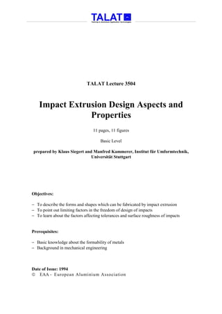
8. Reference Values for Determining the Allowable Tolerances for Simple Impacts
The correct choice of tolerances influences the economy of the process as well as the
operating life of the tools and is often the decisive criterion for determining whether the
part can be produced at all by impact extrusion. On the other hand, a judicious design is
an essential factor in determining whether the required tolerances can be adhered to.
Since the type and amount of tolerances depend on many factors, no general guidelines
and rules can be laid out for determining these. Reference values for determining the
tolerance as a function of dimension are shown in Figure 3504.02.03 for simple, axially
symmetrical impacts. In spite of this, it can be necessary in some cases to reach an
agreement with the manufacturer regarding allowable tolerances [5].
Reference Values for Determining the
Allowable Tolerances for Simple Impacts
Deviations in dimensions
Deviations in dimensions of wall thickness
0.4
0.4
outside diameters
[mm] [mm]
0.3 Deviations in dimensions
0.2 of base thickness
0.2 0.4
[mm]
0.1 0.2
0 20 40 60 80 100 0 0.4 0.8 1.2 1.6 2.0 0 20 40 60 80 100
Outside diameter, Da in mm Wall thickness, s, in mm Outside diameter, Da, in mm
H
Deviations in dimensions Axes displacement
± 0.5
of inside lengths [mm]
1.0 ± 0.4
[mm] ± 0.3
D
0.5 0.4 Flexure
± 0.2
[mm]
± 0.1 0.2
0 100 200 300 0 100 200 300 400 500 600 0 100 200 300 400
Inside lengths, Hi, in mm F = Wall thickness s [mm] x H [mm] Length H, in mm
Source: Aluminium-Zentrale Düsseldorf, Report 29
alu Reference Values for Determining the Allowable
Training in Aluminium Application Technologies Tolerances for Simple Impacts 3504.02.03
Figure 3504.02.04 explains the reasons which cause dimensional deviations to occur in
the impacts.
TALAT 3504 8
9. Causes of Tolerances During the
Impact Extrusion of Aluminium
! Inconsistency of material properties
! Inconsistency of heat-treatment and surface treatment
(lubrication)
! Precision with which semifabricates and slugs or blanks
are produced
! Precision of tool during manufacturing and assembly
! Operating condition and distortion of machine and tools
Source: VDI-Richtlinie 3138, part 1
alu Causes of Tolerances During the Impact
Training in Aluminium Application Technologies Extrusion of Aluminium 3504.02.04
Factors Affecting the Surface Roughness of Impacts
Normally, impacts have surfaces of high quality with practically no notches on the
surface, which could lead to stress concentrations, and a good resistance to wear. Since
the surface roughness depends on numerous factors, a certain amount of scatter of this
property is unavoidable [4], see Figure 3504.02.05.
Factors Affecting the Surface
Roughness of Impacts
! Surface quality produced with impact extrusion
combined with supplementary fabricating processes
(including dimensional variations of the preformed or raw parts)
! Surface quality or surface condition of tools
! Lubricants and methods of their application
! Deformation strain in connection with flow conditions
! Grain size in microstructure
Source: VDI-Richtlinie 3138, part 1
alu Factors Affecting the Surface Roughness
Training in Aluminium Application Technologies of Impacts 3504.02.05
Different values for peak-to-valley depths of roughness, Rt, are obtained in the impact
extrusion direction and transverse to it as well as on or under the phosphate coating or
TALAT 3504 9
10. lubricant layer. Figure 3504.02.06 shows reference values for a charge of approximately
10,000 impacts. For steel impacts, the whole range of roughness depths are valid. For
nonferrous metals, the lowest values for the depicted range can be generally attained.
The term "difficult to attain values" refers to the special surface finishing for the tool
parts subjected to wear as well as their repeated replacement [4].
Reference Values for Locally Attainable
Peak-to-Valley Depths of Roughness in Impacts
a without difficulties / b values difficult to attain
transverse to flow direction
20 a
Peak-to-valley depth
a
of roughness, Rt,
µm
a a b
10 a b
b b b
0
20
Peak-to-valley depth
a
of roughness, Rt,
a
in flow direction
µm
a b
a
10 a b
b b
b
0
Pb, Sn Ma 8 / Mbk 6, C 10, 16MnCr5, Ck 35, Ck 45, Cq 45, 18NiCrMo5,
Material Al99.5 Ck 10, Cq 10, C 15, Cq 35, 15 Cr 3, 34CrMo4, 100 Cr 3,
AlMgSi1 Ck 15, Cq 15 34 Cr 4, 25CrMo4 20MnCr5 100 Cr 6
Source: VDI-Tichtlinie 3138, part 1
alu Reference Values for Locally Attainable
Training in Aluminium Application Technologies Peak-to-Valley Depths of Roughness in Impacts 3504.02.06
TALAT 3504 10
11. 3504.03 Literature
[1] F. Ostermann: Technische Kaltfließpreßteile aus Aluminium. In seminar volume
"Gestalten und Fertigen von technischen Fließpreßteilen aus Aluminium", Institut für
Umformtechnik, Universität Stuttgart, 15.-16- June, 1992.
[2] D. Schlosser: Einflußgrößen auf das Fließpressen von Aluminium und
Aluminiumlegierungen und ihre Auswirkung auf die Weiter- und Fertigungsarbeitung
der fließgepreßten Rohteile. In seminar volume "Gestalten und Fertigen von technischen
Fließpreßteilen aus Aluminium", Institut für Umformtechnik, Universität Stuttgart, 15.-
16- June, 1992.
[3] D. Brix: Kaltfließpressen von Leichtmetall - Qualität und Wirtschaftlichkeit. Draht
(1975)5, p. 216 - 219.
[4] VDI-Richtlinie 3138: Kaltfließpressen von Stählen und Nichtmetallen, Grundlagen,
Blatt 1. Berlin: Beuth-Verlag 1970.
[5] Aluminium-Zentrale e.V., Report No. 29 "Aluminium für technische Fließpreßteile",
Dusseldorf, 1982.
3504.04 List of Figures
Figure No. Figure Title (Overhead)
3504.01.01 Form Examples of Cold Impact Extruded Products of Aluminium
3504.01.02 Design Characteristics of Impacts Made out of Aluminium
3504.01.03 Types of Wall Forms
3504.01.04 Types of Base Forms
3504.01.05 Design Errors
3504.02.01 Factors Affecting the Manufacturing Tolerances
3504.02.02 Production Tolerances
3504.02.03 Reference Values for Determining the Allowable Tolerances for Simple
Impacts
3504.02.04 Causes of Tolerances during the Impact Extrusion of Aluminium
3504.02.05 Factors Affecting the Surface Roughness of Impacts
3504.02.06 Reference Values for Locally Attainable Peak-to-Valley Depths of
Roughness in Impacts
TALAT 3504 11