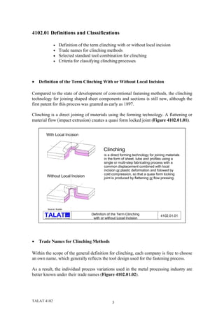
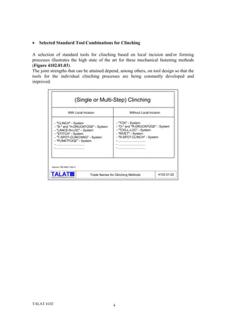
TALAT Lecture 4102


                                  Clinching
                                   13 pages, 14 figures

                                      Basic Level

      prepared by Lothar Budde, Universität-Gesamthochschule Paderborn


Objectives:

− to describe the detailed processes of single-step and multiple-step clinching

− to show the differences of the various clinching methods concerning the amount of
  shearing

− to illustrate the major differences in mechanical properties of clinch joints compared
  with resistance spot welds


Prerequisites:

− General mechanical engineering background

− TALAT Lecture 4101


Date of Issue: 1994
 EAA - European Aluminium Association
4102 Clinching


Table of Contents


4102 Clinching .............................................................................................................2
   4102.01 Definitions and Classifications................................................................. 3
       • Definition of the Term Clinching With or Without Local Incision ....................3
       • Trade Names for Clinching Methods...................................................................3
       • Selected Standard Tool Combinations for Clinching ..........................................4
       • Criteria for Classifying Clinching Processes .......................................................5
   4102.02 The Clinching Process .............................................................................. 6
       • Process Steps in Single-Step Clinching with Local Incision ...............................6
       • Process Steps During Two-Step or Multi-step Clinching with Local Incision...7
       • Geometry of a Clinched Joint Formed by Clinching With or Without Local
       Incision.....................................................................................................................8
       • A Comparison of the Properties of Clinched Joints and Spot Welded Joints.....9
       • Process Steps of a Single-Step Clinching Process without Local Incision (Die
       with Movable Parts).................................................................................................9
       • Process Steps of a Single-step Clinched Joint without Local Incision (Die
       without Movable Parts)..........................................................................................10
       • Formation of a Flat Clinch Element without Local Incision..............................11
       • Comparison of Clinch Elements with Varying Local Incisions and Formed Parts
          12
       • Holding and Stripping Systems for Clinching ...................................................12
   4102.03 Literature/References ............................................................................. 13
   4102.04 List of Figures............................................................................................ 14


TALAT 4102                                                         2
4102.01 Definitions and Classifications

                     •         Definition of the term clinching with or without local incision
                     •         Trade names for clinching methods
                     •         Selected standard tool combination for clinching
                     •         Criteria for classifying clinching processes


•   Definition of the Term Clinching With or Without Local Incision

Compared to the state of development of conventional fastening methods, the clinching
technology for joining shaped sheet components and sections is still new, although the
first patent for this process was granted as early as 1897.

Clinching is a direct joining of materials using the forming technology. A flattening or
material flow (impact extrusion) creates a quasi form locked joint (Figure 4102.01.01).


        With Local Incision


                                                               Clinching
                                                               is a direct forming technology for joining materials
                                                               in the form of sheet, tube and profiles using a
                                                               single or multi-step fabricating process with a
                                                               common displacement combined with local
                                                               incision or plastic deformation and folowed by
                                                               cold compression, so that a quasi form locking
          Without Local Incision                               joint is produced by flattening or flow pressing.


           Source: Budde

                                             alu       Definition of the Term Clinching               4102.01.01
      Training in Aluminium Application Technologies    with or without Local Incision


•   Trade Names for Clinching Methods

Within the scope of the general definition for clinching, each company is free to choose
an own name, which generally reflects the tool design used for the fastening process.

As a result, the individual process variations used in the metal processing industry are
better known under their trade names (Figure 4102.01.02).


TALAT 4102                                                          3
•   Selected Standard Tool Combinations for Clinching

A selection of standard tools for clinching based on local incision and/or forming
processes illustrates the high state of the art for these mechanical fastening methods
(Figure 4102.01.03).
The joint strengths that can be attained depend, among others, on tool design so that the
tools for the individual clinching processes are being constantly developed and
improved.


                                                           (Single or Multi-Step) Clinching

                                           With Local Incision                              Without Local Incision


                - "CLINCH" - System                                                 - "TOX" - System
                - "S-" and "H-DRUCKFÜGE" - System                                   - "O-" and "R-DRUCKFÜGE" - System
                - "LANCE-N-LOC" - System                                            - "TOG-L-LOC" - System
                - "STITCH" - System                                                 - "RIVET" - System
                - "T-SPOT-CLINCHING" - System                                       - "R-SPOT-CLINCH" - System
                - "PUNKTFÜGE" - System                                              - ...............................
                - ................................                                  - ...............................
                - ................................                                  - ...............................


           Source: DIN 8593, Part 5


                                                 alu
                                                                 Trade Names for Clinching Methods              4102.01.02
          Training in Aluminium Application Technologies


TALAT 4102                                                                      4
Clinch-Process                                 DRUCKFÜGE-Process                RIVET-Process           TOX-Process

                  Cutting Punch                                        Punch                     Forming Punch          Forming Punch


                                                                                                          O-Rings

                                                      Compressing               Cutting
                                                      Punch                     Laminae


                                                                                                              Wedging
                                                                                    Anvil                     Punch


                    Cutting Die                                     Spreading Die                  Form Die                Form Die
              Source: Budde

                                                      alu

              Training in Aluminium Application Technologies
                                                               Selected Standard Tool Combination for Clinching            4102.01.03


•   Criteria for Classifying Clinching Processes

Based on the DIN standard 8593, part 5, it is possible to characterise clinching either
according to the kinematics of the tool components (single or multi-step clinching) or
the shape of the joint itself (clinching with or without local incision, see also Figure
4102.01.04).


                                          Classifying the Clinching Process


                                                               According to the Kinematics of the Tool Parts
                                                                      In Single and Multi-Step Clinching


                                                               According to the Joining Element Form
                                                                       In Clinching with and without Local Incision


                                                alu
                                                                 Criteria for Classifying Clinching Processes                4102.01.04
       Training in Aluminium Application Technologies


TALAT 4102                                                                                  5
4102.02The Clinching Process

          •   Process steps in single-step clinching with local incision
          •   Process steps during two-step or multi-step clinching with local incision
          •   Geometry of a clinched joint formed by clinching with or without local
              incision
          •   A comparison of the properties of clinched joints and spot welded joints
          •   Process steps of a single-step clinching process without local incision (die
              with movable parts)
          •   Process steps of a single-step clinched joint without local incision (die
              without movable parts)
          •   Formation of a flat clinch element without local incision
          •   Process steps of a multi-step clinched joint without local incision
          •   Comparison of clinch elements with varying local incisions and formed
              parts
          •   Holding and stripping systems for clinching


•   Process Steps in Single-Step Clinching with Local Incision

Clinching with local incision creates an undetachable (permanent) joint under the
combined action of shear and penetration processes, in which the penetration and
incision limit the joint region, and a cold compression process, in which the sheet
material pushed out of the sheet plane is compressed and flattened in such a manner that
a quasi form locked joint is created.

The single-step clinching process derives its name from the fact that the joint is created
during an uninterrupted stroke of a single tool component (Figure 4102.02.01).


TALAT 4102                                   6
Punch


                                                                                               Joined parts


                                                                                               Die


       Source: Budde

                                            alu
                                                      Process Steps in Single-Step Clinching
     Training in Aluminium Application Technologies            with Local Incision              4102.02.01


•   Process Steps During Two-Step or Multi-step Clinching with Local Incision

The clinch joining element of a two-step or multi-step clinch process with local incision
is created under the action of successive motions of the tool components .

Although the multi-step clinching process works, unlike the single-step clinching
process, with a single tool combination for the corresponding joint geometry, this
process, because of its more complicated alignment technique, has not been very
successful till now (Figure 4102.02.02).


TALAT 4102                                                              7
Cutting Die

           Compressing
           Punch

            Parts to be
            joined

                                Cutting
                                Punch


          Source: Budde

                                                  alu       Process Steps during Two-Step or Multi-Step clinching   4102.02.02
           Training in Aluminium Application Technologies                    with Local Incision


•   Geometry of a Clinched Joint Formed by Clinching With or Without Local
    Incision

In recent years, a large number of fastening elements, based on the principles of the
clinched joint element, have been developed.

Characteristic for all these recent developments is an increase in the joint strength
resulting from the enlarged shear area as well as from the reduction of the locally
incised part which is replaced by a corresponding increase in the plastically formed part
(see Figure 4102.02.03).

                                                                   increasing th
                                                                                   e sheared a
                                                                                               rea


                                                   decreasing th
                                                                         e sheared ar
                                                                                         ea


        Source: Budde

                                                alu           Geometry of a Clinched Joint Formed by Clinching      4102.02.03
        Training in Aluminium Application Technologies                 with or without Local Incision


TALAT 4102                                                                           8
•   A Comparison of the Properties of Clinched Joints and Spot Welded Joints

Results of experiments with single-element clinch fastenings with various locally
incised and formed parts as well as various shear areas demonstrate that under quasi
static and dynamic impact loadings, these joints do not attain the strength of a single
spot welded joint (see Figure 4102.02.04). This result is also valid for clinch joints with
enlarged clinched elements.

On the other hand, in the case of dynamic loading, the strength of clinched joints is
superior to that of spot welded joints, especially if the local incision is reduced in favour
of the formed part, thereby reducing the notch action.


           1                   SW                         2 CL with
                                                            Local Incision 3
                                                                                                           CL with Reduced                     4 CL without
                                                                                                           Local Incision                          Local Incision


                              %                           AlMg5Mn                             %                                           %
                                                          s = 1.25 mm
                         180                                                            180                                           180
                                                                        Reapted Cycle Force
          Fracture Strength


                         160                                                            160                                           160
                                                                                                                                                        V = 5.3 m/s
                                                                                                                          Fracture Work


                         120                      V=10 mm/ min                          120                                           120

                              80                                                              80                R=0.0                     80
                                                                                                                 f=80Hz
                              40                                                              40                                          40
                                   1       2          3     4                                      1   2    3    4                             1    2      3     4
                              0                                                               0                                           0
     Source: Budde

                                                           A Comparison of the Properties of Clinched
                                            alu
                                                                                                                                                         4102.02.04
     Training in Aluminium Application Technologies            Joints and Spot Welded Joints


•   Process Steps of a Single-Step Clinching Process without Local Incision (Die
    with Movable Parts)

In the clinching process without local incision, a combined penetration and clinch
operation (whereby the fastened region is limited by the penetration) is followed by a
cold compression process (whereby the displaced volume of material is flattened by
compression) leading to a quasi form locked joint formed by material flow (impact
extrusion) (see Figure 4102.02.05).

The displaced material of the clinch joint, relevant for the fastening strength, is formed
by the varying flow characteristics of the material on the die and punch sides.


TALAT 4102                                                                                             9
Parts to be
              joined


              Die with
              Movable
              Parts

                                                                                                                            Rubber
                                                                                                                            Ring


                Source: Budde

                                                     alu           Process Steps of a Single-Step Clinching Process
              Training in Aluminium Application Technologies        without Local Incision (Die with Movable Parts)      4102.02.05


•   Process Steps of a Single-step Clinched Joint without Local Incision (Die
    without Movable Parts)

Tool systems with and without moving parts have been designed for the single-step
clinching process without local incision .

During the single-step clinching process with movable die parts, the different flow
characteristics of the material of the parts to be joint is caused by a yielding of the
sheets. On the other hand, in the single-step clinching process without movable parts, a
grooved ring in the die forces the displaced material of the sheets to flow differently
(Figure 4102.02.06).

The advantage of the die without moving parts lies in the absence of wear of the
components. The disadvantage is that oiled aluminium sheets can lead to the formation
of a "hydrostatic cushion" in the closed die, leading eventually to the destruction of the
die.


                                                                                                                         Punch


                                                                                                                         Joined
                                                                                                                         Parts


                                                                                                                      Die without
                                                                                                                      Moveable Parts


                   Source: Budde

                                                           alu
                                                                      Process Steps of a Single-Step Clinched Joint
                  Training in Aluminium Application Technologies   Without Local Incision (Die Without Moveable Parts)   4102.02.06


TALAT 4102                                                                                10
•   Formation of a Flat Clinch Element without Local Incision

New variations of the clinching process which overcome the process limitations of the
single-step and multi-step clinching process with and without local incision, are being
developed constantly. The basic principle, however, remains unchanged.
Thus, it is possible to flatten the typical edged form of the clinch element without local
incision in a second operation, so that this side can be used for the visible surface
(Figure 4102.02.07).

                              Starting Condition                            Intermediate Stage             End Condition

                                           Round Form                                                       Flat Form


                  Fixing
                  Punch


                Joined
                Parts


                Counter
                Punch


               Source: Budde

                                                       alu
                                                                     Formation of a Flat Clinch Element
                Training in Aluminium Application Technologies            without Local Incision                  4102.02.07


Similar to clinching with local incision, it is possible, in a two-step or multi-step
process, to produce a clinch element without local incision (Figure 4102.02.08).

The two-step or multi-step process for clinching uses about 20 % less energy than that
required for single-step clinching, due to the fact that the penetration and compression
(flattening) steps of the former occur in consecutive steps.


              Displacing
              Punch


              Parts to be
              joined


             Displacing
             Die


             Compressing
             Punch

              Source: Budde

                                                                 Process Steps of A Multi-Step Clinched Joint
                                                      alu

                                                                            without Local Incision                4102.02.08
              Training in Aluminium Application Technologies


TALAT 4102                                                                           11
•   Comparison of Clinch Elements with Varying Local Incisions and Formed
    Parts

As illustrated in the comparison of clinch elements with varying local incisions and
formed parts, reducing the local incision part in favour of the formed part is coupled
with a reduction of notch effect - i.e. primarily an improved behaviour of the joint under
dynamic loading - as well as reduced chip production. At the same time, however, this
leads to the need for tools able to meet the added requirements.


             Clinching                       Tool         Chip    Joining   Infuence of   Local     Formed    Geometric
                Tool                        Control    Production Element   Joining Part Incision    Part      Notch
                                                                              Surface                          Effect


      Source: Budde
                                                        Comparison of Clinch Elements with Varying
                                             alu
                                                                                                             4102.02.09
      Training in Aluminium Application Technologies        Local Incisions and Formed Parts


This means that reducing the incision part amounts to an increased effort in aligning
punch and die (Figure 4102.02.09).

In order to align clinching tools accurately for joints without local incision, special
clamps with double-C frames have been developed, making the use of clinching robots
possible.


•   Holding and Stripping Systems for Clinching

A faultless holding system, a prerequisite for producing high quality clinching, must
clamp the aligned parts, so that the material flow during the clinching process does not
cause a movement of the position of joining groups relative to each other.

Appropriate holding systems can be used to clamp the joining parts as well as strip the
finished part from the dies.


TALAT 4102                                                                  12
Just as in the case of clinching, holding systems must also be adapted for use in punch
riveting (Figure 4102.02.10).


                                                                   Single-Step Clinching
                                                                    with Local Incision


                                                      Single-Step Clinching
                                                      without Local Incision


                                            alu
                                                       Holding and Stripping Systems for Clinching   4102.02.10
     Training in Aluminium Application Technologies


4102.03Literature/References

1. Budde, L. Untersuchungen zur Kombination quasi-formschlüssiger                                                 und
   stoffschlüssiger Verbindungsverfahren. Dissertation Uni-GH-Paderborn, 1989
2. Liebig, H.P. Nieten und Durchsetzfügen. Blech Rohre Profile 39 (1992) 3, 220-221
3. Boldt,     M.     Mechanisches     Verhalten   von    Durchsetzfüge-   und
   Punktschweißverbindungen bei quasistatischer und dynamischer Beanspruchung.
   Dissertation Uni-GH-Paderborn, 1992
4. Steimmel, F. Einfluß der Blechoberflächen auf das Festigkeitsverhalten. Bänder
   Bleche Rohre 31 (1990) 11, 33-36
5. Schmid, G. Methoden der Qualitätssicherung beim Durchsetzfügen. Bänder Bleche
   Rohre 32 (1991) 61-64
6. Schröder, D. Neue Verbindungstechniken für Aluminiumwerkstoffe. Bänder
   Bleche Rohre 32 (1991) 5, 83-87
7. Beyer, R. Kostengünstig und technisch interessant - Druckfügen. Industrie-Anzeiger
   110 (1988) Nr. 16, 26-29
8. Reuter, H. Erfahrungen mit dem Durchsetzfügen in der Automobilindustrie.
   Tagungsband “Umformtechnisches Fügen von Blech“, Chemnitz 1990
9. Bober, J. und Liebig, H.P. Prozeßanalyse beim Druckfügen. Bänder Bleche Rohre
   31 (1990) 10, 143-146


TALAT 4102                                                                 13
4102.04 List of Figures


Figure No.   Figure Title (Overhead)

4102.01.01   Definition of the Term Clinching with or without Local Incision
4102.01.02   Trade Names for Clinching Methods
4102.01.03   Selected Standard Tool Combination for Clinching
4102.01.04   Criteria for Classifying Clinching Processes

4102.02.01   Process Steps in Single-Step Clinching with Local Incision
4102.02.02   Process Steps during Two-Step or Multi-Step Clinching with Local Incision
4102.02.03   Geometry of a Clinched Joint Formed by Clinching with or without Local
             Incision
4102.02.04   A Comparison of the Properties of Clinched Joints and Spot Welded Joints
4102.02.05   Process Steps of a Single-Step Clinching Process without Local Incision (Die
             with Movable Parts)
4102.02.06   Process Steps of a Single-Step Clinched Joint without Local Incision (Die
             without Movable Parts)
4102.02.07   Formation of a Flat Clinch Element without Local Incision
4102.02.08   Process Steps of a Multi-Step Clinched Joint without Local Incision
4102.02.09   Comparison of Clinch Elements with Varying Local Incisions and Formed
             Parts
4102.02.10   Holding and Stripping Systems for Clinching


TALAT 4102                                14

TALAT Lecture 4102: Clinching

  • 1.
    TALAT Lecture 4102 Clinching 13 pages, 14 figures Basic Level prepared by Lothar Budde, Universität-Gesamthochschule Paderborn Objectives: − to describe the detailed processes of single-step and multiple-step clinching − to show the differences of the various clinching methods concerning the amount of shearing − to illustrate the major differences in mechanical properties of clinch joints compared with resistance spot welds Prerequisites: − General mechanical engineering background − TALAT Lecture 4101 Date of Issue: 1994  EAA - European Aluminium Association
  • 2.
    4102 Clinching Table ofContents 4102 Clinching .............................................................................................................2 4102.01 Definitions and Classifications................................................................. 3 • Definition of the Term Clinching With or Without Local Incision ....................3 • Trade Names for Clinching Methods...................................................................3 • Selected Standard Tool Combinations for Clinching ..........................................4 • Criteria for Classifying Clinching Processes .......................................................5 4102.02 The Clinching Process .............................................................................. 6 • Process Steps in Single-Step Clinching with Local Incision ...............................6 • Process Steps During Two-Step or Multi-step Clinching with Local Incision...7 • Geometry of a Clinched Joint Formed by Clinching With or Without Local Incision.....................................................................................................................8 • A Comparison of the Properties of Clinched Joints and Spot Welded Joints.....9 • Process Steps of a Single-Step Clinching Process without Local Incision (Die with Movable Parts).................................................................................................9 • Process Steps of a Single-step Clinched Joint without Local Incision (Die without Movable Parts)..........................................................................................10 • Formation of a Flat Clinch Element without Local Incision..............................11 • Comparison of Clinch Elements with Varying Local Incisions and Formed Parts 12 • Holding and Stripping Systems for Clinching ...................................................12 4102.03 Literature/References ............................................................................. 13 4102.04 List of Figures............................................................................................ 14 TALAT 4102 2
  • 3.
    4102.01 Definitions andClassifications • Definition of the term clinching with or without local incision • Trade names for clinching methods • Selected standard tool combination for clinching • Criteria for classifying clinching processes • Definition of the Term Clinching With or Without Local Incision Compared to the state of development of conventional fastening methods, the clinching technology for joining shaped sheet components and sections is still new, although the first patent for this process was granted as early as 1897. Clinching is a direct joining of materials using the forming technology. A flattening or material flow (impact extrusion) creates a quasi form locked joint (Figure 4102.01.01). With Local Incision Clinching is a direct forming technology for joining materials in the form of sheet, tube and profiles using a single or multi-step fabricating process with a common displacement combined with local incision or plastic deformation and folowed by cold compression, so that a quasi form locking Without Local Incision joint is produced by flattening or flow pressing. Source: Budde alu Definition of the Term Clinching 4102.01.01 Training in Aluminium Application Technologies with or without Local Incision • Trade Names for Clinching Methods Within the scope of the general definition for clinching, each company is free to choose an own name, which generally reflects the tool design used for the fastening process. As a result, the individual process variations used in the metal processing industry are better known under their trade names (Figure 4102.01.02). TALAT 4102 3
  • 4.
    Selected Standard Tool Combinations for Clinching A selection of standard tools for clinching based on local incision and/or forming processes illustrates the high state of the art for these mechanical fastening methods (Figure 4102.01.03). The joint strengths that can be attained depend, among others, on tool design so that the tools for the individual clinching processes are being constantly developed and improved. (Single or Multi-Step) Clinching With Local Incision Without Local Incision - "CLINCH" - System - "TOX" - System - "S-" and "H-DRUCKFÜGE" - System - "O-" and "R-DRUCKFÜGE" - System - "LANCE-N-LOC" - System - "TOG-L-LOC" - System - "STITCH" - System - "RIVET" - System - "T-SPOT-CLINCHING" - System - "R-SPOT-CLINCH" - System - "PUNKTFÜGE" - System - ............................... - ................................ - ............................... - ................................ - ............................... Source: DIN 8593, Part 5 alu Trade Names for Clinching Methods 4102.01.02 Training in Aluminium Application Technologies TALAT 4102 4
  • 5.
    Clinch-Process DRUCKFÜGE-Process RIVET-Process TOX-Process Cutting Punch Punch Forming Punch Forming Punch O-Rings Compressing Cutting Punch Laminae Wedging Anvil Punch Cutting Die Spreading Die Form Die Form Die Source: Budde alu Training in Aluminium Application Technologies Selected Standard Tool Combination for Clinching 4102.01.03 • Criteria for Classifying Clinching Processes Based on the DIN standard 8593, part 5, it is possible to characterise clinching either according to the kinematics of the tool components (single or multi-step clinching) or the shape of the joint itself (clinching with or without local incision, see also Figure 4102.01.04). Classifying the Clinching Process According to the Kinematics of the Tool Parts In Single and Multi-Step Clinching According to the Joining Element Form In Clinching with and without Local Incision alu Criteria for Classifying Clinching Processes 4102.01.04 Training in Aluminium Application Technologies TALAT 4102 5
  • 6.
    4102.02The Clinching Process • Process steps in single-step clinching with local incision • Process steps during two-step or multi-step clinching with local incision • Geometry of a clinched joint formed by clinching with or without local incision • A comparison of the properties of clinched joints and spot welded joints • Process steps of a single-step clinching process without local incision (die with movable parts) • Process steps of a single-step clinched joint without local incision (die without movable parts) • Formation of a flat clinch element without local incision • Process steps of a multi-step clinched joint without local incision • Comparison of clinch elements with varying local incisions and formed parts • Holding and stripping systems for clinching • Process Steps in Single-Step Clinching with Local Incision Clinching with local incision creates an undetachable (permanent) joint under the combined action of shear and penetration processes, in which the penetration and incision limit the joint region, and a cold compression process, in which the sheet material pushed out of the sheet plane is compressed and flattened in such a manner that a quasi form locked joint is created. The single-step clinching process derives its name from the fact that the joint is created during an uninterrupted stroke of a single tool component (Figure 4102.02.01). TALAT 4102 6
  • 7.
    Punch Joined parts Die Source: Budde alu Process Steps in Single-Step Clinching Training in Aluminium Application Technologies with Local Incision 4102.02.01 • Process Steps During Two-Step or Multi-step Clinching with Local Incision The clinch joining element of a two-step or multi-step clinch process with local incision is created under the action of successive motions of the tool components . Although the multi-step clinching process works, unlike the single-step clinching process, with a single tool combination for the corresponding joint geometry, this process, because of its more complicated alignment technique, has not been very successful till now (Figure 4102.02.02). TALAT 4102 7
  • 8.
    Cutting Die Compressing Punch Parts to be joined Cutting Punch Source: Budde alu Process Steps during Two-Step or Multi-Step clinching 4102.02.02 Training in Aluminium Application Technologies with Local Incision • Geometry of a Clinched Joint Formed by Clinching With or Without Local Incision In recent years, a large number of fastening elements, based on the principles of the clinched joint element, have been developed. Characteristic for all these recent developments is an increase in the joint strength resulting from the enlarged shear area as well as from the reduction of the locally incised part which is replaced by a corresponding increase in the plastically formed part (see Figure 4102.02.03). increasing th e sheared a rea decreasing th e sheared ar ea Source: Budde alu Geometry of a Clinched Joint Formed by Clinching 4102.02.03 Training in Aluminium Application Technologies with or without Local Incision TALAT 4102 8
  • 9.
    A Comparison of the Properties of Clinched Joints and Spot Welded Joints Results of experiments with single-element clinch fastenings with various locally incised and formed parts as well as various shear areas demonstrate that under quasi static and dynamic impact loadings, these joints do not attain the strength of a single spot welded joint (see Figure 4102.02.04). This result is also valid for clinch joints with enlarged clinched elements. On the other hand, in the case of dynamic loading, the strength of clinched joints is superior to that of spot welded joints, especially if the local incision is reduced in favour of the formed part, thereby reducing the notch action. 1 SW 2 CL with Local Incision 3 CL with Reduced 4 CL without Local Incision Local Incision % AlMg5Mn % % s = 1.25 mm 180 180 180 Reapted Cycle Force Fracture Strength 160 160 160 V = 5.3 m/s Fracture Work 120 V=10 mm/ min 120 120 80 80 R=0.0 80 f=80Hz 40 40 40 1 2 3 4 1 2 3 4 1 2 3 4 0 0 0 Source: Budde A Comparison of the Properties of Clinched alu 4102.02.04 Training in Aluminium Application Technologies Joints and Spot Welded Joints • Process Steps of a Single-Step Clinching Process without Local Incision (Die with Movable Parts) In the clinching process without local incision, a combined penetration and clinch operation (whereby the fastened region is limited by the penetration) is followed by a cold compression process (whereby the displaced volume of material is flattened by compression) leading to a quasi form locked joint formed by material flow (impact extrusion) (see Figure 4102.02.05). The displaced material of the clinch joint, relevant for the fastening strength, is formed by the varying flow characteristics of the material on the die and punch sides. TALAT 4102 9
  • 10.
    Parts to be joined Die with Movable Parts Rubber Ring Source: Budde alu Process Steps of a Single-Step Clinching Process Training in Aluminium Application Technologies without Local Incision (Die with Movable Parts) 4102.02.05 • Process Steps of a Single-step Clinched Joint without Local Incision (Die without Movable Parts) Tool systems with and without moving parts have been designed for the single-step clinching process without local incision . During the single-step clinching process with movable die parts, the different flow characteristics of the material of the parts to be joint is caused by a yielding of the sheets. On the other hand, in the single-step clinching process without movable parts, a grooved ring in the die forces the displaced material of the sheets to flow differently (Figure 4102.02.06). The advantage of the die without moving parts lies in the absence of wear of the components. The disadvantage is that oiled aluminium sheets can lead to the formation of a "hydrostatic cushion" in the closed die, leading eventually to the destruction of the die. Punch Joined Parts Die without Moveable Parts Source: Budde alu Process Steps of a Single-Step Clinched Joint Training in Aluminium Application Technologies Without Local Incision (Die Without Moveable Parts) 4102.02.06 TALAT 4102 10
  • 11.
    Formation of a Flat Clinch Element without Local Incision New variations of the clinching process which overcome the process limitations of the single-step and multi-step clinching process with and without local incision, are being developed constantly. The basic principle, however, remains unchanged. Thus, it is possible to flatten the typical edged form of the clinch element without local incision in a second operation, so that this side can be used for the visible surface (Figure 4102.02.07). Starting Condition Intermediate Stage End Condition Round Form Flat Form Fixing Punch Joined Parts Counter Punch Source: Budde alu Formation of a Flat Clinch Element Training in Aluminium Application Technologies without Local Incision 4102.02.07 Similar to clinching with local incision, it is possible, in a two-step or multi-step process, to produce a clinch element without local incision (Figure 4102.02.08). The two-step or multi-step process for clinching uses about 20 % less energy than that required for single-step clinching, due to the fact that the penetration and compression (flattening) steps of the former occur in consecutive steps. Displacing Punch Parts to be joined Displacing Die Compressing Punch Source: Budde Process Steps of A Multi-Step Clinched Joint alu without Local Incision 4102.02.08 Training in Aluminium Application Technologies TALAT 4102 11
  • 12.
    Comparison of Clinch Elements with Varying Local Incisions and Formed Parts As illustrated in the comparison of clinch elements with varying local incisions and formed parts, reducing the local incision part in favour of the formed part is coupled with a reduction of notch effect - i.e. primarily an improved behaviour of the joint under dynamic loading - as well as reduced chip production. At the same time, however, this leads to the need for tools able to meet the added requirements. Clinching Tool Chip Joining Infuence of Local Formed Geometric Tool Control Production Element Joining Part Incision Part Notch Surface Effect Source: Budde Comparison of Clinch Elements with Varying alu 4102.02.09 Training in Aluminium Application Technologies Local Incisions and Formed Parts This means that reducing the incision part amounts to an increased effort in aligning punch and die (Figure 4102.02.09). In order to align clinching tools accurately for joints without local incision, special clamps with double-C frames have been developed, making the use of clinching robots possible. • Holding and Stripping Systems for Clinching A faultless holding system, a prerequisite for producing high quality clinching, must clamp the aligned parts, so that the material flow during the clinching process does not cause a movement of the position of joining groups relative to each other. Appropriate holding systems can be used to clamp the joining parts as well as strip the finished part from the dies. TALAT 4102 12
  • 13.
    Just as inthe case of clinching, holding systems must also be adapted for use in punch riveting (Figure 4102.02.10). Single-Step Clinching with Local Incision Single-Step Clinching without Local Incision alu Holding and Stripping Systems for Clinching 4102.02.10 Training in Aluminium Application Technologies 4102.03Literature/References 1. Budde, L. Untersuchungen zur Kombination quasi-formschlüssiger und stoffschlüssiger Verbindungsverfahren. Dissertation Uni-GH-Paderborn, 1989 2. Liebig, H.P. Nieten und Durchsetzfügen. Blech Rohre Profile 39 (1992) 3, 220-221 3. Boldt, M. Mechanisches Verhalten von Durchsetzfüge- und Punktschweißverbindungen bei quasistatischer und dynamischer Beanspruchung. Dissertation Uni-GH-Paderborn, 1992 4. Steimmel, F. Einfluß der Blechoberflächen auf das Festigkeitsverhalten. Bänder Bleche Rohre 31 (1990) 11, 33-36 5. Schmid, G. Methoden der Qualitätssicherung beim Durchsetzfügen. Bänder Bleche Rohre 32 (1991) 61-64 6. Schröder, D. Neue Verbindungstechniken für Aluminiumwerkstoffe. Bänder Bleche Rohre 32 (1991) 5, 83-87 7. Beyer, R. Kostengünstig und technisch interessant - Druckfügen. Industrie-Anzeiger 110 (1988) Nr. 16, 26-29 8. Reuter, H. Erfahrungen mit dem Durchsetzfügen in der Automobilindustrie. Tagungsband “Umformtechnisches Fügen von Blech“, Chemnitz 1990 9. Bober, J. und Liebig, H.P. Prozeßanalyse beim Druckfügen. Bänder Bleche Rohre 31 (1990) 10, 143-146 TALAT 4102 13
  • 14.
    4102.04 List ofFigures Figure No. Figure Title (Overhead) 4102.01.01 Definition of the Term Clinching with or without Local Incision 4102.01.02 Trade Names for Clinching Methods 4102.01.03 Selected Standard Tool Combination for Clinching 4102.01.04 Criteria for Classifying Clinching Processes 4102.02.01 Process Steps in Single-Step Clinching with Local Incision 4102.02.02 Process Steps during Two-Step or Multi-Step Clinching with Local Incision 4102.02.03 Geometry of a Clinched Joint Formed by Clinching with or without Local Incision 4102.02.04 A Comparison of the Properties of Clinched Joints and Spot Welded Joints 4102.02.05 Process Steps of a Single-Step Clinching Process without Local Incision (Die with Movable Parts) 4102.02.06 Process Steps of a Single-Step Clinched Joint without Local Incision (Die without Movable Parts) 4102.02.07 Formation of a Flat Clinch Element without Local Incision 4102.02.08 Process Steps of a Multi-Step Clinched Joint without Local Incision 4102.02.09 Comparison of Clinch Elements with Varying Local Incisions and Formed Parts 4102.02.10 Holding and Stripping Systems for Clinching TALAT 4102 14