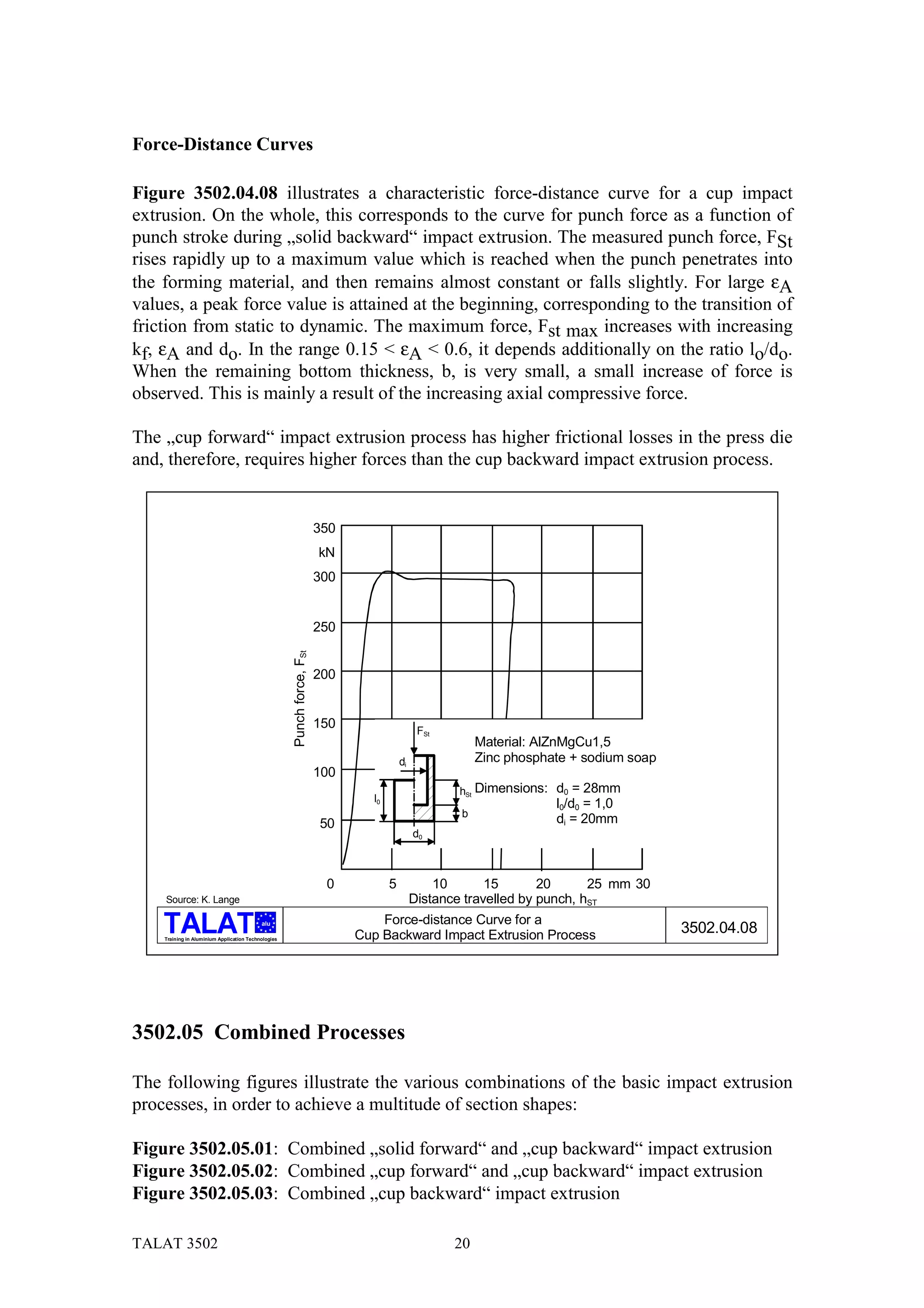
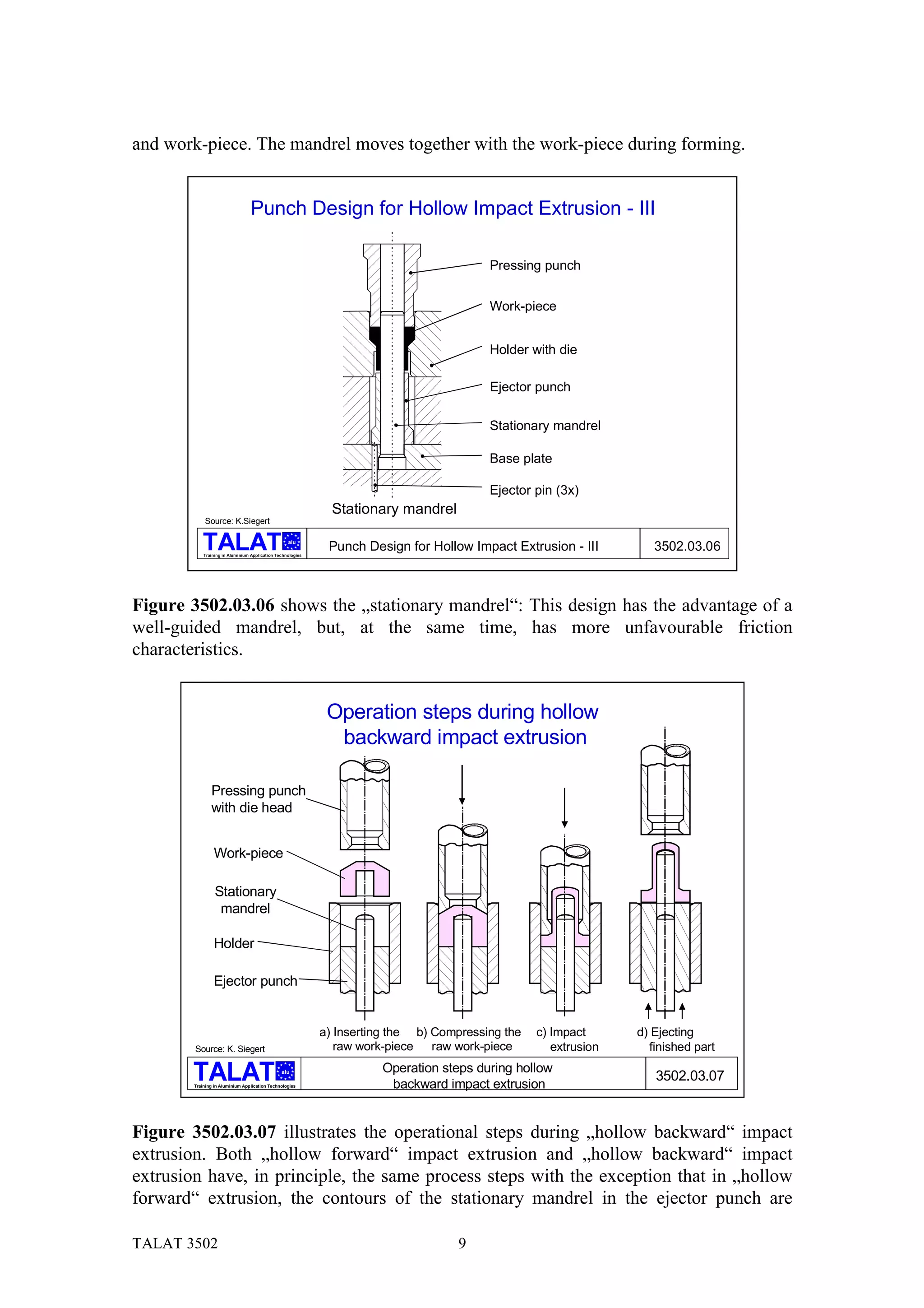
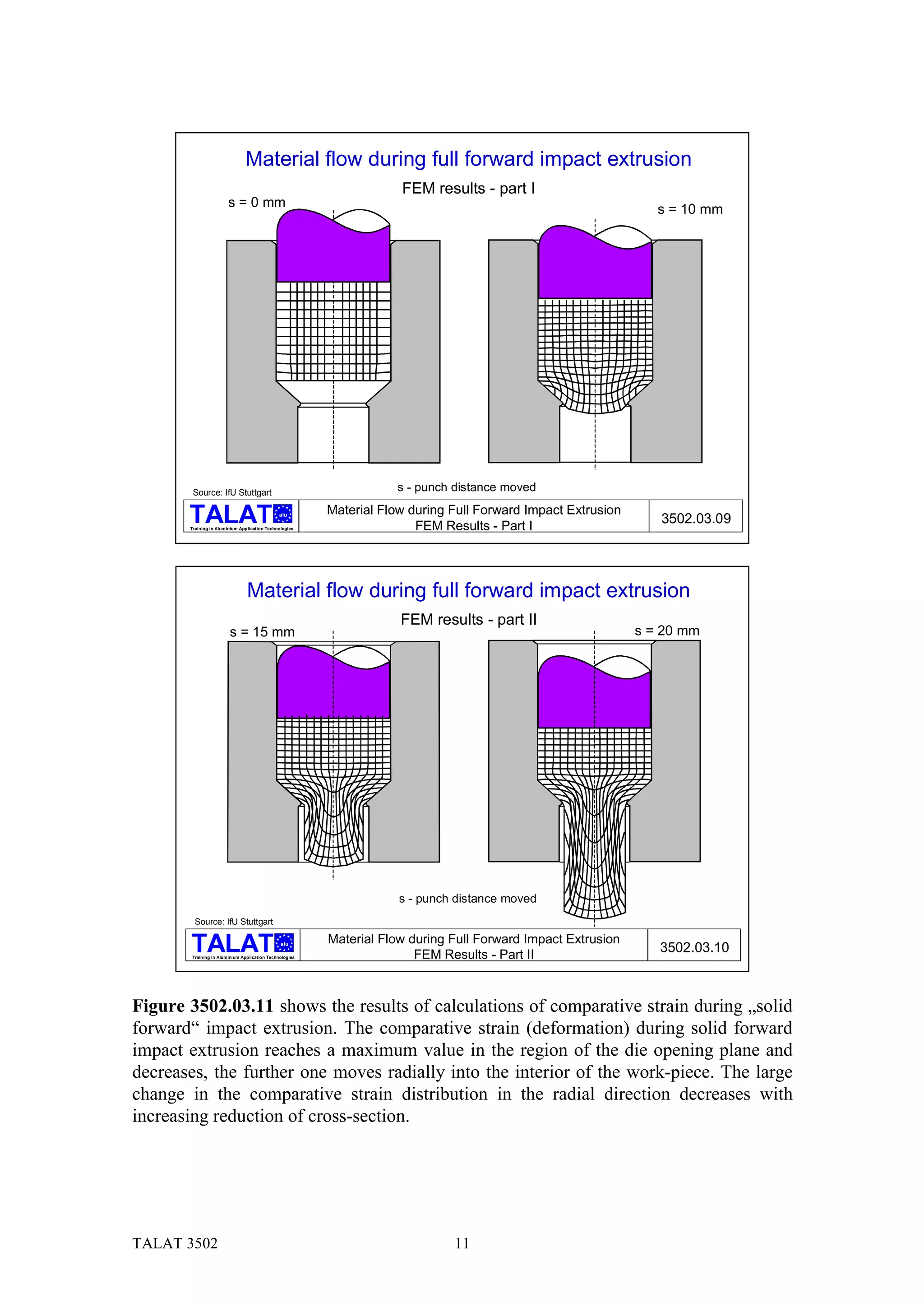
The document provides information on impact extrusion processes, including definitions, classifications, process steps, and material flow and deformation characteristics. Impact extrusion involves pressing a workpiece through a die opening using a punch. There are different classifications based on tool type, material flow direction, workpiece geometry, and temperature. Key process variations include solid and hollow, forward and backward extrusion. Material flow is initially non-stationary but transitions to quasi-stationary. Strain is highest near the die opening and decreases radially. Punch and die designs impact stresses and mandrel movement.
The document discusses the process of extrusion. It begins with an introduction to extrusion, defining it as reducing the cross-section of metal by forcing it to flow through a die under high pressure. It then covers the basic extrusion process using diagrams. The document goes on to classify extrusion processes and describe various types like direct/indirect, hot/cold, lateral, and hydrostatic extrusion. It also covers die design, defects, variables that affect extrusion, and applications of extrusion.
TALAT Lecture 3505: Tools for Impact ExtrusionCORE-Materials
This lecture provides knowledge about design philosophy and tool materials for impact tools, which are a cost factor and eminently important for successful impact extrusion. Basic knowledge about the formability of metals and background in mechanical engineering is assumed.
Okay, here are the steps:
1) UTS of 5052-O aluminum = 280 MPa
2) Thickness, t = 1.8 mm
3) Cutting edge length, L = πD = π * 25 mm = 78.5 mm
4) Using the empirical formula:
Fmax = 7.0 * UTS * t * L
= 7.0 * 280 * 1.8 * 78.5
= 3,400 N
So the estimated maximum punch force required is 3,400 Newtons.
This Presentation covers the basic concepts of Hot cracks and cold cracks in welding. For more information, please refer the books mentioned in the references slide.... Thank you
The document discusses various sheet metal processes including bending, shearing, staking, and stamping. It provides details on:
- How bending changes the shape of metal by plastic deformation within the material's yield strength. Press brakes are commonly used and allow a variety of shapes.
- Shearing is used to cut sheet metal to size from stock. It produces a burr that can be minimized to less than 10% of material thickness.
- Staking is used to fasten sheet metal by squeezing a protrusion into a hole and deforming it to lock the parts together.
- Stamping operations include blanking, piercing, forming, and drawing using dedicated tooling. It can
It is a near net shape process in which casting and forging is done in single step.
It is Referred by many names such as “squeeze casting” , “pressure infiltration”, “liquid metal forging”, “extrusion casting”, “liquid pressing'', “pressure crystallization”.
1) The document discusses design considerations for cast iron components, including keeping stressed areas in compression, rounding external corners, avoiding abrupt changes in cross-section thickness, and avoiding thin sections.
2) It recommends consulting the foundryman and patternmaker when designing castings and provides general principles such as keeping sections uniform, avoiding metal concentration at junctions, and using draft angles on patterns.
3) Some ways to improve casting strength are inserting studs, using cored holes, and providing minimum section thicknesses depending on the casting process.
The document discusses various aspects of metal forming processes including strain hardening, work hardening, annealing, cold working, hot working, and the effects of temperature and strain rate on formability.
Some key points include: Strain hardening occurs during metal forming at lower temperatures and increases flow stress. Work hardening is caused by an increase in dislocation density during plastic deformation. Annealing heat treats cold worked metals to restore ductility by reducing dislocation density. Cold working is done below the recrystallization temperature and causes strain hardening, while hot working allows recrystallization during forming. Temperature and strain rate impact formability, with higher temperatures and lower strain rates generally improving formability.
The document provides information about tool wear and tool life in machining processes. It discusses how tool wear occurs due to forces, temperature, and sliding action during cutting. The three main types of tool wear are flank wear, crater wear, and chipping. Flank wear is caused by abrasion from hard particles in the workpiece while crater wear results from high temperatures and diffusion at the tool-chip interface. Maintaining optimal cutting conditions and tool geometry can increase tool life. The document also covers tool materials, machinability factors, cutting fluids, machining forces, and lathe operations such as turning, facing, and threading.
Common defects in castings include misruns caused by insufficient fluidity, pouring at too low a temperature, too slow pouring, or thin cross-sections. Cold shuts occur when two portions of metal fuse together incompletely due to premature freezing. Shrinkage cavities form from solidification shrinkage restricting the last metal to freeze, often near the top of the casting. Microporosity consists of small voids from localized shrinkage in alloy dendrites. Hot tearing occurs when a casting is restrained from contracting in an unyielding mold during solidification.
Rolling is a metal forming process where metal stock is passed through one or more pairs of rolls to reduce the thickness and increase the length. There are two main types:
1) Hot rolling is performed above the metal's recrystallization temperature for lower pressure and improved ductility. It produces coarse grains and no residual stresses.
2) Cold rolling is performed below the recrystallization temperature, requiring higher pressures but improving dimensions, finish and strength through residual stresses and elongated grains.
Rolling mills are classified by the number of rolls used, including two-high, three-high, four-high and cluster/sendzimir mills. Continuous mills use multiple stands to continuously roll sheet metal.
Introduction to Manufacturing Processes and their Applications (Casting, Forging, Sheet metal working and Metal joining processes), Description of Casting process: Sand casting(Cope&Drag). Sheet metal Forming,(shearing, bending, drawing), Forging (Hot working and cold working comparison) ,Electric Arc welding, Comparison of Welding, Soldering, Brazing
This document discusses deep drawing, a sheet metal forming process where a punch is used to push a flat sheet into a die cavity. It describes the typical tool setup, components made via deep drawing like cups and conical shapes, and calculations for blank diameter. Stress patterns in different regions during drawing are explained. Factors affecting drawability and defects in formed components like wrinkling and bottom fracture are also summarized. Formulas for total punch force and drawability ratio are provided. Methods to improve drawability like redrawing and controlling texture are outlined.
The document discusses various joining processes including welding, brazing, and soldering. It describes different welding techniques like gas welding, arc welding, resistance welding, and special processes like laser beam and electron beam welding. It also covers brazing and soldering methods, the equipment involved, filler materials and fluxes used for different processes.
The document discusses various bulk metal forming processes including rolling, forging, extrusion, and wire/bar drawing. It provides details on:
- Rolling processes like flat rolling and shape rolling and the equipment used.
- Forging processes like open-die, impression-die, and flashless forging. Products include crankshafts and gears.
- Extrusion processes like direct and indirect extrusion which produce long, uniform cross-section parts.
- Wire and bar drawing which reduces cross-section by pulling metal through a die, similar to extrusion.
This document provides an overview of sheet metal forming processes. It discusses that sheet metal forming is used to produce parts with versatile shapes and is lightweight. Common materials used are low-carbon steel, aluminum, and titanium. The main forming processes discussed are shearing, punching, bending, deep drawing, and stamping. It covers the characteristics of sheet metal that influence formability like elongation, anisotropy, and springback. Forming parameters that affect processes like deep drawing are also summarized such as blankholder pressure, draw ratio, and clearance.
Super plastic forming is a metalworking process that uses high temperatures and controlled strain rates to form sheet metal. Materials like titanium alloys and aluminum alloys can elongate several times their original length through this process. Explosive forming also shapes metals through high pressure, using an explosive charge to form sheet metal against a die in either a standoff or contact method. Both processes allow for complex shapes but super plastic forming is slower while explosive forming supports larger parts and shorter production runs.
This document discusses various types of forging processes including hot forging, press forging, swaging, and cold forging. It describes how each process uses compressive forces and dies to shape metal at different temperatures. Examples of specific forging techniques are provided like hammer forging, drop forging, and upset forging. The document also outlines common forging tools, defects that may occur, and applications in small tools and automotive manufacturing.
Powder metallurgy is a process for manufacturing parts from metal powders by compacting and sintering. Key steps include producing metal powders through methods like atomization or chemical reduction, blending powders and lubricants, compacting the blended powder in a die under pressure to form a green compact, and sintering the compact at high temperatures to bond the powder particles. The sintered parts have properties that cannot be achieved through conventional manufacturing and the process allows for high precision and low waste production of simple parts.
Fettling is the process of preparing castings for use by removing unwanted material like gates, risers, fins, and imperfections. It involves several steps and techniques. First, dry sand cores are knocked out and gates and risers are removed through chipping, cutting, sawing, or abrasive machining depending on the material. Then fins and other projections on the casting surface are chipped off. Finally, the casting is cleaned through tumbling, shot blasting, or other modern blasting processes to produce a smooth, finished part meeting specifications. Fettling transforms crude castings into functional, high quality components through various removal and cleaning operations.
This document discusses various methods for producing metal powders, including mechanical, atomization, electrochemical, and chemical methods. Mechanical methods include chopping, abrasion, milling and the cold stream process. Atomization methods include gas, water, centrifugal atomization and using a rotating electrode. Factors that influence particle size and shape from atomization are also covered. Electrochemical production involves electrolysis of molten metals. Chemical methods decompose metal compounds with heat or catalysts. The document provides details on the principles, equipment used, advantages and limitations of each production method.
This document provides an overview of investment casting (lost wax casting). It discusses the history of the technique dating back 5000 years, the process which involves creating a wax pattern, coating it with ceramic slurry to create a mold, and then melting out the wax to pour molten metal. The document outlines the key steps and provides examples of applications where investment casting is used in industries like aerospace, medical, military, automotive, and 3D printing due to its ability to produce parts with complex geometries and tight tolerances.
Heat treatment defects &and its remediesNIAJ AHMED
Heat Treatment involves various heating and cooling procedures performed to effect structural changes in a material, which turn affect its mechanical properties
Strengthening Mechanisms of Metals and alloysDEVINDA MAHASEN
In this presentation, I have explained 4 types of strengthening processes of metals.
Grain-size reduction
Solid-solution alloying
Strain hardening (work hardening or cold working)
Annealing of deformed metals
Shell moulding is an efficient and economical casting method that involves making a thin shell of sand and resin on a heated pattern. The pattern is then removed, leaving the shell to be used as a mould. Investment casting, also called lost-wax casting, is an ancient process used to produce complex shapes. It involves making a wax pattern, coating it, and then melting out the wax to leave a cavity that is filled with molten metal. Pressure die casting injects molten metal into a die under high pressure and is suitable for low melting point metals like zinc.
TALAT Lecture 3300: Fundamentals of Metal FormingCORE-Materials
This lecture gives a brief review of the fundamental terms and laws governing metal forming at room temperature as well as at high temperatures. This lecture is a necessary prerequisite to understand the more specific treatment of metal forming subjects such as forging, impact extrusion and sheet metal forming in the subsequent TALAT This lectures 3400 to 3800. General background in production engineering, machine tools is assumed.
TALAT Lecture 3504: Impact Extrusion Design Aspects and PropertiesCORE-Materials
This lecture describes the forms and shapes which can be fabricated by impact extrusion; it points out limiting factors in the freedom of design of impacts; it helps to learn about the factors affecting tolerances and surface roughness of impacts. Basic knowledge about the formability of metals and background in mechanical engineering is assumed.
In general, aluminium alloys have excellent machining properties compared with other common engineering metals.The lecture describes the machinability of aluminium alloys, the necessary tools and equipments in order to obtain optimum results. General background in production engineering and machine tools is assumed.
Study of forging , its classification & typesUmair Raza
Forging is the process of shaping heated metal by applying blows or pressure. It makes use of metal's plasticity and can produce parts ranging from bolts to turbine rotors. Common forging operations include edging, drawing, piercing, fullering, and swaging. Forging can be classified by equipment like hammers and presses, and by process like open-die, closed-die, drop forging, and press forging. Forging produces stronger parts than casting or machining and improves material properties like strength and toughness. However, forging requires significant capital costs and heating furnaces. Common forged parts include bolts, gears, crankshafts, and connecting rods.
Extrusion, Drawing and Sheet Metal Forming.pptsadanand50
This document provides an overview of extrusion processes. It defines extrusion as pushing or pulling material through a die to reduce or change its cross-sectional area. It then classifies extrusion processes as either hot or cold, and lists specific types within each category such as forward/direct, backward/indirect, hooker, hydrostatic, and impact extrusion. The document discusses process variables, equipment, defects, and provides comparisons between forward/backward and hot/cold extrusion.
TALAT Lecture 1302: Aluminium Extrusion: Alloys, Shapes and PropertiesCORE-Materials
This lecture provides sufficient information on the extrusion of aluminum and the performance of extruded products to ensure that students, users and potential users of those products can understand the fabrication features that affect properties and economics. It shows how, in consequence, alloy choice for any end application depends not only on the characteristics required for that end use but also on production requirements. General knowledge in materials engineering and some knowledge about aluminium alloy constitution and heat treatment is assumed.
TALAT Lecture 3702: Tribology in Cold Forming of Aluminium SheetCORE-Materials
This document provides an overview of tribology and friction in cold forming of aluminum sheet metal. It discusses:
1) The importance of friction in sheet metal drawing and the different friction zones that exist. Both low and high friction is needed in different areas to control material flow.
2) How the microtopography of the sheet surface impacts friction and the mechanisms of friction. Surface treatments can make the surface isotropic and better retain lubricant.
3) Tests used to measure friction coefficients in strip drawing tests that simulate the forming process. Surface properties greatly influence friction behavior.
4) The tribological system involves the sheet surface, tool surface, and lubricant working together to prevent adhesion. Both surface roughness
This document provides an overview of aluminum extrusion technology. It discusses the fundamentals of extrusion, including the history and importance of education in the field. Extrusion is defined as a process where a block of metal is forced to flow through a die opening of smaller cross-section. The two main types are direct extrusion, where the billet moves relative to the container, and indirect extrusion, where the die moves but the billet does not. Methods like direct, indirect, billet-on-billet, and porthole/bridge die extrusion are described. The mechanics of extrusion and metal flow patterns are also summarized.
The International Journal of Engineering and Science (The IJES)theijes
The International Journal of Engineering & Science is aimed at providing a platform for researchers, engineers, scientists, or educators to publish their original research results, to exchange new ideas, to disseminate information in innovative designs, engineering experiences and technological skills. It is also the Journal's objective to promote engineering and technology education. All papers submitted to the Journal will be blind peer-reviewed. Only original articles will be published.
This lecture gives a brief introduction into the basic fabrication methods for structural aluminium alloy materials with respect to machining, forming, joining and surface treatments as a necessary background for the design process; it describes the subject of welding structural aluminium alloys in order to understand the materials requirements which the designer has to take into account when designing load carrying welded aluminium structures. General materials engineering background is assumed.
IRJET-Optimization of Geometrical Parameters of Single Point Cutting Tool to ...IRJET Journal
The document discusses optimizing the geometrical parameters of a single point cutting tool to reduce stress and vibration during turning operations. Modal and harmonic analyses were performed to determine the tool's natural frequency range of 11384Hz to 45322Hz. Optimization found the minimum stress and vibration occurred with a horizontal and vertical cross-sectional dimension of 18.2mm, a back rack angle of 10.88°, side rack angle of 10.88°, end relief angle of 9.06°, end cutting angle of 27.2°, and side cutting edge angle of 13.6°. The optimal parameters can help reduce tool wear and extend the life of single point cutting tools.
This document describes the design of a progressive die for manufacturing self-explosive reactive armor holders for tanks. A progressive die was chosen, which performs a series of operations across five stations to produce the part. The die design was modeled in SolidWorks and simulated using Logopress3 software. Tool steel D2 is selected for components subjected to wear. Structural steel St-42 is used for other parts. Force and stress analyses were conducted to validate the die design meets the required specifications for the existing press machine at Bishoftu Motorization Industry in Ethiopia. The designed progressive die will allow local production of the armor holders rather than importing them.
Deeptanshu Pandey presented on ultrasonic machining. Ultrasonic machining is a non-traditional process that uses tool vibration at ultrasonic frequencies along with an abrasive slurry to erode material. It is well-suited for hard and brittle materials. The document discussed the principles, components, parameters, applications and advantages of ultrasonic machining, including how the abrasive particles remove material through impact erosion during the downstroke of tool vibration. In summary, ultrasonic machining uses high frequency tool vibration and an abrasive slurry to precisely machine hard, brittle materials through a brittle fracture material removal process.
This document discusses sheet metal working processes. It begins by explaining that sheet metal forming dates back thousands of years and is used to make a wide variety of consumer and industrial products. The main sheet metal forming processes are stretching, bending, deep drawing, and press working. Press working shapes sheet metal using dies and punches without removing material. The document then goes into details about various sheet metal forming operations, tools, and calculations for processes like bending, deep drawing, blanking, and punching.
This lecture describes the fundamentals of bending and folding aluminium sheet; it also describes different methods in design of folding tools. Background in production engineering and sheet metal forming and familiarity with the subject matter covered in TALAT This lectures 3701- 3705 is assumed.
TALAT Lecture 3503: Finishing and other Supplementary OperationsCORE-Materials
This lecture describes supplementary fabrication measures for impact extruded parts and gives some examples of finished impacts. Basic knowledge about the formability of metals and background in mechanical engineering is assumed.
IRJET- Theoretical Study of Tooling Systems and Parametric Optimization of Tu...IRJET Journal
This document presents a theoretical study of tooling systems and parametric optimization for turning stainless steel using a carbide tool. The study aims to understand the optimal settings for cutting parameters like speed, feed rate, and depth of cut to minimize machining forces. Experiments were conducted on a lathe to measure forces with a dynamometer under wet machining conditions. The Taguchi method was used for analysis and MINITAB for statistical confirmation. A literature review covered topics like surface roughness in microturning titanium alloys, micro machining force models, ductile regime machining of silicon nitride, and models for built-up edge formation.
Assessment & Optimization of Influence of Some Process Parameters on Sheet Me...IRJET Journal
This document discusses optimization of sheet metal blanking process parameters through experimental studies and modeling. The study aims to assess how sheet thickness, clearance, wear radius, and shear angle influence burr height, accuracy, and circularity in blanking medium carbon steel. Experiments were conducted using an orthogonal array to evaluate these parameters. Response tables and graphs identified optimal levels for blanking. Taguchi's Grey Relational Analysis was found to be an effective technique for parameter optimization in blanking. The document provides background on blanking process mechanics and definitions various die and press components.
Theory of metal cutting MG University(S8 Production Notes)Denny John
Theory of metal cutting MG University(S8 Production Notes)
Scenario of manufacturing process – Deformation of metals,
Schmid’s law (review only) – Performance and process parameters – single point cutting
tool nomenclature - attributes of each tool nomenclature - attributes of feed and tool
signature on surface roughness obtainable, role of surface roughness on crack initiation -
Oblique and orthogonal cutting – Mechanism of metal removal - Primary and secondary
deformation shear zones - Mechanism of chip formation, card model, types of chip,
curling of chips, flow lines in a chip, BUE, chip breakers, chip thickness ratio –
Mechanism of orthogonal cutting: Thin zone and thick zone, Merchant’s analysis – shear
angle relationship, Lee and Shaffer`s relationship, simple problems – Friction process in
metal cutting: nature of sliding friction, columb`s law, adhesion theory, ploughing, sublayer
flow – Empirical determination of force component.
India aims to grow its manufacturing sector to further develop its economy. Manufacturing provides employment and supports agriculture and services. However, India's growth has relied on services while manufacturing and agriculture have faced challenges. Manufacturing processes can be classified into shaping, joining, removal, and regenerative methods. Mechanical properties like elasticity and plasticity determine how metals deform under forces. Dislocations allow plastic deformation at the atomic level. Tool geometry, such as rake and clearance angles, affect tool performance and machining characteristics like surface finish and forces. Maintaining proper tool geometry optimizes the machining process.
Similar to TALAT Lecture 3502: Impact Extrusion Processes (20)
Series of powerpoint slides showing three different drawing processes used in the manufacture of wires, rod, tubes and drinks cans. The slides are adapted from the University of Liverpool "Materials Processing" lectures [MATS214] by Dr J. Wilcox.
The document describes several test geometries used to determine the failure strengths of composite materials, including the Double Cantilever Beam test for mode I failure, the End Notch Flexure test for mode II failure, and the Mixed-mode Interlaminar Fracture test for mixed mode I/II failure. It also lists the Single Cantilever Beam test for skin debonding energy in composite sandwiches, the Centre Notch Flexure test for thin skin debonding, and the Interlaminar Shear Strength test, a three point bend test to determine shear strength.
The document describes several common composite manufacturing techniques including wet lay-up, vacuum bagging, compression moulding, filament winding, pultrusion, and resin transfer moulding. Each technique involves different processes for combining fibres and resin such as applying layers by hand, using pressure and heat, winding fibres onto a rotating mandrel, pulling fibres through a resin bath, or injecting resin into a mould containing dry fibres. The techniques are suited for different part geometries and production volumes.
The role of technology in sporting performanceCORE-Materials
The lecture answers the questions of how much effect does engineering technology have on sport, is technology only used to increase performance and what are the "new technologies" being introduced. Courtesy of Prof Claire Davies, School of Metallurgy and Materials, University of Birmingham.
The chapter describes principles of the chemical analysis in the SEM and TEM. From "Electron Microscopy and Analysis" textbook by Peter J. Goodhew, John Humphreys and Richard Beanland. Courtesy of Taylor and Francis Books UK.
The chapter gives insight into the scanning electron microscope technique. From "Electron Microscopy and Analysis" textbook by Peter J. Goodhew, John Humphreys and Richard Beanland. Courtesy of Taylor and Francis Books UK.
The chapter gives insight into the transmission electron microscope technique. From "Electron Microscopy and Analysis" textbook by Peter J. Goodhew, John Humphreys and Richard Beanland. Courtesy of Taylor and Francis Books UK.
The chapter explains the diffraction of electrons and demonstrates what it can reveal. From "Electron Microscopy and Analysis" textbook by Peter J. Goodhew, John Humphreys and Richard Beanland. Courtesy of Taylor and Francis Books UK.
Electrons and their interaction with the specimenCORE-Materials
The chapter explains the behaviour of electrons within a specimen and shows how they interact with the atoms of the sample. From "Electron Microscopy and Analysis" textbook by Peter J. Goodhew, John Humphreys and Richard Beanland. Courtesy of Taylor and Francis Books UK.
The chapter gives the comparison of electron microscopy with other imaging and analysis techniques. From "Electron Microscopy and Analysis" textbook by Peter J. Goodhew, John Humphreys and Richard Beanland. Courtesy of Taylor and Francis Books UK.
The chapter gives the basic principles of microscopy. From "Electron Microscopy and Analysis" textbook by Peter J. Goodhew, John Humphreys and Richard Beanland. Courtesy of Taylor and Francis Books UK.
TALAT Lecture 5301: The Surface Treatment and Coil Coating of AluminiumCORE-Materials
This lecture describes the continuous coil coating processes for aluminium in sufficient detail in order to understand the industrial coating technology and its application potential. General background in materials engineering and familiarity with the subject matter covered in TALAT This lectures 5100 and 5200 is assumed.
This lecture describes the processes of electroless, electrolytic, as well as physical and chemical vapour deposition of metals on the aluminium surface in order to achieve variations in its surface properties for functional and decorative purposes. Some knowledge of the surface properties of metals, metallurgy and electrochemistry of aluminium and familiarity with the subject matter covered in TALAT This lectures 5101, 5102, 5105 is assumed.
This lecture describes the process of anodic oxidation of aluminium, which is one of the most unique and commonly used surface treatment techniques for aluminium; it illustrates the weathering behaviour of anodized surfaces. Some familiarity with the subject matter covered in TALAT This lectures 5101- 5104 is assumed.
This lecture describes the key factors associated with conversion coatings on aluminium can be appreciated, such as general and local behaviour of the aluminium surface, range of conversion coatings and interrelationships, requirements of conversion coating, tailor-making of coatings, current and future issues. Some familiarity with the subject matter covered in TALAT This lectures 5101, 5102, 5201 is assumed.
TALAT Lecture 5105: Surface Treatment of AluminiumCORE-Materials
This lecture helps to understand the general principles, methods, properties and applications of plating on aluminium. Some knowledge in general electrochemistry is assumed.
TALAT Lecture 5104: Basic Approaches to Prevent Corrosion of AluminiumCORE-Materials
This lecture describes important measures for the prevention of corrosion of unprotected, bare
aluminium. Basic knowledge of corrosion behaviour of aluminium and some knowledge of the electrochemical nature of corrosion is assumed
TALAT Lecture 5103: Corrosion Control of Aluminium - Forms of Corrosion and P...CORE-Materials
This document discusses various forms of corrosion that can affect aluminium and aluminium alloys. It describes general corrosion that can occur in acid and neutral solutions. It also covers localized corrosion such as pitting, crevice, filiform, and biological corrosion. Factors influencing galvanic and intergranular corrosion are presented. The document also discusses mechanically assisted degradation like erosion, fretting corrosion, and corrosion fatigue. It concludes with descriptions of stress corrosion cracking and hydrogen embrittlement.
TALAT Lecture 5102: Reactivity of the Aluminium Surface in Aqueous SolutionsCORE-Materials
This lecture provides better understanding of the electrochemistry of aluminium; it gives an introduction to the other lectures. Some knowledge in aluminium metallurgy, simple chemistry (thermodynamics and kinetics), electricity and general electrochemistry is assumed.
A workshop hosted by the South African Journal of Science aimed at postgraduate students and early career researchers with little or no experience in writing and publishing journal articles.
हिंदी वर्णमाला पीपीटी, hindi alphabet PPT presentation, hindi varnamala PPT, Hindi Varnamala pdf, हिंदी स्वर, हिंदी व्यंजन, sikhiye hindi varnmala, dr. mulla adam ali, hindi language and literature, hindi alphabet with drawing, hindi alphabet pdf, hindi varnamala for childrens, hindi language, hindi varnamala practice for kids, https://www.drmullaadamali.com
ISO/IEC 27001, ISO/IEC 42001, and GDPR: Best Practices for Implementation and...PECB
Denis is a dynamic and results-driven Chief Information Officer (CIO) with a distinguished career spanning information systems analysis and technical project management. With a proven track record of spearheading the design and delivery of cutting-edge Information Management solutions, he has consistently elevated business operations, streamlined reporting functions, and maximized process efficiency.
Certified as an ISO/IEC 27001: Information Security Management Systems (ISMS) Lead Implementer, Data Protection Officer, and Cyber Risks Analyst, Denis brings a heightened focus on data security, privacy, and cyber resilience to every endeavor.
His expertise extends across a diverse spectrum of reporting, database, and web development applications, underpinned by an exceptional grasp of data storage and virtualization technologies. His proficiency in application testing, database administration, and data cleansing ensures seamless execution of complex projects.
What sets Denis apart is his comprehensive understanding of Business and Systems Analysis technologies, honed through involvement in all phases of the Software Development Lifecycle (SDLC). From meticulous requirements gathering to precise analysis, innovative design, rigorous development, thorough testing, and successful implementation, he has consistently delivered exceptional results.
Throughout his career, he has taken on multifaceted roles, from leading technical project management teams to owning solutions that drive operational excellence. His conscientious and proactive approach is unwavering, whether he is working independently or collaboratively within a team. His ability to connect with colleagues on a personal level underscores his commitment to fostering a harmonious and productive workplace environment.
Date: May 29, 2024
Tags: Information Security, ISO/IEC 27001, ISO/IEC 42001, Artificial Intelligence, GDPR
-------------------------------------------------------------------------------
Find out more about ISO training and certification services
Training: ISO/IEC 27001 Information Security Management System - EN | PECB
ISO/IEC 42001 Artificial Intelligence Management System - EN | PECB
General Data Protection Regulation (GDPR) - Training Courses - EN | PECB
Webinars: https://pecb.com/webinars
Article: https://pecb.com/article
-------------------------------------------------------------------------------
For more information about PECB:
Website: https://pecb.com/
LinkedIn: https://www.linkedin.com/company/pecb/
Facebook: https://www.facebook.com/PECBInternational/
Slideshare: http://www.slideshare.net/PECBCERTIFICATION
Strategies for Effective Upskilling is a presentation by Chinwendu Peace in a Your Skill Boost Masterclass organisation by the Excellence Foundation for South Sudan on 08th and 09th June 2024 from 1 PM to 3 PM on each day.
This slide is special for master students (MIBS & MIFB) in UUM. Also useful for readers who are interested in the topic of contemporary Islamic banking.
Main Java[All of the Base Concepts}.docxadhitya5119
This is part 1 of my Java Learning Journey. This Contains Custom methods, classes, constructors, packages, multithreading , try- catch block, finally block and more.
Pengantar Penggunaan Flutter - Dart programming language1.pptx
TALAT Lecture 3502: Impact Extrusion Processes
1. TALAT Lecture 3502
Impact Extrusion Processes
26 pages, 35 figures
Advanced Level
prepared by Klaus Siegert and Manfred Kammerer, Institut für Umformtechnik,
Universität Stuttgart
Objectives:
− To describe the impact extrusion processes as well as the forces and deformations
acting on the tools and work-piece in order to give insight into the relation between
part design, process and tooling
Prerequisites:
− Basic knowledge about the formability of metals
− Background in mechanical engineering
Date of Issue: 1994
EAA - Euro p ean Aluminium Asso ciatio n
2. 3502 Impact Extrusion Processes
Table of Contents:
3502 Impact Extrusion Processes ........................................................................2
3502.01 Definitions and Classifications.................................................................. 2
3502.02 Fundamentals ............................................................................................. 5
3502.03 Impact Extrusion with Quasi-stationary Material Flow........................ 6
Process steps ............................................................................................................6
Material Flow and Deformation.............................................................................10
Stresses...................................................................................................................12
Force-Distance Curve ............................................................................................13
3502.04 Impact Extrusion with Non-stationary Material Flow.......................... 14
Process Steps..........................................................................................................14
Material Flow and Deformation.............................................................................18
Stresses...................................................................................................................19
Force-Distance Curves...........................................................................................20
3502.05 Combined Processes................................................................................. 20
3502.06 List of Figures............................................................................................ 26
3502.01 Definitions and Classifications
The forming process impact extrusion is defined in DIN 8583, part 6, as follows (Figure
3502.01.01):
Impact extrusion is the pressing out of a work-piece (e.g. rod section, sheet
sections) placed between tool parts, through an orifice with the help of a
punch. It is used mainly to produce single components.
Impact extrusion is an important bulk forming process and offers a range of special
advantages, like:
− optimal usage of material
− high production rates with short piece-production times
− accurate reproduction of dimensions and forms coupled with a good surface
quality
− good static and dynamic properties of the components due to the favourable
fibre structure and work hardening.
TALAT 3502 2
3. Definition of Impact Extrusion
Impact extrusion is the pressing out of a work-piece
(e.g. rod sections, sheet sections) placed between tool
parts, mainly to produce single components.
Unlike tapering, impact extrusions offer larger degrees
of deformation.
Source: DIN 8583, part 6
alu
Training in Aluminium Application Technologies
Definition of Impact Extrusion 3502.01.01
Figure 3502.01.02 and Figure 3502.01.03 show typical impact extruded parts. Impact
extrusion is particularly suitable for the fabrication of parts which, with the exception of
some additional local machining, are in their near-net-shape condition.
Impact Extruded Parts - I
alu
Impact Extruded Parts - I 3502.01.02
Training in Aluminium Application Technologies
The geometric forms which can be impact extruded are limited mainly to axially
symmetrical cross sections, in particular with rotational symmetry. Such parts may
contain interior forms which are axially symmetrical or sometimes even unsymmetrical
to a limited extent. The required wall thickness is a decisive criteria for the feasibility of
fabricating a certain form. Using appropriate tooling techniques and technologies of
impact extrusion, it is possible to fabricate components with laterally extending
TALAT 3502 3
4. elements.
Impact Extruded Parts - II
alu
Impact Extruded Parts - II 3502.01.03
Training in Aluminium Application Technologies
Classification of Impact Extrusion Processes
Tool: Direction of material
flow relative to the
- impact extrusion with Classification working direction:
rigid tools according to
- impact extrusion with - forward impact extrusion
movable tools - backward impact extrusion
- Lateral impact extrusion
Work-piece geometry:
- solid impact extrusion
- hollow impact extrusion
- cup impact extrusion
- flange impact extrusion
(only for lateral impact
Source: DIN 8583, part 6
extrusion)
alu
Training in Aluminium Application Technologies
Classification of Impact Extrusion Processes 3502.01.04
Figure 3502.01.04 shows the classification of impact extrusion processes. According to
DIN 8583, impact extrusion, together with tapering and extrusion, belongs to the
fabrication processes of „pressing through orifices“ in the main group of „forming by
TALAT 3502 4
5. compressive forces“. The impact extrusion processes can be further sub-divided as
follows:
− according to the type of tool in:
impact extrusion with rigid (immovable) tools and impact extrusion with an
active medium, which plays a role only for special products;
− according to the direction of material flow relative to the working direction
of the machine in:
forwards, reverse and lateral impact extrusion;
− according to the work-piece geometry in:
full, hollow and cup impact extrusion as well as flange impact extrusion
(only for lateral impact extrusion);
These basic process variations of impact extrusion are used in combinations among
themselves as well as with other bulk forming operations like compressing, upsetting,
form pressing, stamping, tapering and drawing. All impact extrusion operations can be
conducted at room temperature (cold impact extrusion) as well as by heating to a higher
operating temperature, depending on material and process specifications (semi-hot and
hot impact extrusion).
3502.02 Fundamentals
Impact extrusion is based on the ability of crystals to glide by slip under certain stresses
without destroying the cohesion between the slip planes. In order to be able to cause the
crystal structure to form under impact extrusion, the resulting shear stresses or principal
stress difference must exceed a certain critical value. This value is generally called the
flow stress, kf.
The change in dimensions of a body during forming is called strain which is referred
either to the original dimensions, lo, bo, ho or to the instant dimensions, li, bi or hi.
For impact extrusion the
conventional or engineering strain : εA = ∆A / Ao
(reduction in area) where ∆A = (Ai - Ao)
and the natural or true strain: ϕA = ln(Ai/Ao)
(logarithmic strain) = ln(1 + εA)
are usually used.
TALAT 3502 5
6. 3502.03 Impact Extrusion with Quasi-stationary Material Flow
Process steps
The basic processes „solid forwards, solid backwards“, „hollow forwards and hollow
backwards“ all belong to the impact extrusion process with quasi-stationary material
flow, which means that on the whole, deformation is distributed homogeneously across
the cross-section of the work-piece, a few locally limited exceptions being possible. The
forward impact extrusion process is most widely used.
Figure 3502.03.01 illustrates the operational steps during „solid forward“ impact
extrusion. The material is first pressed into the holder so that it fills out the cavity. The
continued stroke of the punch then causes the material to be pressed out of the die. The
deformation and flow zone builds up directly in front of the die opening. In the initial
stage of forming the process is non-stationary. With the volume of material leaving the
forming zone through the die opening at constant punch speed the process changes to a
quasi-stationary forming process. Thus, quasi-stationary states of deformation and
deformation speed are created. After completion of the forming operation, the work-
piece is removed by a knockout or ejector mechanism.
Operation Steps during Solid Forward
Impact Extrusion
a) b) c) d)
Pressing punch
Work-piece
Holder (container)
Ejector punch
Die
a) Inserting the slug c) Impact extrusion
b) Compressing the slug d) Ejecting finished part
Source: K.Siegert
alu
Training in Aluminium Application Technologies
Operation Steps during Solid Forward Impact Extrusion 3502.03.01
Figure 3502.03.02 illustrates the operation steps during „solid backward“ impact
extrusion. During the „solid backward“ extrusion operation, the die and punch build a
single unit. The bottom of the holder is closed by an ejector punch. During the forming
process, the die moves into the holder. Following the initial compression period, the
material is pressed through the die into the hollow punch cavity.
TALAT 3502 6
7. Operation Steps during Solid Backward
Impact Extrusion
a) b) c) d)
Pressing punch with
die head
Work-piece
Holder (container)
Ejector punch
a) Inserting the slug c) Impact extrusion
b) Compressing the slug d) Ejecting the finished part
Source: K.Siegert
alu Operation Steps during Solid Backward
3502.03.02
Training in Aluminium Application Technologies
Impact Extrusion
Figure 3502.03.03 shows the operational steps during „hollow forward“ impact
extrusion. A shell (or cup) is formed into a shell with reduced wall thickness. The
contours of the impact are created by the internal contours of a shaped punch.
Operation Steps during Hollow Forward
Impact Extrusion
a) b) c) d)
Pressing punch
Work-piece
Holder (container)
Ejector punch
Die
a) Inserting the slug c) Impact extrusion
b) Compressing the slug d) Ejecting the finished part
Source: K.Siegert
alu Operation Steps during Hollow
3502.03.03
Training in Aluminium Application Technologies Forward Impact Extrusion
There are four different ways to design a punch for hollow impact extrusions which are
TALAT 3502 7
8. shown in Figure 3502.03.04, Figure 3502.03.05 and Figure 3502.03.06.
Punch Design for Hollow Impact Extrusion - I
Pressing punch
Integrated mandrel
Work-piece
Holder with die
Integrated mandrel
Source: K.Siegert
alu
Training in Aluminium Application Technologies
Punch Design for Hollow Impact Extrusion - I 3502.03.04
Figure 3502.03.04 illustrates the „integrated mandrel“: The integrated mandrel is the
simplest design, but is subjected to unfavourable stresses and notch effects due to the
large change in cross-section.
Punch Design for Hollow Impact Extrusion - II
Pressing punch
Integrated Spring
mandrel
Coupled-motion
punch
Work-piece
Holder with die
Inserted mandrel Coupled-motion mandrel
Source: K.Siegert
alu
Training in Aluminium Application Technologies
Punch Design for Hollow Impact Extrusion - II 3502.03.05
Figure 3502.03.05 shows the „inserted mandrel“ (left). It is a more favourable solution
which takes account of the differing operating lives of mandrel and punch. The „moving
mandrel“ (right) is supported by a spring in order to reduce the friction between mandrel
TALAT 3502 8
9. and work-piece. The mandrel moves together with the work-piece during forming.
Punch Design for Hollow Impact Extrusion - III
Pressing punch
Work-piece
Holder with die
Ejector punch
Stationary mandrel
Base plate
Ejector pin (3x)
Stationary mandrel
Source: K.Siegert
alu
Training in Aluminium Application Technologies
Punch Design for Hollow Impact Extrusion - III 3502.03.06
Figure 3502.03.06 shows the „stationary mandrel“: This design has the advantage of a
well-guided mandrel, but, at the same time, has more unfavourable friction
characteristics.
Operation steps during hollow
backward impact extrusion
Pressing punch
with die head
Work-piece
Stationary
mandrel
Holder
Ejector punch
a) Inserting the b) Compressing the c) Impact d) Ejecting
Source: K. Siegert raw work-piece raw work-piece extrusion finished part
alu Operation steps during hollow
3502.03.07
Training in Aluminium Application Technologies backward impact extrusion
Figure 3502.03.07 illustrates the operational steps during „hollow backward“ impact
extrusion. Both „hollow forward“ impact extrusion and „hollow backward“ impact
extrusion have, in principle, the same process steps with the exception that in „hollow
forward“ extrusion, the contours of the stationary mandrel in the ejector punch are
TALAT 3502 9
10. responsible for the interior contours of the work-piece. In „hollow backward“ impact
extrusion the ejector punch tool is fitted with three ejector pins which lift the punch at
the end of the operation. The pins are activated hydraulically or mechanically to carry
out the ejecting operation, see Figure 3502.03.08.
Hollow backward impact extrusion
Ejector in punch
Pressing punch with die
Work-piece
Holder
Mandrel
Ejector punch
Base plate
Bottom plate
Ejector pin (3x)
Ejector activator
Source: K. Siegert
alu
Training in Aluminium Application Technologies
Hollow Backward Impact Extrusion 3502.03.08
Material Flow and Deformation
Figure 3502.03.09 and Figure 3502.03.10 show the material flow during „solid
forward“ impact extrusion. At the beginning, the forming process is non-stationary till
the orifice is completely filled with material. The non-stationary region is indicated by
the distorted grid lines. The volume elements of the material are axially compressed and
radially expanded. The non-stationary pressing operation causes the material to bulge at
the end and to be pressed outward (Figure 3502.03.09)
The stationary region that follows is characterised by a uniform deformation strain and a
uniform distortion of the volume elements. The vertical grid lines are parallel to the axis
and the total deformation of an element is less than in the nonstationary region. If the die
opening angle is large (2α > 120 °), so-called "dead material zones", which do not
participate in the main flow, are created behind the flowing material. The material flow
in the „hollow forward“ impact extrusion behaves similar to the „solid forward“ impact
extrusion but has a smaller displaced part during the movement of the material into the
forming zone.
TALAT 3502 10
11. Material flow during full forward impact extrusion
FEM results - part I
s = 0 mm s = 10 mm
Source: IfU Stuttgart s - punch distance moved
alu Material Flow during Full Forward Impact Extrusion
Training in Aluminium Application Technologies FEM Results - Part I
3502.03.09
Material flow during full forward impact extrusion
FEM results - part II
s = 15 mm s = 20 mm
s - punch distance moved
Source: IfU Stuttgart
alu Material Flow during Full Forward Impact Extrusion
Training in Aluminium Application Technologies FEM Results - Part II
3502.03.10
Figure 3502.03.11 shows the results of calculations of comparative strain during „solid
forward“ impact extrusion. The comparative strain (deformation) during solid forward
impact extrusion reaches a maximum value in the region of the die opening plane and
decreases, the further one moves radially into the interior of the work-piece. The large
change in the comparative strain distribution in the radial direction decreases with
increasing reduction of cross-section.
TALAT 3502 11
12. Comparative Strain During Forward Impact Extrusion
εA = 40 % εA = 60 % εA = 75 %
0.30
0.45 0.30
0.30
0.60 0.45
0.45
0.75 0.60
0.60
0.90 0.75
0.75
1.50 0.90
0.90
1.35 1.05
1.20 1.50
1.05 1.35
0.90 1.20
0.75 1.05
0.60 0.90
0.30 0.45
1.50
0.75 1.35
Material:AlMgSi1-T4 1.20
Punch movement: 20 mm
1.05
εa - Reduction in cross-sectional area
Source: IFU Stuttgart
alu
Comparative Strain During Forward Impact Extrusion 3502.03.11
Training in Aluminium Application Technologies
Stresses
Stresses during solid forward impact extrusion are described in Figure 3502.03.12.
Stresses during solid forward impact extrusion
z kf0, kf1 - Flow stresses σr - Radial stress
Ftot - Forming force
σt - Tangential stress
FRS - Frictional force at
r σz - Axial stress
impact extrusion 0, 1 - Boundaries of
Ftot "shoulders" forming region
FRW - Frictional force at
press sleeve walls
z
d0
A0
FRW kf0
l
α
0 σz
σr
σt FRS σz σr ~ σt
~
1
kf1
d1
Tension σz - σr = kf Compression
Source: R. Geiger / R. Woska A1
alu
Stresses During Solid Forward Impact Extrusion 3502.03.12
Training in Aluminium Application Technologies
TALAT 3502 12
13. The forming force Ftot is applied through the punch. The deformation zone extends
from plane 0, where the material is plastic, to plane 1. At the outlet of the opening, the
material moves out without constraint so that the axial stress, σz = 0. From this plane
onward, the axial stress increases in the strained zone as a compressive stress up to the
plane 0 and attains the value σz0 = Ftot/A0. The principal stresses in the radial, σr and
in the tangential, σt direction are equal. According to Tresca: σr = σz - kf
During hollow forward impact extrusion, a similar complex (3-dimensional) state of
compressive stress with σr, σz and σt exists. The radial stress σr is the largest
compressive stress. For thick-walled hollow bodies σr ≈ σt, for thin-walled ones σt ≈
(σz + σr)/2.
Force-Distance Curve
Figure 3502.03.13 illustrates a typical force-distance curve for a quasi-stationary impact
extrusion operation using the solid forward impact extrusion process as an example.
There is a rapid linear rise of the punch force due to the elastic deformation in the
system tool - work-piece (region 1). The work-piece is pressed into the opening and
deformed plastically. The maximum force attained is a result of both the deformation of
the work-piece elements as well as the transition of the friction from static to dynamic at
the impact extrusion "shoulder". The work against friction (AR2) between the holder
(container) and work-piece decreases with increasing deformation so that the force starts
to drop. The deformation force, the frictional force between die walls and work-piece
over the stroke as well as the frictional force between punch and container over the
stroke remain constant during the stationary deformation process.
Force-distance curve during
solid forward impact extrusion
Fst
P1 1- Nonstationary forming process
F1 "compressing" and
2 P2 "pressing through"
F2 2- Energy AR2 required to overcome
friction between work-piece
and holder
1 3 3- Forming energy and energy AR3
for overcoming friction between
die walls and work-piecel
4 4- Energy AR4 for overcoming friction
between pressing punch and holder
S1 S2
Distance travelled by press punch, S
Source: K. Siegert
alu
Force-distance Curve during Solid Forward Impact Extrusion 3502.03.13
Training in Aluminium Application Technologies
TALAT 3502 13
14. The force-distance curves for „solid backward“ impact extrusion are similar to those for
„solid forward“ impact extrusion with the exception that the frictional energy AR1
required to move the work-piece in the holder does not have to be considered, see
Figure 3502.03.14.
Force-distance curve during
solid backward impact extrusion
Fst
P1 P2
F1,2
1- Nonstationary forming process
"compressing" and
"pressing through"
2 2- Forming energy and energy AR2
for overcoming friction between
1 die walls and work-piece
3- Energy AR3 for overcoming friction
between pressing punch and holder
3
S1 S2
Distance travelled by press punch, S
Source: K. Siegert
alu
Force-distance Curve During Solid Backward Impact Extrusion 3502.03.14
Training in Aluminium Application Technologies
The force-distance curve for hollow impact extrusions is, in principle, similar to that for
solid impact extrusions, with the exception that the frictional force acting between
forming material and punch or between forming material and mandrel has also to be
considered.
3502.04 Impact Extrusion with Non-stationary Material Flow
Process Steps
The basic processes cup forward, cup backward and lateral impact extrusion belong to
the impact extrusion operations with nonstationary material flow, whereby the cup
backward impact extrusion is the one more commonly used.
Figure 3502.04.01 illustrates the process steps of the „cup forward“ impact extrusion
The „cup forward“ impact extrusion differs from the solid forward impact extrusion in
that the actual die is composed of the holder (container) and an immovable mandrel
which together cause the work-piece material to replicate the interior contours of the
cup.
TALAT 3502 14
15. Process Steps of the Cup Forward
Impact Extrusion
Pressing punch
Work-piece
Ejector punch
Holder
a) b) c) d) Stationary mandrel
a) Inserting the raw work-piece c) Impact extrusion
Source: K. Siegert b) Compressing the raw work-piece d) Ejecting finished part
alu
Training in Aluminium Application Technologies
Process Steps of the Cup Forward Impact Extrusion 3502.04.01
In the cup backward impact extrusion the punch is forced into the forming material
which is radially enclosed by the holder (container). An ejector punch builds the bottom
of the container, see Figure 3502.04.02.
Process Steps of the
Cup Backward Impact Extrusion
Punch
Work-piece
Holder
a) b) c) d) Ejector punch
a) Inserting the raw work-piece c) Impact extrusion
b) Compressing the raw work-piece d) Ejecting finished part
Source: K. Siegert
alu
Training in Aluminium Application Technologies
Process Steps of the Cup Backward Impact Extrusion 3502.04.02
Figure 3502.04.03 shows the process steps during „solid lateral“ impact extrusion. The
term lateral impact extrusion is applied to cover processes in which the material flows at
TALAT 3502 15
16. an angle (mostly 90 °) to the direction of movement of the punch. As opposed to
compression in which similar forms can be created, the forming orifices remain here
unchanged during the process. During lateral impact extrusion, the local deformation
strain can reach values of up to εv = 5. In order to create the lateral form elements, an
additional vertical or horizontal splitting of the tool is necessary, together with a tool
closing action coupled to the punch movement. For this purpose a multi-acting tool-
machine system is necessary.
„Solid lateral“ impacts with pegs at 90° to the punch movement direction can be
extruded using a transversely split container with a die arranged at right angles in the
splitting (parting) plane. The pressing punches in the container halves, penetrate at the
same speed, so that a pressing action, symmetrical to the splitting plane, is attained.
Process Steps of Solid
Lateral Impact Extrusion
Pressing punch
Holder with die-half
Work-piece
Holder with die-half
a) b) c) d)
Counter punch
a) Inserting the raw work-piece c) Impact extrusion
Source: K. Siegert
b) Compressing the raw work-piece d) Ejecting finished part
alu
Training in Aluminium Application Technologies
Process Steps of Solid Lateral Impact Extrusion 3502.04.03
Figure 3502.04.04 shows the process steps during the „cup lateral“ impact extrusion.
In the „cup lateral“ impact extrusion process, rigid mandrels are arranged in the splitting
(parting) plane at right angles to the direction of punch movement. At the end of the
impact extrusion process, these mandrels can be pulled radially out of the work-piece
using mechanical or hydraulic systems. The actual tool can now be opened to remove
the finished part.
TALAT 3502 16
17. Process Steps of the
Cup Lateral Impact Extrusion
1
3
2
6
4
a) b) c) d) e) 5
1 Punch
a) Inserting the raw work-piece
2 Work-piece
b) Compressing the raw work-piece
3 Holder with die-half
c) Impact extrusion
4 Holder with die-half
d) Retracting the mandrels
5 Counter punch
e) Ejecting finished part
Source: K. Siegert 6 Mandrel
alu
Process Steps of the Cup Lateral Impact Extrusion 3502.04.04
Training in Aluminium Application Technologies
Process steps during the lateral impact extrusion of a flange or collar are shown in
Figure 3502.04.05. The process steps during the lateral impact extrusion of a flange or
collar are, in principle, same as those for the solid lateral impact extrusion, with the
difference that the die is hollowed out at the circumference of the splitting plane, so that
a flange or collar can be formed during pressing.
Process Steps of Lateral Impact Extrusion
a)
of a Flange or Collar
d)
b) c)
Pressing punch
Holder with die-half
Work-piece
Holder with die-half
Counter punch
a) Inserting the raw work-piece c) Impact extrusion
Source: IFU Stuttgart b) Compressing the raw work-piece d) Ejecting finished part
alu Process Steps of Lateral Impact Extrusion
3502.04.05
Training in Aluminium Application Technologies of a Flange or Collar
TALAT 3502 17
18. Material Flow and Deformation
Material flow during „cup backward“ impact extrusion is illustrated in Figure
3502.04.06. During the penetration of the punch in the „cup backward“ impact
extrusion, the material is first subjected to an axial compression which causes it to be
pressed radially outward to the container walls and then to flow up against the direction
of the punch movement, through the ring-formed orifice between punch and container.
The material flows initially along the walls but may flow freely later-on. The ring-
formed orifice corresponds to the wall thickness of the cup. Under the influence of the
punch force, the forming material builds a hemispherical plastic region under the punch.
The extent of this strained region depends on the geometrical conditions of the process
like relative change in cross-section and base thickness of the cup. Due to the
nonhomogeneous deformation process, the true deformation strain can only be
approximately calculated by the equation ϕg = ln (A0/Al).
According to Dipper:
ϕm = ϕ1(di/do)² + ϕ2(do²-di²)/do²
with the main strains ϕ1 = ln(lo/b)
ϕ2 = ϕ1[1 + (di/8s)]
Usually one uses the reduction in area as the comparative characteristic value
εA = (A0 - A1)/A0
The distribution of the comparative strain for the cup backward impact extrusion is
clearly nonhomogeneous, which means that we are clearly dealing with an nonstationary
process. The largest strain occurs at the no-slip point. A double-sided application of
force causes the material to flow most uniformly in the secondary form elements,
because no motionless material regions and no abrupt speed gradients occur.
Material Flow during
Cup Backward Impact Extrusion
s
Illustration using a grid
di
b
Source: R. Geiger / R. Woska
alu
Training in Aluminium Application Technologies
Material Flow during Cup Backward Impact Extrusion 3502.04.06
TALAT 3502 18
19. Stresses
A three-dimensional state of compressive stress exists also during the „cup backward“
impact extrusion. Because of the strongly non-homogeneous straining, determining the
local stresses is highly complicated. A model process is used as a basis for determining
the stresses analytically. In Dipper's model, the „cup backward“ impact extrusion is
assumed to be a double compression process.
Figure 3502.04.07 shows the stresses in the „cup backward“ impact extrusion process.
The starting slug is first compressed between the punch of diameter di and the die
bottom (zone 1). The material which is pressed outwards reaches the die walls and is
compressed once more to deliver the required wall thickness (zone 2). The material
which is pressed through the ring-formed orifice between punch and container (zone 3)
is considered to be motionless. This assumption is valid for thin-walled cups with εA ≥
0.5. Both compression processes are considered to be homogeneous deformation
processes.
Stresses during
cup backward
impact extrusion
Source: R. Geiger / R. Woska
alu
Training in Aluminium Application Technologies
Stresses during Cup Backward Impact Extrusion 3502.04.07
Radial and axial compressive stresses as well as tangential stresses occur during the
lateral impact extrusion of flanges and collars. When the tangential stress exceeds the
flow stress, necking and cracking occur in the flange.
When laterally extending form elements are lateral impact extruded, the state of stress
can be defined as being compressive.
TALAT 3502 19
20. Force-Distance Curves
Figure 3502.04.08 illustrates a characteristic force-distance curve for a cup impact
extrusion. On the whole, this corresponds to the curve for punch force as a function of
punch stroke during „solid backward“ impact extrusion. The measured punch force, FSt
rises rapidly up to a maximum value which is reached when the punch penetrates into
the forming material, and then remains almost constant or falls slightly. For large εA
values, a peak force value is attained at the beginning, corresponding to the transition of
friction from static to dynamic. The maximum force, Fst max increases with increasing
kf, εA and do. In the range 0.15 < εA < 0.6, it depends additionally on the ratio lo/do.
When the remaining bottom thickness, b, is very small, a small increase of force is
observed. This is mainly a result of the increasing axial compressive force.
The „cup forward“ impact extrusion process has higher frictional losses in the press die
and, therefore, requires higher forces than the cup backward impact extrusion process.
350
kN
300
250
Punch force, FSt
200
150 FSt
Material: AlZnMgCu1,5
di Zinc phosphate + sodium soap
100
hSt Dimensions: d0 = 28mm
l0
l0/d0 = 1,0
b
50 di = 20mm
d0
0 5 10 15 20 25 mm 30
Source: K. Lange Distance travelled by punch, hST
alu Force-distance Curve for a
Training in Aluminium Application Technologies Cup Backward Impact Extrusion Process 3502.04.08
3502.05 Combined Processes
The following figures illustrate the various combinations of the basic impact extrusion
processes, in order to achieve a multitude of section shapes:
Figure 3502.05.01: Combined „solid forward“ and „cup backward“ impact extrusion
Figure 3502.05.02: Combined „cup forward“ and „cup backward“ impact extrusion
Figure 3502.05.03: Combined „cup backward“ impact extrusion
TALAT 3502 20
21. Figure 3502.05.04: Combined „solid backward“ and „cup backward“ impact extrusion
Figure 3502.05.05: Combined „lateral“ and „cup forward“ impact extrusion
Figure 3502.05.06: Combined processes - I
Figure 3502.05.07: Combined processes - II
Combined solid forward and
cup backward impact extrusion
Start of process End of process
Source: K. Lange
alu Combined Solid Forward and 3502.05.01
Training in Aluminium Application Technologies Cup Backward Impact Extrusion
Combined Cup Forward and Cup Backward
Impact Extrusion
Start of Process End of Process
Source: K. Lange
alu Combined Cup Forward and Cup Backward
3502.05.02
Training in Aluminium Application Technologies Impact Extrusion
TALAT 3502 21
22. Combined cup backward impact extrusion
Start of process End of process
Source: K. Lange
alu
Combined Cup Backward Impact Extrusion 3502.05.03
Training in Aluminium Application Technologies
Combined Solid Backward and Cup Backward
Impact Extrusion
Start of Process End of Process
Source: K. Lange
alu Combined Solid Backward and Cup Backward
3502.05.04
Training in Aluminium Application Technologies Impact Extrusion
TALAT 3502 22
23. Combined Lateral and Cup Forward
Impact Extrusion
Start of Process End of Process
Source: K. Lange
alu Combined Lateral and Cup Forward
3502.05.05
Training in Aluminium Application Technologies Impact Extrusion
Combined Processes - I
Backward hollow with forward solid impact extrusion
Shells with massive base external shaft, e.g. condenser cups
are fabricated according to this process variation.
Backward hollow with forward hollow impact extrusion
Shells with intermediate bases are mostly fabricated
using this process variation.
The two shell parts may have different diameters.
Backward solid with forward hollow impact extrusion
Shells with collar and external shaft are fabricated using
this process variation.
Source: Aluminium-Zentrale
alu
Training in Aluminium Application Technologies
Combined Processes - I 3502.05.06
TALAT 3502 23
24. Combined Processes - II
Backward hollow with backward solid impact extrusion
Used, for example, for shells with massive internal shafts.
Backward hollow with backward hollow impact extrusion
This process is used to fabricate shells with hollow internal
shafts or for multi-walled shells.
Backward solid with forward solid impact extrusion
Massive parts, e.g. shafts with collars, can be made
using this process.
Source: Aluminium-Zentrale
alu
Training in Aluminium Application Technologies
Combined Processes - II 3502.05.07
A difference is made here between processes which occur sequentially and those which
occur simultaneously.
In processes which occur sequentially, the material flow is controlled by the movements
of the active (movable) parts.
In processes which occur simultaneously, the material can flow simultaneously through
different orifices, so that the geometry of the newly formed part cannot be precalculated
solely on the basis of the dimensions of the starting slug, the tool geometry, and the law
of volume constancy. The material flow in such processes is, therefore uncontrolled.
Forming by using process combinations in which the material flow is uncontrolled leads
to problems, because the flow lengths and forces required cannot be precalculated with
any measure of accuracy.
The material in a combined forming process can only flow in different directions when
the resistance to flow in these directions is the lowest (principle of the lowest
resistance).
Material flow in the combined „solid forward“ and „cup backward“ impact extrusion is
illustrated in Figure 3502.05.08. During the simultaneous flow of material in different
directions and depending on the geometrical conditions, a no-slip point is created. If the
material flow in one direction encounters a hindrance or is stopped, the no-slip point
moves in the direction of the hindered material flow or disappears.
TALAT 3502 24
25. Material Flow in the Combined Solid Forward and
Cup Backward Impact Extrusion
FEM Results
Material: Al 99,5
Punch Movement: 30%
da/di = 1.025
Source: IfU Stuttgart
Material Flow in the Combined Solid Forward and Cup
alu
3502.05.08
Training in Aluminium Application Technologies Backward Impact Extrusion
Figure 3502.05.09 shows the force-distance curve during combined processes. The
force required for all combined processes in which simultaneous unhindered flow
occurs, is smaller or at the most equal to the force needed for the process which requires
the lower force. For different relative cross-sectional strains, εA, in the partial processes,
the total force required for the combined process is equal to the force requirement for
the partial process with lower εA.The forming process is self-controlling. At any
moment of time, a minimum of forming power is required.
Force-Distance Curves for Combined Processes
Comparison of the Combined Cup Impact Extrusion
with the Basic Processes
350 FSt
Cup Forward Impact Extrusion
kN
Cup Backward Impact Extrusion
hSt
300 di1
l0
Punch Force, FSt
250
Combined Cup Impact Extrusion
200 di2
d0
150
Material: AlZnMgCu1,5
Zinc phosphate + sodium soap
100
Dimensions : d0 = 28mm
l0 / d0 = 1.0
50 di1 = di2 = 20 mm
0 5 10 15 20 25 mm 30
Source: K. Lange Stroke of Punch, hSt
alu
Training in Aluminium Application Technologies
Force-Distance Curves for Combined Processes 3502.05.09
TALAT 3502 25
26. 3502.06 List of Figures
Figure No. Figure Title (Overhead)
3502.01.01 Definition of Impact Extrusion
3502.01.02 Impact Extruded Parts - I
3502.01.03 Impact Extruded Parts - II
3502.01.04 Classification of Impact Extrusion Processes
3502.03.01 Operation Steps during Solid Forward Impact Extrusion
3502.03.02 Operation Steps during Solid Backward Impact Extrusion
3502.03.03 Operation Steps during Hollow Forward Impact Extrusion
3502.03.04 Punch Design for Hollow Impact Extrusion - I
3502.03.05 Punch Design for Hollow Impact Extrusion - II
3502.03.06 Punch Design for Hollow Impact Extrusion - III
3502.03.07 Operation Steps during Hollow Backward Impact Extrusion
3502.03.08 Hollow Backward Impact Extrusion
3502.03.09 Material Flow during Full Forward Impact Extrusion; FEM Results - part I
3502.03.10 Material Flow during Full Forward Impact Extrusion; FEM Results - part II
3502.03.11 Comparative Strain during Forward Impact Extrusion
3502.03.12 Stresses during solid Forward Impact Extrusion
3502.03.13 Force-Distance Curve during Solid Forward Impact Extrusion
3502.03.14 Force-Distance Curve during Solid Backward Impact Extrusion
3502.04.01 Process Steps of the Cup Forward Impact Extrusion
3502.04.02 Process Steps of the Cup Backward Impact Extrusion
3502.04.03 Process Steps of Solid lateral Impact Extrusion
3502.04.04 Process Steps of the Cup lateral Impact Extrusion
3502.04.05 Process Steps of Lateral Impact Extrusion of a Flange or Collar
3502.04.06 Material Flow during Cup Backward Impact Extrusion
3502.04.07 Stresses during Cup Backward Impact Extrusion
3502.04.08 Force-Distance Curve for a Cup Backward Impact Extrusion Process
3502.05.01 Combined Solid Forward and Cup Backward Impact Extrusion
3502.05.02 Combined Cup Forward and Cup Backward Impact Extrusion
3502.05.03 Combined Cup Backward Impact Extrusion
3502.05.04 Combined Solid Backward and Cup Backward Impact Extrusion
3502.05.05 Combined Lateral and Cup Forward Impact Extrusion
3502.05.06 Combined Processes - I
3502.05.07 Combined Processes - II
3502.05.08 Material Flow in the Combined Solid Forward and Cup Backward Impact
Extrusion
3502.05.09 Force-Distance Curves for Combined Processes
TALAT 3502 26