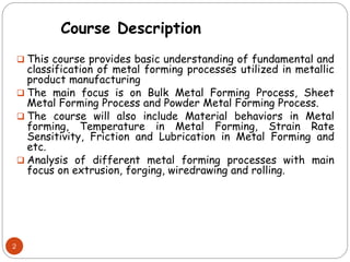
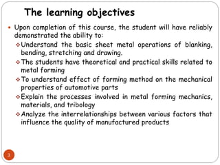
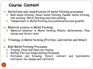
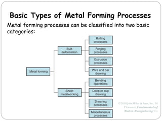
2. This course provides basic understanding of fundamental and
classification of metal forming processes utilized in metallic
product manufacturing
The main focus is on Bulk Metal Forming Process, Sheet
Metal Forming Process and Powder Metal Forming Process.
The course will also include Material behaviors in Metal
forming, Temperature in Metal Forming, Strain Rate
Sensitivity, Friction and Lubrication in Metal Forming and
etc.
Analysis of different metal forming processes with main
focus on extrusion, forging, wiredrawing and rolling.
2
Course Description
3. The learning objectives
Upon completion of this course, the student will have reliably
demonstrated the ability to:
Understand the basic sheet metal operations of blanking,
bending, stretching and drawing.
The students have theoretical and practical skills related to
metal forming
To understand effect of forming method on the mechanical
properties of automotive parts
Explain the processes involved in metal forming mechanics,
materials, and tribology
Analyze the interrelationships between various factors that
influence the quality of manufactured products
3
4. Course Content
Definitions and classification of metal forming processes
Bulk metal forming, Sheet metal forming, Powder metal forming,
Hot working, Warm Working and Cold working,
Temperature in Metal Forming (recrystallization and growth)
Material science in Metal Forming
Material behavior in Metal forming (Plastic deformation, Flow
stress and Strain rate)
Tribology in Metal forming (Friction, Lubrication and Wear)
Bulk Metal Forming Processes
Forging: Close and Open die forging
Rolling: Flat and Shape Rolling Processes
Extrusion and Drawing: Direct, indirect and hydrostatic
extrusion, Die design and Limitation.
4
5. Outline Cont’d
Sheet Metal Forming Processes
Shearing, Stamping, Bending, Blanking, Stretching, Drawings,
Sheet metal formability, Other operations. Sheet Metal
Properties
Powder Metal Forming Processes
Production of Metal Powders
Compaction of Metal Powders
Sintering
Secondary and Finishing Operations
Design Considerations
Process Capabilities
End Use: Mechanical Properties
5
6. Text Book
Fundamentals of powder metallurgy by W. D. Jones
Powder Metallurgy: Principles and Applications by F. V. Lenel
Fundamentals of Powder Metallurgy by I. H. Khan
6
7. Syllabus:
Attendance is your job – come to class!
Or our regularly scheduled time (Thursday, 12:00-1:00 pm & Friday, 8:00 –
10:00 am)
Assignments
Don’t copy from others; don’t plagiarize – its just the right thing to do!!
Tutorials – by Fuseini Abdulai (TA) –
Grading
Class Attendance, Pop Quizzes and Assignments – (10% of your
grade!)
Class Test– (20%)
End of Semester Exams (70%)
7
9. Forming processes
Forming processes are used to convert cast ingots into
basic product forms such as sheets, rods and plates
However, here we will concentrate on forming processes
that produce end products or components.
There are some basic shapes that lend themselves to
manufacture by forming.
Forming processes are particularly good at manufacturing
'linear' objects, that is, long thin ones, where the product
has a constant cross section.
Forming processes involve moving the material through an
opening with the desired shape.
These processes are used for making components such as
fibres, wires, tubes and products such as curtain rails.
9
17. Rolling
The ingot is rolled into the following;
Bloom: square with dimensions (150mm x 150mm)
Slab : rectangular with dimensions (250mm x 40mm)
Billet: square with dimensions (40mm x 40mm)
Flat Rolling: is a type of rolling in which work parts with
rectangular cross sections e.g. slabs and sheets are squeezed
through two rolls to reduce their thickness by an amount called
draft.
𝒅=𝒕𝒐−𝒕𝒇
Where d is draft, 𝒕𝒐 is starting thickness and 𝒕𝒇 is final
thickness
17
18. Flat Rolling
Draft can also be expressed as a fraction of the
starting stock thickness known as reduction.
𝒓=𝒅/𝒕𝒐
As rolling is done to decrease thickness it also
increases the width of the work piece this is known as
spreading.
Spreading occurs in low width to thickness ratio and
low coefficients of friction.
This conserves matter making the volume of metal
entering equal to volume exiting.
18
19. 19
𝑡𝑜 𝑤𝑜𝑙𝑜 = 𝑡𝑓𝑤𝑓𝑙𝑓
𝑤𝑜𝑙𝑜 is starting work width and length
𝑤𝑓𝑙𝑓 is exiting work width and length
Before and after volumes can be related to velocity
entering and exiting
𝑡𝑜 𝑤𝑜𝑣𝑜 = 𝑡𝑓𝑤𝑓𝑣𝑓
The contact point between the roll and the work is σ
Each rolls radius is R
Surface velocity of roll is 𝑽𝒓
Flat Rolling
20. 20
𝑽𝒓 > 𝑽𝒐 is entering velocity of work piece
𝑽𝒓 > 𝑽𝒇 is final velocity of work piece
No slip point or neutral point is the point along the
arc where the work velocity equals the roll velocity.
The amount of slip between the rolls and the work can
be measured by means of forward slip (s).
𝑽𝒇 −𝑽𝒓
s=
𝑽𝒓
True strain based on before and after stock thickness
ϵ = 𝐈𝐧 𝒕𝒐
𝒕𝒇
Flat Rolling
21. 21
Average flow stress; applied to work material in flat
rolling.
where is coefficient of friction
is maximum draft
R is radius
Maximum draft is given as:
Flat Rolling
22. Flat rolling
The above equation is the
force required to maintain
the separation between the
two rolls.
Where L is the length of
contact between the rolls
and the work W is the width
of the work being rolled.
is average flow stress
23. 23
Flat Rolling
Contact length =
Torque = 0.5FL
Power required to drive the rolls
Where F = Rolling force
FL= torque
= angular velocity
= power for each roll
N = rotational speed(revmin)
24. 24
Question
A 300-mm-wide strip 25-mm thick is fed through a rolling mill
with two powered rolls each of radius = 250 mm. The work
thickness is to be reduced to 22 mm in one pass at a roll
speed of 50 rev/min. The work material has a flow curve
defined by K = 275 MPa and n = 0.15, and the coefficient of
friction between the rolls and the work is assumed to be 0.12.
Determine if the friction is sufficient to permit the rolling
operation to be accomplished. If so calculate the:
1. roll force
2. torque
3. horsepower
25. Shape rolling
Shape rolling is a type of rolling where the work is
deformed into a contoured cross section. This is
achieved by passing the work through rolls with the
reverse of the desire shape.
examples of products are Constructional shapes such
as:
I-beam
L-beam
U-channel
Bars and rod
26. Shape rolling
Roll pass design is designing the sequence of intermediate shapes and
their corresponding rolls. Its goal is to achieve uniform deformation
throughout the cross section in each reduction.
Rolling mills: Various rolling mill configurations are available to deal
with the variety of applications and technical problems in the rolling
process.
Two high-rolling mills: it consists of two opposing mills.
The two-high configuration can be either
reversing or non reversing. In the non
reversing mill; the rolls always rotate in
the same direction, and the work always
passes through from the same side.
The reversing mill; allows the direction
of roll rotation to be reversed, so that
the work can be passed through in either
direction.
27. Rolling Mills
Three high-rolling mills Four high-rolling mills
There are three rolls in a vertical
column, and the direction of rotation
of each roll remains unchanged
To achieve a series of reductions, the
work can be passed through from
either side by raising or lowering the
strip after each pass..
The four-high rolling mill uses two
smaller- diameter rolls to contact
the work and two backing rolls
behind them. Owing to the high roll
forces, these smaller rolls would
deflect elastically between their
end bearings as the work passes
through unless the larger backing
rolls were used to support them.
28. Cluster mill Tandem rolling mill
Cluster rolling mill allows
smaller working rolls
against the work.
Tandem rolling mill is
often used to achieve
higher throughput rates in
standard products.
Flat Rolling
29. Several other bulk deformation processes use rolls to form the
work part. The operations include thread rolling, ring rolling, gear
rolling, and roll piercing.
Thread rolling is used to form threads on cylindrical parts by
rolling them between two dies.
It is the most important commercial process for mass producing
external threaded components (e.g., bolts and screws).
Most thread rolling operations are performed by cold working in
thread Rolling machines.
Advantages of thread rolling over machining
better material utilization.
stronger threads due to work hardening.
smoother surface.
better fatigue resistance due to compressive stresses introduced
by rolling.
29
Other deformation processes related to rolling
31. Ring rolling
Ring rolling is a deformation process in which a thick-walled ring of
smaller diameter is rolled into a thin-walled ring of larger diameter.
Ring rolling used to reduce the wall thickness and increase the
diameter of a ring.
As the thick-walled ring is compressed, the deformed material
elongates, causing the diameter of the ring to be enlarged.
Ring rolling is usually performed as a hot-working process for large
rings and as a cold-working process for smaller rings.
Advantages of ring rolling over alternative methods of making the same
parts:
raw material savings.
ideal grain orientation for the application.
strengthening through cold working.
33. Gear rolling is a cold working process to produce certain
gears. The automotive industry is an important user of
these products.
The setup in gear rolling is similar to thread rolling,
except that the deformed features of the cylindrical
blank or disk are oriented parallel to its axis (or at an
angle in the case of helical gears) rather than spiraled
as in thread rolling.
Advantages of gear rolling
higher production rates.
better strength and fatigue resistance.
less material waste.
33
Gear rolling
34. Roll piercing
Ring piercing is a specialized hot working process for
making seamless thick-walled tubes.
The process is based on the principle that when a solid
cylindrical part is compressed on its circumference high
tensile stresses are developed at its center.
Compressive stresses on a solid cylindrical billet are
applied by two rolls, whose axes are oriented at slight
angles from the axis of the billet, so that their rotation
tends to pull the billet through the rolls.
A mandrel is used to control the size and finish of the hole
created by the action.
35. Roll piercing
Roll piercing:
(a) formation of internal stresses and cavity by compression of
cylindrical part;
(b) setup of Mannesmann roll mill for producing seamless tubing.
36. Forging
Forging is a deformation process in which the work is
compressed between two dies, using either impact or gradual
pressure to form the part.
One way to classify the operations is by
Working temperature; most forging operations are performed
hot or warm, owing to the significant deformation demanded by
the process and the need to reduce strength and increase
ductility of the work metal.
Equipment used; A forging machine that applies an impact load is
called a forging hammer, while one that applies gradual
pressure is called a forging press.
These components include engine crankshafts and
connecting rods, gears, aircraft structural
components, and jet engine turbine parts.
37. Forging
Degree to which the flow of the work metal is constrained by
the dies.
By this classification, there are three types of forging
operations
open-die forging
impression-die forging
flashless forging.
Open-die forging ;the work is
compressed between two flat
dies, thus allowing the metal
to flow without constraint in a
lateral direction relative to
the die surfaces.
38. Forging
Impression-die forging, the die surfaces contain a shape or
impression that is imparted to the work during compression, thus
constraining metal flow to a significant degree.
Flash is a portion of the
work metal that flows
beyond the die impression
excess metal that must be
trimmed off later
Flashless forging, the work is
completely constrained within the
die and no excess flash is
produced. The volume of the
starting work piece must be
controlled very closely so that it
matches the volume of the die
cavity
39. Upsetting Or Upset Forging
Upsetting or upset forging is a type of forging in which a cylindrical
metal is compressed in two flat dies, reducing its height and increasing
its width.
Analysis of open die forging
If its carried under conditions of no friction between work and die
surface there is homogenous deformation and radial flow is uniform
throughout the height.
Under these ideal conditions, the true strain experienced by the work
during the process can be determined by;
o where 𝒉𝒐 is starting height of the work, mm (in)
o and h is the height at some intermediate point in the process, mm (in).
At the end of the compression stroke, h is its final value 𝒉𝒇, and the
true strain ∈ reaches its maximum value.
41. Upset Forging
force required to continue the compression at any given
height h during the process can be obtained by
multiplying the corresponding cross-sectional area by the
flow stress: F= 𝒀𝒇A
F=force, lb (N);
A=cross-sectional area of the part, mm2 (in2);
Yf=flow stress
Area A continuously increases during the operation as
height is reduced. Flow stress Yf also increases as a
result of work hardening, except when the metal is
perfectly plastic (e.g., in hot working). In this case, the
strain- hardening exponent n = 0, and flow stress Yf
equals the metal’s yield strength Y.
42. Upset Forging
An actual upsetting operation does not occur quite shown in the
above slide because friction opposes the flow of work metal at
the die surfaces. This creates the barreling effect.
When performed on a hot work part with cold dies, the
barreling effect is even more pronounced.
This results from a higher coefficient of friction typical in hot
working and heat transfer at and near the die surfaces, which
cools the metal and increases its resistance to deformation.
The hotter metal in the middle of the part flows more readily
than the cooler metal at the ends.
These effects are more significant as the diameter to-height
ratio of the work part increases, due to the greater contact
area at the work–die interface.
43. Upset forging
Actual deformation of a cylindrical workpart in open-die
forging, showing pronounced barreling: (1) start of process, (2)
partial deformation, and (3) final shape.
44. Upset forging
All of these factors cause the actual upsetting force to be greater
than what is predicted by the previous equation.
As an approximation, we can apply a shape factor to the previous eqn
to account for effects of the D/h ratio and friction:
F =𝑲𝒇𝒀𝒇𝑨
𝑲𝒇 is the forging shape factor
where 𝜇 is coefficient of friction;
D is work part diameter or other dimension representing
contact length with die surface, mm (in);
h is work part height, mm (in).
45. Upset forging
QUESTION
A cylindrical work piece is subjected to a cold upset forging
operation. The starting piece is 75 mm in height and 50mm
in diameter. It is reduced in the operation to a height of
36mm. The work material has a flow curve defined by
K=350MPa and n= 0.17.Assume a coefficient of friction of
0.1.
1. Determine the force as the process begins,
2. at intermediate heights of 62mm, 49 mm, and at the
final height of 36 mm.
46. Related Operation To Upset Forging
Fullering is a forging operation performed to reduce the
cross section and redistribute the metal in a work part
in preparation for subsequent shape forging. It is
accomplished by dies with convex surfaces.
Edging is similar to fullering, except that the dies have
concave surfaces.
Cogging operation consists of a sequence of forging
compressions along the length of a work piece to reduce
cross section and increase length.
47. 47
Extrusion is a compression process in which the work
piece is forced to flow through a die opening to produce
a desired cross sectional shape.
Extrusion
48. Extrusion
ADVANTAGES
(1) a variety of shapes are possible, especially with hot
extrusion;
(2) grain structure and strength properties are
enhanced in cold and warm extrusion
(3) fairly close tolerances are possible, especially in cold
extrusion;
(4) in some extrusion operations, little or no wasted
material is created.
•NB: A limitation is that the cross section of the
extruded part must be uniform throughout its length.
49. Extrusion
Extrusion is carried out in various ways i.e either
direct extrusion and indirect extrusion.
working temperature: cold, warm, or hot extrusion.
DIRECT EXTRUSION (forward extrusion)
A metal billet is loaded into a container, and a ram
compresses the material, forcing it to flow through
the die opening at the opposite end of the container.
BUTT: it’s a small portion of the metal that remains in
the container after the compression. It cuts off just
beyond the exit of the die.
50. Extrusion
Direct extrusion
One of the problems in
direct extrusion is the
significant friction
that exists between
the work surface and
the walls of the
container as the billet
is forced to slide
toward the die
opening.
This friction causes a
substantial increase in
the ram force required
in direct extrusion.
51. Extrusion
Hollow sections (e.g., tubes) are possible in direct extrusion. The
starting billet is prepared with a hole parallel to its axis. This allows
passage of a mandrel that is attached to the dummy block.
As the billet is compressed, the material is forced to flow through
the clearance between the mandrel and the die opening. The
resulting cross section is tubular.
End product of
hollow extrusion
52. Extrusion
INDIRECT EXTRUSION (BACKWARD EXTRUSION AND REVERSE
EXTRUSION)
In indirect extrusion, the die is mounted to the ram rather than
at the opposite end of the container. As the ram penetrates into
the work, the metal is forced to flow through the clearance in
direction opposite to the motion of the ram.
Since the billet is not
forced to move relative to
the ram, there is no friction
thereby requires less force
in indirect extrusion.
53. Extrusion can be performed either hot or cold, depending
on work metal and amount of strain to which it is
subjected during deformation.
Hot extrusion involves prior heating of the billet to a
temperature above its recrystallization temperature. This
reduces strength and increases ductility of the metal,
permitting more extreme size reductions and more
complex shapes to be achieved in the process.
Additional advantages
reduction of ram force,
increased ram speed,
reduction of grain flow characteristics in the final product.
Hot versus Cold extrusion
54. Hot versus Cold Extrusion
Lubrication is critical in hot extrusion for certain metals (e.g.,
steels),
Glass is sometimes used as a lubricant in hot extrusion; in
addition to reducing friction, it also provides effective thermal
insulation between the billet and the extrusion container.
Cold extrusion and warm extrusion are generally used to produce
discrete parts, often in finished (or near finished) form. The
term impact extrusion is used to indicate high-speed cold
extrusion.
ADVANTAGES
increased strength due to strain hardening,
Close tolerances
improved surface finish,
absence of oxide layers, and high production rates.
Cold extrusion at room temperature also eliminates the need
for heating the starting billet.
57. Analysis of extrusion
In fact, extrusion is not a frictionless process, and the
previous equations grossly underestimate the strain and
pressure in an extrusion operation.
Friction exists between the die and the work as the billet
squeezes down and passes through the die opening.
In direct extrusion, friction
also exists between the
container wall and the billet
surface.
The effect of friction is to
increase the strain
experienced by the metal.
Thus, the actual pressure is
greater than that given by
Eq. (19.21), which assumes no
friction.
61. Analysis of Extrusion
where the term 2L/Do accounts for the additional pressure
due to friction at the container– billet interface.
L is the portion of the billet length remaining to be
extruded,
and Do is the original diameter of the billet.
Note that p is reduced as the remaining billet length
decreases during the process.
Ram force in indirect or direct extrusion is simply pressure
p from Eqs. (19.23a) or respectively, multiplied by billet
area Ao:
F = pAo
64. Extrusion
QUESTION
•A billet 75mm long and 25mm in diameter is to be extruded
in a direct extrusion operation with extrusion ratio rx = 4.0.
The extrudate has a round cross section. The die angle
(halfangle) =90. The work metal has a strength coefficient =
415 MPa, and strain-hardening exponent = 0.18. Use the
Johnson formula with a = 0.8 and b =1.5 to estimate extrusion
strain. Determine the pressure applied to the end of the
billet as the ram moves forward.
TIP
•Let us examine the ram pressure at billet lengths of L=75mm
(starting value), L=50 mm, L=25 mm, and L=0.
•We compute the ideal true strain, extrusion strain using
Johnson’s formula, and average flow stress.
65. Wire and Bar Drawing
Drawing is an operation in which the cross section of a bar, rod, or
wire is reduced by pulling it through a die opening.
The basic difference between bar drawing and wire drawing is the
stock size that is processed.
Bar drawing is the term used for large diameter bar and rod stock,
while wire drawing applies to small diameter stock.
Since compression is used to squeeze the metal to be pilled from the
die it is termed indirect compression.
Bar drawing is generally accomplished as a single-draft operation—
the stock is pulled through one die opening to give the smaller final
diameter since the beginning stock has a large diameter.
66. Wire drawing is accomplished using a series of draw dies
since its drawn from coils of wires the number of dies
varies typically between 4 and 12.
Drawing of bar, rod or wire.
Wire and Bar Drawing
67. Analysis of drawing
In a drawing operation, the change in size of the work is usually
given by the area Reduction, defined as follows
where r=area reduction in drawing; Ao=original area of
work,mm2 ; and Af=final area, mm2. Area reduction is often
expressed as a percentage. is draft.
If no friction or redundant work occurred in drawing, true
strain could be determined as follows:
r is drawing reduction.
The stress that results from this ideal deformation is given by
68. Analysis of drawing
When friction is considered
where 𝝈𝒅 = draw stress, MPa; 𝝁 = die-work coefficient of
friction; 𝜶 = die angle (half-angle) and ∅ is a factor that
accounts for inhomogeneous deformation which is
determined as follows for a round cross section:
where D =average diameter of work during drawing, and
Lc =contact length of the work with the draw die.
69. Analysis
The corresponding draw force is then the area of the
drawn cross section multiplied by the draw stress:
Where F is draw force.
Question
Wire is drawn through a draw die with entrance angle=15.
Starting diameter is 2.5mm and final diameter is 2.0 mm.
The coefficient of friction at the work–die interface is
0.07. The metal has a strength coefficient K is 205 MPa
and a strain- hardening exponent n is 0.20. Determine the
draw stress and draw force in this operation.
70. Wire and Bar Drawing
ADVANTAGES
(1) close dimensional control,
(2) good surface finish,
(3) improved mechanical properties such as strength and
hardness,
(4) adaptability to economical batch or mass production.
71. 71
Drawing is a forming
process in which the
diameter of a round wire or
bar is reduced by pulling it
through a die opening
Extrusion is a forming
process in which the metal
is forced to flow through a
die opening to take the
shape of the opening as its
cross sectional shape.
Difference Between Extrusion and Drawing
Extrusion and wire and bar drawing
74. Sheet and Plate Metal Products
Sheet and plate metal parts for consumer and
industrial products such as
Automobiles and trucks
Airplanes
Railway cars and locomotives
Farm and construction equipment
Small and large appliances
Office furniture
Computers and office equipment
74
75. Advantages of Sheet Metal Parts
High strength
Good dimensional accuracy
Good surface finish
Relatively low cost
For large quantities, economical mass production
operations are available
75
76. Sheet Metalworking Terminology
1. ―Punch-and-die‖
Tooling to perform cutting, bending, and
drawing
2. ―Stamping press‖
Machine tool that performs most sheet metal
operations
3. ―Stampings‖
Sheet metal products
76
78. I. Cutting
Shearing between two sharp cutting edges
78
Cutting and forming operations performed on relatively thin sheets of metal
79. Shearing, Blanking, and Punching
Three principal operations in pressworking that cut
sheet metal:
Shearing
Blanking
Punching
79
Shearing: Sheet metal cutting
operation along a straight
line between two cutting
edges
Typically used to cut large
sheets into smaller sections
for subsequent operations
80. Blanking and Punching
Blanking - sheet metal cutting to separate piece from
surrounding stock
Cut piece is the desired part, called a blank
Punching - sheet metal cutting similar to blanking except
cut piece is scrap, called a slug
Remaining stock is the desired part
(a) Blanking and (b) punching
80
81. Clearance in Sheet Metal Cutting
Distance between the punch and die
Typical values range between 4% and 8% of stock thickness
If too small, fracture lines pass each other, causing double
burnishing and larger force
If too large, metal is pinched between cutting edges and
excessive burr results
81
83. The clearance between punch and dies is represented by
the total difference, which is one of the critical factors
in the punching process
For example, when using diameter 12 upper die and
diameter 12.25 lower die, the optimal clearance is
0.25mm
Improper clearance will reduce the die service life, or
burrs and lead to secondary cutting the irregular opening
will increase the demounting force, etc.
Besides, the die clearance is subject to the material and
thickness, generally, for carbon steel plate, 12% - 18% of
the thickness is best
83
Punch and Die Clearance
84. How to Determine Punch and Die Clearance
84
If no special requirements in CNC punch, you can refer to the
following table for selecting the die clearance:
85. Punching
If you punch round holes or square holes, or some other forms of
holes through a given thickness of metal, you just want to know the
force required to punch a hole in steel
You can calculate the punching tonnage been required with the help of
the following punching force calculation formula (blanking force
formula):
85
e.g: If punching one square hole in the 3 mm thickness low carbon steel
plate, side length 20 mm, you will get:
Perimeter=20x4=80 mm
Thickness=3 mm
Shear Strength=0.3447 kN/mm2
Punch Force (kN)=80X3X0.3447=82.728kN
convert into tonnage: 82.728kN /9.81= 8.43 ton
86. II. Bending
Straining sheetmetal around a straight axis to take
a permanent bend
(a) Bending of sheet metal (b) both compression and tensile
elongation of the metal occur in
bending
86
87. Types of Sheetmetal Bending
V-bending - performed with a V-shaped die
87
For low production
Performed on a press brake
V-dies are simple and inexpensive
Edge bending - performed with a wiping die
For high production
Pressure pad required
Dies are more complicated
and costly
88. Springback in Bending
Springback = increase in included angle of bent part
relative to included angle of forming tool after tool is
removed
Reason for springback:
When bending pressure is removed, elastic energy
remains in bent part, causing it to recover partially
toward its original shape
88
89. III. Drawing
Sheet metal forming to make cup-shaped, box-shaped, or
other complex-curved, hollow-shaped parts
Products: beverage cans,
ammunition shells,
automobile body panels
89
90. IV. Shapes other than Cylindrical Cups
Square or rectangular boxes (as in sinks),
Stepped cups,
Cones,
Cups with spherical rather than flat bases,
Irregular curved forms (as in automobile body panels)
Each of these shapes presents its own unique technical
problems in drawing
90
91. Makes wall thickness of cylindrical cup more uniform
Examples: beverage cans and artillery shells
Ironing to achieve a more uniform wall thickness in a drawn cup:
(1) start of process; (2) during process
Note thinning and elongation of walls
91
Ironing
92. Used to create indentations in sheet, such as raised
(or indented) lettering or strengthening ribs
Embossing: (a) cross-section of punch and die configuration
during pressing; (b) finished part with embossed ribs
92
Embossing
93. Guerin Process
Rubber pad can be used with
different form blocks
Process attractive in small
quantity production
93
Guerin process is a sheet metal forming process that uses
a rubber die that flexes to force the sheet metal to take
the shape of a form block (punch)
Advantages of Guerin Process
Low tooling cost
Form block can be made of wood, plastic, or other
materials that are easy to shape
94. Dies for Sheet Metal Processes
Most pressworking operations performed with
conventional punch-and-die tooling
The term stamping die sometimes used for high
production dies
94
95. Dies for Sheet Metal Processes
(a) Progressive die;
(b) associated strip
development
95
96. Several sheet metal parts produced on a turret press, showing
variety of hole shapes possible
(photo courtesy of Strippet, Inc.)
96
97. Sheet Metal Operations
Not Performed on Presses
1. Stretch forming
2. Roll bending and forming
3. Spinning
4. High-energy-rate forming processes.
97
98. Sheet metal is stretched and simultaneously bent to
achieve shape change
Stretch forming: (1) start of process; (2) form die is pressed
into the work with force Fdie, causing it to be stretched and
bent over the form. F = stretching force
98
1. Stretch Forming
99. Large metal sheets and plates are formed
into curved sections using rolls
Roll bending
99
2. Roll Bending
100. Continuous bending process in which opposing rolls
produce long sections of formed shapes from coil or
strip stock
Roll forming of a continuous channel section:
(1) straight rolls (2) partial form
(3) final form
100
2. Roll Forming
101. 3. Spinning
Metal forming process in which an axially symmetric
part is gradually shaped over a rotating mandrel using a
rounded tool or roller
Conventional spinning: (1) setup at start of process; (2) during
spinning; and (3) completion of process
101
102. 4. High-Energy-Rate Forming (HERF)
Processes to form metals using large amounts of
energy over a very short time
HERF processes include:
Explosive forming
Electrohydraulic forming
Electromagnetic forming
102
103. Explosive Forming
Use of explosive charge to form sheet (or plate) metal into a
die cavity
Explosive charge causes a shock wave whose energy is
transmitted to force part into cavity
Applications: large parts, typical of aerospace industry
Explosive forming:
(1) setup, (2) explosive is detonated, and
(3) shock wave forms part and plume escapes water surface
103
104. Electromagnetic Forming
Sheet metal is deformed by mechanical force of an
electromagnetic field induced in workpart by an
energized coil
Presently, it is the most widely used HERF process
Applications: tubular parts
Electromagnetic forming: (1) setup in which coil is inserted into
tubular workpart surrounded by die; (2) formed part
104
113. Isothermal forming
Isothermal forming refers to forming operations that
are carried out in such a way as to eliminate surface
cooling and the resulting thermal gradients in the work
part.
It is accomplished by preheating the tools that come in
contact with the part to the same temperature as the
work metal.
This weakens the tools and reduces tool life.
NB: read more on isothermal forming!!!
Read on strain rate sensitivity!!!
113
123. Friction and lubrication in forming
Friction encountered in metal forming is different from that
in most mechanical systems. E.g. Shafts and bearings.
These involve relative motion between surfaces characterized
by low contact, pressure and low to moderate temperatures.
By contrast, the metal forming environment features high
pressures between a hardened tool and a soft work part,
plastic deformation of the softer material, and high moderate
temperatures. (at least in hot working).
These conditions can result in relatively high coefficients of
friction in metalworking, even in the presence of lubricants.
If the coefficient of friction becomes large enough, a
condition known as sticking occurs.
123
127. Powder Metallurgy: Introduction
Earliest use of iron powder dates back to 3000 BC.
Egyptians used it for making tools
Modern era of P/M began when tungsten (W) lamp
filaments were developed by Edison
Components can be made from pure metals, alloys, or
mixture of metallic and non-metallic powders
Commonly used materials are iron, copper, aluminium,
nickel, titanium, brass, bronze, steels and refractory
metals
Used widely for manufacturing gears, cams, bushings,
cutting tools, piston rings, connecting rods, impellers
etc.
128. Powder Metallurgy
. . . is a forming technique
Essentially, Powder Metallurgy (PM) is
an art & science of producing metal or
metallic powders, and using them to
make finished or semi-finished
products.
Particulate technology is probably the
oldest forming technique known to man
There are archeological evidences to
prove that the ancient man knew
something about it
129. History of Powder Metallurgy
IRON Metallurgy >
How did Man make iron in 3000 BC?
Did he have furnaces to melt iron air blasts, and
The reduced material, which would then be spongy, used to be
hammered to a solid or to a near solid mass.
Example: The IRON PILLER at Delhi
An important point that comes out :
The entire material need not be melted to fuse it.
The working temperature is well below the Tm of the major
constituent, making it a very suitable method to work with
refractory materials, such as: W, Mo, Ta, Nb, oxides, carbides, etc.
It began with Platinum technology about 4 centuries ago … in those
days, Platinum, [mp = 1774°C], was "refractory", and could not be
melted.
130. Powder Metal Materials
Elemental
A pure metal, most commonly iron, aluminum or
copper
Prealloyed
An alloy of the required composition, most commonly
copper alloys, stainless steel or high-speed steel
131. Powder Metallurgy Process
Powder metallurgy involves Powder production, Blending
or mixing, Powder compaction, Sintering and Finishing
Operations
133. Atomization
Produces a liquid-metal stream by
injecting molten metal through a
small orifice
The stream is broken up by jets
of inert gas or air
The size of the particle formed
depends on the temperature of
the metal, metal flowrate through
the orifice, nozzle size and jet
characteristics
Water or gas atomization; Fe powders made by atomization
134. The size and shape of
the particles from
atomization depend on
the temperature, flow
rate, size of nozzle, and
the jet characteristics
When water is used it
creates a slurry metal
powder and leaves a liquid
at the bottom of the
atomization chamber
The water cools the
metal faster for a higher
production rates
Atomization
135. Centrifugal Atomization
The process in which the molten-metal drops onto a
rapidly rotating disk or cup
The centrifugal forces break up the molten-metal
stream to generate particles
Another method is that a consumable electrode is
rotating rapidly in a helium filled chamber
(a) Centrifugal atomization; (b) Rotating electrode
(a) (b)
136. Electrode Centrifugation
Variation:
A consumable electrode is
rotated rapidly in a helium-
filled chamber. The
centrifugal force breaks up
the molten tip of the
electrode into metal particles.
Ni-based superalloy made by the rotating electrode process
137. Reduction of Metal Oxides
A process that uses
gases as a reducing
agent
Hydrogen and carbon
monoxide
Also known as the
removal of oxygen
Very fine metallic
oxides are reduced to
the metallic state
Spongy and porous
powders are produced
138. Electrolytic Deposition and Carbonyls
Electrolytic Deposition
utilizes either aqueous
solutions or fused salts
Makes the purest powders
that are available
Metal carbonyls are formed by
letting iron or nickel react with
carbon monoxide
Reaction product is decomposed
to iron and nickel
Forms small, dense, uniform
spherical particles
139. Mechanical Comminution
Also known as pulverization
Involves roll crushing,
milling in a ball mill, or
grinding of brittle or less
ductile metals into small
particles
Brittle materials have
angular shapes
Ductile metals are flaky
and not particularly suitable
for P/M
140. Mechanical Alloying
Powders of two or more pure metals are mixed in a ball mill
Under the impact of the hard balls the powders fracture and bond
together by diffusion, forming alloy powders
The dispersed phase can result in strengthening of the particles or
can impart special electrical or magnetic properties
142. Types of Powders
Nanopowders
Consist of mostly copper,
aluminum, iron, titanium
Are pyrophoric (ignite
spontaneously)
Contaminated when exposed
to air
The particle size is reduced
and becomes porous free
when subjected to large
plastic deformation by
compression and shear
stress
Posses enhanced properties
Microencapsulated powders
Coated completely with a
binder
The binder acts as an
insulator for electrical
applications preventing
electricity from flowing
between particles
Compacted by warm pressing
The binder is still in place
when used
144. Particle Size, Shape, and Distribution
Particle size is measured by a process called screening
Screening is the passing of metal powder through
screens of various mesh sizes
The main process of screening is Screen Analysis
Screen analysis uses a vertical stack of screens with
mesh size becoming finer as the powder flows down
through screens
The process of
separating particles
by size is called
classification
145. Other Screening Methods
Sedimentation
Involves measuring the
rate at which particles
settle in a fluid
Microscopic Analysis
Includes the use of
transmission and
scanning electron
microscopy
Optical
Particles block a beam
of light and then
sensed by a photocell
Light Scattering
A laser that illuminates a
sample consisting of
particles suspended in a
liquid medium
The particles cause the
light to be scattered,
and a detector then
digitizes and computes
the particle-size
distribution
Suspending Particles
Particles suspended in a
liquid and then detected
by electrical sensors
146. Particle Shape and Shape Factor
Major influence on
processing
characteristics
Usually described by
aspect ratio and shape
factor
Aspect ratio is the
ratio of the largest
dimension to the
smallest dimension
Ratio ranges from unity
(spherical) to 10
(flake-like, needle-like
Shape factor (SF) is also
called the shape index
Is a measure of the ratio
of the surface area to its
volume
The volume is normalized
by a spherical particle of
equivalent volume
The shape factor for a
flake is higher than it is
for a sphere
147. Particle Size
void
smaller, more numerous voids
voids filled by smaller particles,
small voids remain
Mixing particles of different sizes allows decreased
porosity and a higher packing ratio
148. Size Distribution and Other Properties
Size distribution is important because it affects the
processing characteristics of the powder
Flow properties, compressibility and density are
other properties that have an affect on metal
powders behavior in processing them
Flow
When metal powders are being filled into dies
Compressibility
When metal powders are being compressed
Density
Theoretical density, apparent density, and the
density when the powder is shaken or tapped in the
die cavity
150. 2. Blending or Mixing
Blending a coarser fraction with a
finer fraction ensures that the
interstices between large particles
will be filled out.
Powders of different metals and
other materials may be mixed in
order to impart special physical and
mechanical properties through
metallic alloying.
Lubricants may be mixed to improve the powders’ flow
characteristics.
Binders such as wax or thermoplastic polymers are added
to improve green strength.
Sintering aids are added to accelerate densification on
heating.
Range of particle sizes
151. Blending
To make a homogeneous mass with uniform
distribution of particle size and composition
Powders made by different processes have different sizes and
shapes
Mixing powders of different metals/materials
Add lubricants (<5%), such as graphite and stearic acid, to
improve the flow characteristics and compressibility of
mixtures
Combining is generally carried out in
Air or inert gases to avoid oxidation
Liquids for better mixing, elimination of dusts and reduced
explosion hazards
Hazards
Metal powders, because of high surface area to volume ratio
are explosive, particularly Al, Mg, Ti, Zr, Th
152. Some common equipment geometries used for blending powders
(a) Cylindrical, (b) rotating cube, (c) double cone, (d) twin shell
Blending
153. Reasons for Blending
To impart special physical and mechanical properties and
characteristics
Proper mixing is essential to ensure the uniformity of
mechanical properties throughout the part
Even one metal can have powder vary in size and shape
The ideal mix is one in which all of the particles of each
material are distributed uniformly
Lubricants can be mixed with the powders to improve
flow of metal powder into dies, reduce friction between
metal particles, and improve the die life
Binders are used to develop sufficient green strength
Other additives can be used to facilitate sintering
154. Hazards
Metal powders are explosive because of the high
surface area-to-volume ratio (mostly aluminum,
magnesium, titanium, zirconium, and thorium
Most be blended, stored, handled with great care
Precautions
Grounding equipment
Preventing sparks
Avoiding friction as a source of heat
Avoiding dust clouds
Avoiding open flames
Avoiding chemical reactions
155. W. Li
155
3. Powder Consolidation
Die pressing
Cold compaction with 100 – 900
MPa to produce a ―Green body‖.
Die pressing
Cold isostatic pressing
Rolling
Gravity
Injection Molding small, complex
parts.
156. Compaction
Press powder into the desired shape and size in dies
using a hydraulic or mechanical press
Pressed powder is known as ―green compact‖
Stages of metal powder compaction:
157.
158. Increased compaction pressure
Provides better packing of particles and leads to ↓
porosity
↑ localized deformation allowing new contacts to be
formed between particles
Compaction
159. At higher pressures, the green density approaches density of
the bulk metal
Pressed density greater than 90% of the bulk density is
difficult to obtain
Compaction pressure used depends on desired density
Compaction
1
3
2
160. W. Li
Friction problem in cold compaction
The effectiveness of pressing with a single-acting
punch is limited. Wall friction opposes compaction.
The pressure tapers off rapidly and density diminishes
away from the punch.
Floating container and two counteracting punches help
alleviate the problem.
161. Smaller particles provide greater strength mainly due to
reduction in porosity
Size distribution of particles is very important. For same size
particles minimum porosity of 24% will always be there
Box filled with tennis balls will always have open space between
balls
Introduction of finer particles will fill voids and result in ↑ density
Effect of Particles Size on Strength and Porosity
162. Because of friction between (i) the metal particles and (ii) between
the punches and the die, the density within the compact may vary
considerably
Density variation can be minimized by proper punch and die design
(a)and (c) Single action press; (b) and (d) Double action press
(e) Pressure contours in compacted copper powder in single action press
Effect of Friction
163. Presses
Press capacities are on the
order of 200 to 300 tons
Most projects require less
than 100 tons
Small tonnage, crank- or
eccentric-type mechanical
presses are used
For higher capacities, toggle
or knuckle-joint presses are
employed
Hydraulic presses can
have capacities up to
5,000 tons and are
used for large parts
The type of press
selected depends on
part size and its
configuration, density
requirements, and
production rate
165. Metal powder placed in a
flexible rubber mold
Mold made of elastomer
(neoprene rubber, urethane,
polyvinyl chloride)
Assembly pressurized
hydrostatically by water
(400 – 1000 MPa)
Typical: Automotive cylinder
liners
Cold Isostatic Pressing
166. Hot Isostatic Pressing (HIP)
High-melting-point sheet
metal
High temp inert gas or
vitreous fluid
Pressures as high as 100
MPa
Temperatures of 1200˚C
(2200˚F)
Used for making high-
quality parts
Ex. valve lifter
Advantages:
100% density
Good metallurgical bonding of
the particles
Good mechanical properties
Compacts of uniform grain
structure and density
Disadvantages:
Wider dimensional tolerances
Higher equipment cost and
production time
Small production quantities
167. 4. Sintering
Parts are heated to 0.7~0.9 Tm.
Transforms compacted mechanical
bonds to much stronger metallic bonds.
Shrinkage always occurs:
sintered
green
green
sintered
V
V
shrinkage
Vol
_
3
/
1
_
sintered
green
shrinkage
Linear
168. Sintering – Compact Stage
Green compact obtained after compaction is brittle and
low in strength
Green compacts are heated in a controlled-atmosphere
furnace to allow packed metal powders to bond together
Sintering – Three Stages
Carried out in three stages:
First stage: Temperature is slowly increased so that all
volatile materials in the green compact that would
interfere with good bonding is removed
Rapid heating in this stage may entrap gases and
produce high internal pressure which may fracture
the compact
169. Promotes vapor-phase transport
Because material heated very
close to MP, metal atoms will be
released in the vapor phase from
the particles
Vapor phase resolidifies at the
interface
Sintering: High temperature stage
170. Third stage: Sintered product is cooled in a
controlled atmosphere
Prevents oxidation and thermal shock
Gases commonly used for sintering:
H2, N2, inert gases or vacuum
Sintering: High temperature stage
171. Liquid Phase Sintering
During sintering a liquid phase, from the lower MP
component, may exist
Alloying may take place at the particle-particle
interface
Molten component may surround the particle that
has not melted
High compact density can be quickly attained
Important variables:
Nature of alloy, molten component/particle wetting,
capillary action of the liquid
172. Combined Stages
Simultaneous compaction + sintering
Container: High MP sheet metal
Container subjected to elevated temperature and a very high
vacuum to remove air and moisture from the powder
Pressurizing medium: Inert gas
Operating conditions
100 MPa at 1100 C
Produces compacts with almost 100% density
Good metallurgical bonding between particles and good mechanical
strength
Uses
Superalloy components for aerospace industries
Final densification step for WC cutting tools and P/M tool steels
173. (i) Slip is first poured into an absorbent mould
(ii) a layer of clay forms as the mould surface absorbs water
(iii) when the shell is of suitable thickness excess slip is poured away
(iv) the resultant casting
Slip-Casting
174. Slip: Suspension of colloidal (small particles that do
not settle) in an immiscible liquid (generally water)
Slip is poured in a porous mold made of plaster of
paris. Air entrapment can be a major problem
After mold has absorbed some water, it is inverted
and the remaining suspension poured out.
The top of the part is then trimmed, the mold opened,
and the part removed
Application: Large and complex parts such as plumbing
ware, art objects and dinnerware
Slip-Casting
175. 5. Finishing
The porosity of a fully sintered part is still significant
(4-15%).
Density is often kept intentionally low to preserve
interconnected porosity for bearings, filters, acoustic
barriers, and battery electrodes.
However, to improve properties, finishing processes are
needed:
Cold restriking, resintering, and heat treatment.
Impregnation of heated oil.
Infiltration with metal (e.g., Cu for ferrous parts).
Machining to tighter tolerance.
176. Special Process: Hot compaction
Advantages can be gained by combining consolidation
and sintering,
High pressure is applied at the sintering temperature
to bring the particles together and thus accelerate
sintering.
Methods include:
Hot pressing
Spark sintering
Hot isostatic pressing (HIP)
Hot rolling and extrusion
Hot forging of powder preform
Spray deposition
177. (i)Avoid sharp corners and thus the corners have to be either
radiused or chamfered.
(ii) As under-cuts and re-entrant angles cannot be molded into the
component (conventional pressing & sintering), these have to be
machined subsequently.
(iii) The inability of the powder metallurgy process to introduce
cross holes. Such features would have to be machined using a post
processing step.
(iv) To prevent excessive wear of the tools chamfers greater than
45o are preferred, but in case of less than 45o degrees lands are
required.
(v) Punches less than 1 mm be avoided.
(vi) Large sectional changes should be avoided as far as possible as
they may lead to the cracking of the green component at the
change in section through transfer of metal powder into the wide
section during the compaction processes.
Design Considerations for P/M Components:
178. Design Aspects
(a) Length to thickness ratio limited to 2-4; (b) Steps limited to avoid density
variation; (c) Radii provided to extend die life, sleeves greater than 1 mm, through
hole greater than 5 mm; (d) Feather-edged punches with flat face; (e) Internal
cavity requires a draft; (f) Sharp corner should be avoided; (g) Large wall thickness
difference should be avoided; (h) Wall thickness should be larger than 1 mm.
180. (vii) The practical minimum diameter which can be easily molded
is about 2 mm and holes running parallel to the direction of
pressing should normally have a length to diameter ratio of
4 : 1.
(viii) Groves are generally molded into the top face of the
component and these should not extend to more than 30 %
of the total length.
(ix) Tolerances on sintered components can be improved by sizing
at extra cost as per design requirements.
Tolerances after sintering are generally equivalent to those
obtained by turning, milling, etc.
But after sizing these may be considered equivalent to
medium grinding or broaching.
Design Considerations for P/M Components:
181. P/M Applications
Electrical Contact materials
Heavy-duty Friction materials
Self-Lubricating Porous bearings
P/M filters
Carbide, Alumina, Diamond cutting tools
Structural parts
P/M magnets
Cermets
and more, such as high tech applications
182. Motor Cycle Parts Vehicles Engine Parts
Industrial Machines Parts Industrial Machines Parts
P/M Applications
184. Powdered Metal Transmission Gear Powdered Metal Turbine blade-disk
P/M Applications
Oil-impregnated Porous Bronze Bearings Metal filters
185. These may be classified into two main headings;
(a) Cost advantages, and
(b) Advantages due to particular properties of sintered components.
Cost Advantages:
(i) Zero or minimal scrap;
(ii) Avoiding high machining cost in mass production as irregularly
shaped holes, flats, counter bores, involute gear teeth, key-ways
can be molded into the components;
(iii) Extremely good surface finish at very low additional cost after
sizing and coining;
(iv) very close tolerance without a machining operation;
(v) Assembly of two or more parts (by I/M) can be made in one
piece;
(vi) Separate parts can be combined before sintering.
(vii) High production rates
Advantages of P/M for Structural Components:
186. (i) By achieving up to 95% density, the mechanical and
physical properties are comparable with cast materials
and in certain cases with wrought materials. In certain
cases 99.9 % dense structure can be obtained (liquid
phase sintering);
(ii) Platting is also possible directly at 90% density and
above and after impregnation of the pores at lower
densities.
(iii) Damping out vibrations and noise property with
controlled residual porosity;
(iv) Ability to retain lubricants such as lead, graphite and
oil giving less wear and longer life to bearings;
(v) Achieving a close control of porosity to give a
specified balance between strength and lubrication
properties (a superiority over wrought materials);
Advantages due to the particular properties of
sintered components.
187. (i) Improved surface finish with close control of mass,
volume and density;
(ii) Components are malleable and can be bent without
cracking.
P/M makes possible the production of hard tools like
diamond impregnated tools for cutting porcelain, glass
and tungsten carbides.
Reactive and non-reactive metals (both having high m.p
&low m.p) can be processed.
Advantages
188. There are numbers of limitations of Powder Metallurgy
process as given below:
(i) In general, the principal limitations of the process
are those imposed by the size and shape of the part,
the compacting pressure required and the material
used.
(ii) The process is capital intensive and initial high costs
mean that the production ranges in excess of 10,000
are necessary for economic viability (cost of dies is
very high).
(iii) The configuration of the component should be such
that it can be easily formed and ejected from a die,
undercuts and re-entrant angles can not be molded
(when using conventional pressing and sintering) and
have to be machined subsequently.
Limitations of P/M Process
189. (iv) The capacity and stroke of the compacting press and
the compacting pressure required limit the cross-
sectional area and length of the component.
(v) Spheres cannot be molded and hence a central
cylindrical portion is required.
(vi) Sintering of low melting point powders like lead, zinc,
tin etc., offer serious difficulties.
Limitations of P/M Process
190. Economics of Powder Metallurgy
P/M can produce parts neat net-shape, eliminating
secondary manufacturing and assembly operations.
Because of initial costs of punches, dies, and
equipment; production of quantities of over 10,000
pieces are economical.
Tooling costs for HIP and powder injection molding
are higher than powder processing (because its near-
net-shape manufacturing method, the cost of finishing
operations in P/M are low compared to casting and
forging.
191. Summary
Powder metallurgy can create parts that would
otherwise be difficult to form, including those with
complex shapes or porosity
Sintering bonds particles together by allowing atoms to
move, forming necks and grain boundaries between the
particles