The synchronous reluctance motor has a ferromagnetic rotor with salient poles and a stator with multiple salient electromagnet poles. It operates based on the phenomenon of magnetic reluctance, with torque generated as the rotor poles align with the rotating stator field to reduce reluctance. There are different types of anisotropic rotors including simple salient pole, axially laminated, and transversally laminated. It accelerates like an induction motor but then locks into synchronous speed due to reluctance torque. Advantages include no concerns over demagnetization and lower torque ripple, while disadvantages include slightly higher cost and weight than induction motors.
This is a presentation about linear induction motor. here I had explained LIM clearly like effects, construction, working, application and many more. most of people don't know much about this type of motor. I hope this will be usefull to you
Contactless tachometer using 8051 microcontroller2Siddharth Shahi
A small presentation on circuit diagram and working of a digital tachometer using 8051 mc.
Reference:http://www.electronicshub.org/contactless-digital-tachometer-using-8051-microcontroller/
Interior Permanent Magnet (IPM) motor driveanusheel nahar
IPM is an interior Permanent magnet with self sensing and gets efficiency comparable to PMSM at much lower cost. Sensorless Vector control of IPM ensures better performance at low speeds, smoother operation, and position control possible.
An induction is an AC electric motor in which the electric current in the rotor needed to produce torque is obtained by electromagnetic induction from the magnetic field of the stator winding. An induction motor therefore does not require mechanical commutation, separate-excitation or self-excitation for all or part of the energy transferred from stator to rotor, as in universal, DC and large synchronous motors. An induction motor's rotor can be either wound type or squirrel-cage type.
Breaking,Types of Electrical Braking system, Regenerative Braking, Plugging ...Waqas Afzal
Why Breaking?
Requirements for Braking
Types of Electrical Braking system
Regenerative Braking.
Plugging type braking.
Dynamic braking.
Breaking implementations at DC Motor and AC Motor
An AC drive is a device used to control the speed of an electrical motor. The speed is controlled by changing the frequency of the electrical supply to the motor.
Motor StarterTypes and Technology of Motor Starter And Its Applicationselprocus
Most induction motors are started directly on line, but when very large motors are started that way, they cause a disturbance of voltage on the supply lines due to large starting current surges. To limit the starting current surge, large induction motors are started at reduced voltage and then have full supply voltage reconnected when they run up to near rotated speed.
SINGLE PHASE INDUCTION MOTORS AND SPECIAL MACHINESRagulS61
Constructional details – Double revolving field theory – Equivalent circuit – Starting methods – Role of induction motor in industries and household appliances – Reluctance motor - Servo motor - Stepper motor - Universal motor - Switched reluctance motor - Linear induction motor – Linear Synchronous motor.
A reluctance motor is a type of electric motor that induces non-permanent magnetic poles on the ferromagnetic rotor. The rotor does not have any windings. It generates torque through magnetic reluctance.
Reluctance motor sub types include synchronous, variable, switched and variable stepping.
Reluctance motors can deliver high power density at low cost, making them attractive for many applications. Disadvantages include high torque ripple (the difference between maximum and minimum torque during one revolution) when operated at low speed, and noise due to torque ripple.
Hierarchical Digital Twin of a Naval Power SystemKerry Sado
A hierarchical digital twin of a Naval DC power system has been developed and experimentally verified. Similar to other state-of-the-art digital twins, this technology creates a digital replica of the physical system executed in real-time or faster, which can modify hardware controls. However, its advantage stems from distributing computational efforts by utilizing a hierarchical structure composed of lower-level digital twin blocks and a higher-level system digital twin. Each digital twin block is associated with a physical subsystem of the hardware and communicates with a singular system digital twin, which creates a system-level response. By extracting information from each level of the hierarchy, power system controls of the hardware were reconfigured autonomously. This hierarchical digital twin development offers several advantages over other digital twins, particularly in the field of naval power systems. The hierarchical structure allows for greater computational efficiency and scalability while the ability to autonomously reconfigure hardware controls offers increased flexibility and responsiveness. The hierarchical decomposition and models utilized were well aligned with the physical twin, as indicated by the maximum deviations between the developed digital twin hierarchy and the hardware.
Student information management system project report ii.pdfKamal Acharya
Our project explains about the student management. This project mainly explains the various actions related to student details. This project shows some ease in adding, editing and deleting the student details. It also provides a less time consuming process for viewing, adding, editing and deleting the marks of the students.
Cosmetic shop management system project report.pdfKamal Acharya
Buying new cosmetic products is difficult. It can even be scary for those who have sensitive skin and are prone to skin trouble. The information needed to alleviate this problem is on the back of each product, but it's thought to interpret those ingredient lists unless you have a background in chemistry.
Instead of buying and hoping for the best, we can use data science to help us predict which products may be good fits for us. It includes various function programs to do the above mentioned tasks.
Data file handling has been effectively used in the program.
The automated cosmetic shop management system should deal with the automation of general workflow and administration process of the shop. The main processes of the system focus on customer's request where the system is able to search the most appropriate products and deliver it to the customers. It should help the employees to quickly identify the list of cosmetic product that have reached the minimum quantity and also keep a track of expired date for each cosmetic product. It should help the employees to find the rack number in which the product is placed.It is also Faster and more efficient way.
CFD Simulation of By-pass Flow in a HRSG module by R&R Consult.pptxR&R Consult
CFD analysis is incredibly effective at solving mysteries and improving the performance of complex systems!
Here's a great example: At a large natural gas-fired power plant, where they use waste heat to generate steam and energy, they were puzzled that their boiler wasn't producing as much steam as expected.
R&R and Tetra Engineering Group Inc. were asked to solve the issue with reduced steam production.
An inspection had shown that a significant amount of hot flue gas was bypassing the boiler tubes, where the heat was supposed to be transferred.
R&R Consult conducted a CFD analysis, which revealed that 6.3% of the flue gas was bypassing the boiler tubes without transferring heat. The analysis also showed that the flue gas was instead being directed along the sides of the boiler and between the modules that were supposed to capture the heat. This was the cause of the reduced performance.
Based on our results, Tetra Engineering installed covering plates to reduce the bypass flow. This improved the boiler's performance and increased electricity production.
It is always satisfying when we can help solve complex challenges like this. Do your systems also need a check-up or optimization? Give us a call!
Work done in cooperation with James Malloy and David Moelling from Tetra Engineering.
More examples of our work https://www.r-r-consult.dk/en/cases-en/
Welcome to WIPAC Monthly the magazine brought to you by the LinkedIn Group Water Industry Process Automation & Control.
In this month's edition, along with this month's industry news to celebrate the 13 years since the group was created we have articles including
A case study of the used of Advanced Process Control at the Wastewater Treatment works at Lleida in Spain
A look back on an article on smart wastewater networks in order to see how the industry has measured up in the interim around the adoption of Digital Transformation in the Water Industry.
Immunizing Image Classifiers Against Localized Adversary Attacksgerogepatton
This paper addresses the vulnerability of deep learning models, particularly convolutional neural networks
(CNN)s, to adversarial attacks and presents a proactive training technique designed to counter them. We
introduce a novel volumization algorithm, which transforms 2D images into 3D volumetric representations.
When combined with 3D convolution and deep curriculum learning optimization (CLO), itsignificantly improves
the immunity of models against localized universal attacks by up to 40%. We evaluate our proposed approach
using contemporary CNN architectures and the modified Canadian Institute for Advanced Research (CIFAR-10
and CIFAR-100) and ImageNet Large Scale Visual Recognition Challenge (ILSVRC12) datasets, showcasing
accuracy improvements over previous techniques. The results indicate that the combination of the volumetric
input and curriculum learning holds significant promise for mitigating adversarial attacks without necessitating
adversary training.
2. Unit – II
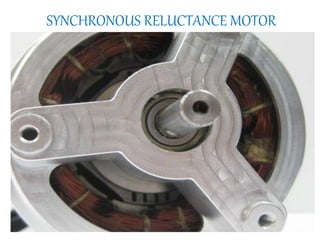
SYNCHRONUS RELUCTANCE MOTOR
Unit Syllabus
Constructional features, operating principle and
characteristics of synchronous reluctance motor
3. Reluctance Motors
• An induction motor with a modified squirrel-
cage rotor
– Single-phase or Three-phase
– rotor turns in synchronism with the rotating
magnetic flux
4. What is synchronous reluctance
motor?
• Stator consists of multiple salient (ie.
projecting) electromagnet poles, similar to a
wound field brushed DC motor
• Ferromagnetic rotor(non-permanent magnetic
poles)
• Torque is generated through the phenomenon
of magnetic reluctance.
• The rotor consists of soft magnetic material,
such as laminated silicon steel, which has
multiple projections acting as salient magnetic
poles through magnetic reluctance.
• Number of rotor poles is less than the number
of stator poles, which minimizes torque ripple.
13. Types of Rotor
Three different types of SynRM with anisotropic rotor structures
a) Simple salient pole (SP) rotor
b) Axially laminated rotor
c) Transversally laminated rotor
14. Simple salient pole (SP) rotor
• The salient pole rotor is
made by removing some
iron material in the
transversal region.
Four-pole conventional
salient pole design
15. Axially laminated rotor
• In the axially laminated rotor,
the laminations (iron) are
suitably shaped at each pole
and insulated from each
other using electrically and
magnetically passive
materials (insulation) and the
resulting stacks are
connected through pole
holders to the central region
to which the shaft is
connected. Four-pole axially-laminated
rotor design
16. Transversally laminated rotor
(Mostly Employed)
• In the third type of rotor
the laminations are
punched in the traditional
way. Thin ribs are left when
punching, thus the various
rotor segments are
connected to each other by
these ribs.
Four-pole transversally-laminated
rotor design
17. AXIAL TYPE RADIAL TYPE
Axially laminated rotor Radially laminated rotor
By increasing the Ld/Lq ratio, we
obtain more PF and efficiency
By decreasing Ld/Lq ratio,
circulating flux in the rotor pole
faces
Designed to have high saliency Designed to have optimized flux
guide
Offers good performance, torque,
PF, efficiency
To obtain less ripple torque, less
iron losses it is designed
Rotor has 2 designs Rotor has 1 design
Shaft may be rectangular cross
section
Shaft may be circular cross
section
High speed applications Poor choice for high speed
applications
18. Operating Principle
When a stator pole is energized, the rotor torque
is in the direction that will reduce reluctance.
Thus the nearest rotor pole is pulled into
alignment with the stator field (a position of less
reluctance).
In order to sustain rotation, the stator field must
rotate in advance of the rotor poles, thus
constantly "pulling" the rotor along.
19. Operation
• Rotor accelerates towards synchronous speed
• At a “critical” speed, the low-reluctance paths provided by
the salient poles will cause them to “snap” into
synchronism with the rotating flux.
20. Operation (continued)
• When the rotor synchronizes,
slip is equal to zero
• Rotor pulled around by
“reluctance torque”
• Figure at right shows the rotor
synchronized at no load
21. Operation (continued)
• A “step” increase in load
slows the rotor down, and
the rotor poles “lag” the
stator poles.
• The angle of lag, δ, is called
the “torque angle”.
• The maximum torque angle,
δmax = 45°.
22. Operation at maximum load
• Maximum load is when δ
= 45°.
• If load increases so that
δ>45°, the flux path is
“over stretched” and the
rotor falls out of
synchronism.
• Motor runs at slip speed
23. Reluctance torque, Trel
0
2
sin(2 )srel rel
V
T K
f
Trel = average value of reluctance torque
V = applied voltage (V)
f = line frequency (Hz)
δrel = torque angle (electrical degrees)
K = motor constant
25. Characteristics of synchronous
reluctance motor
The synchronous reluctance motor is not self
starting without the squirrel cage.
During run up it behaves as an induction
motor but as it approaches synchronous
speed, the reluctance torque takes over and
the motor locks into synchronous speed.
28. Advantage & Disadvantage of SyRM
Advantages of SyRM
1. There is no concern with demagnetization, hence
synchronous reluctance.
2. There need be no excitation field at zero torque, thus
eliminating electromagnetic spinning losses.
3. SyRM rotor can be constructed entirely from high
strength, low cost materials.
4. Lower torque ripple.
Disadvantages of SyRM
1. Compared to induction motor it is slightly heavier and
has low power factor.
2. High cost than induction motor.
3. Need speed synchronization to inverter output
frequency by using rotor position sensor and sensor less control.
29. Applications of syrm
1. Synthetic fiber manufacturing equipment
2. Wrapping and folding machine
3. Auxiliary time mechanism
4. Synchronized conveyors
5. Metering pumps