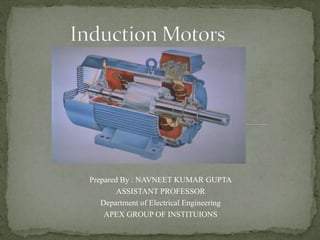
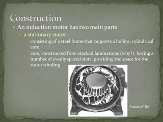
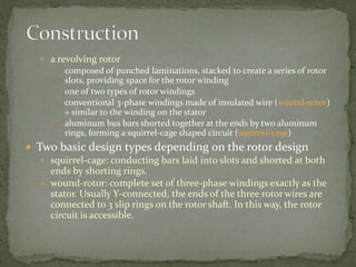
Prepared By : NAVNEET KUMAR GUPTA
ASSISTANT PROFESSOR
Department of Electrical Engineering
APEX GROUP OF INSTITUIONS
 Three-phase induction motors are the most common
and frequently encountered machines in industry
 simple design, rugged, low-price, easy maintenance
 wide range of power ratings: fractional horsepower to 10
MW
 run essentially as constant speed from no-load to full
load
 Its speed depends on the frequency of the power source
 not easy to have variable speed control
 requires a variable-frequency power-electronic drive for
optimal speed control
 An induction motor has two main parts
 a stationary stator
 consisting of a steel frame that supports a hollow, cylindrical
core
 core, constructed from stacked laminations (why?), having a
number of evenly spaced slots, providing the space for the
stator winding
Stator of IM
 a revolving rotor
 composed of punched laminations, stacked to create a series of rotor
slots, providing space for the rotor winding
 one of two types of rotor windings
 conventional 3-phase windings made of insulated wire (wound-rotor)
» similar to the winding on the stator
 aluminum bus bars shorted together at the ends by two aluminum
rings, forming a squirrel-cage shaped circuit (squirrel-cage)
 Two basic design types depending on the rotor design
 squirrel-cage: conducting bars laid into slots and shorted at both
ends by shorting rings.
 wound-rotor: complete set of three-phase windings exactly as the
stator. Usually Y-connected, the ends of the three rotor wires are
connected to 3 slip rings on the rotor shaft. In this way, the rotor
circuit is accessible.
Squirrel cage rotor
Wound rotor
Notice the
slip rings
Cutaway in a
typical wound-
rotor IM.
Notice the
brushes and the
slip rings
Brushes
Slip rings
 Balanced three phase windings, i.e.
mechanically displaced 120 degrees
form each other, fed by balanced
three phase source
 A rotating magnetic field with
constant magnitude is produced,
rotating with a speed
Where fe is the supply frequency and
P is the no. of poles and nsync is called
the synchronous speed in rpm
(revolutions per minute)
120 e
sync
f
n rpm
P

 This rotating magnetic field cuts the rotor windings and
produces an induced voltage in the rotor windings
 Due to the fact that the rotor windings are short circuited, for
both squirrel cage and wound-rotor, and induced current flows
in the rotor windings
 The rotor current produces another magnetic field
 A torque is produced as a result of the interaction of those two
magnetic fields
Where ind is the induced torque and BR and BS are the magnetic
flux densities of the rotor and the stator respectively
ind R s
kB B
  
 At what speed will the IM run?
 Can the IM run at the synchronous speed, why?
 If rotor runs at the synchronous speed, which is the
same speed of the rotating magnetic field, then the rotor
will appear stationary to the rotating magnetic field and
the rotating magnetic field will not cut the rotor. So, no
induced current will flow in the rotor and no rotor
magnetic flux will be produced so no torque is
generated and the rotor speed will fall below the
synchronous speed
 When the speed falls, the rotating magnetic field will
cut the rotor windings and a torque is produced
 So, the IM will always run at a speed lower than the
synchronous speed
 The difference between the motor speed and the
synchronous speed is called the Slip
Where nslip= slip speed
nsync= speed of the magnetic field
nm = mechanical shaft speed of the motor
slip sync m
n n n
 
Typical torque-speed characteristics of induction motor
 The induced torque is zero at synchronous speed.
Discussed earlier.
 The curve is nearly linear between no-load and full
load. In this range, the rotor resistance is much
greater than the reactance, so the rotor current,
torque increase linearly with the slip.
 There is a maximum possible torque that can’t be
exceeded. This torque is called pullout torque and is 2
to 3 times the rated full-load torque.
 The starting torque of the motor is slightly higher
than its full-load torque, so the motor will start
carrying any load it can supply at full load.
 The torque of the motor for a given slip varies as the
square of the applied voltage.
 If the rotor is driven faster than synchronous speed it
will run as a generator, converting mechanical
power to electric power.
 Maximum torque occurs when the power transferred to R2/s is
maximum.
 This condition occurs when R2/s equals the magnitude of the
impedance RTH + j (XTH + X2)

Induction Machines.ppt

  • 1.
    Prepared By :NAVNEET KUMAR GUPTA ASSISTANT PROFESSOR Department of Electrical Engineering APEX GROUP OF INSTITUIONS
  • 2.
     Three-phase inductionmotors are the most common and frequently encountered machines in industry  simple design, rugged, low-price, easy maintenance  wide range of power ratings: fractional horsepower to 10 MW  run essentially as constant speed from no-load to full load  Its speed depends on the frequency of the power source  not easy to have variable speed control  requires a variable-frequency power-electronic drive for optimal speed control
  • 3.
     An inductionmotor has two main parts  a stationary stator  consisting of a steel frame that supports a hollow, cylindrical core  core, constructed from stacked laminations (why?), having a number of evenly spaced slots, providing the space for the stator winding Stator of IM
  • 4.
     a revolvingrotor  composed of punched laminations, stacked to create a series of rotor slots, providing space for the rotor winding  one of two types of rotor windings  conventional 3-phase windings made of insulated wire (wound-rotor) » similar to the winding on the stator  aluminum bus bars shorted together at the ends by two aluminum rings, forming a squirrel-cage shaped circuit (squirrel-cage)  Two basic design types depending on the rotor design  squirrel-cage: conducting bars laid into slots and shorted at both ends by shorting rings.  wound-rotor: complete set of three-phase windings exactly as the stator. Usually Y-connected, the ends of the three rotor wires are connected to 3 slip rings on the rotor shaft. In this way, the rotor circuit is accessible.
  • 5.
    Squirrel cage rotor Woundrotor Notice the slip rings
  • 6.
    Cutaway in a typicalwound- rotor IM. Notice the brushes and the slip rings Brushes Slip rings
  • 7.
     Balanced threephase windings, i.e. mechanically displaced 120 degrees form each other, fed by balanced three phase source  A rotating magnetic field with constant magnitude is produced, rotating with a speed Where fe is the supply frequency and P is the no. of poles and nsync is called the synchronous speed in rpm (revolutions per minute) 120 e sync f n rpm P 
  • 8.
     This rotatingmagnetic field cuts the rotor windings and produces an induced voltage in the rotor windings  Due to the fact that the rotor windings are short circuited, for both squirrel cage and wound-rotor, and induced current flows in the rotor windings  The rotor current produces another magnetic field  A torque is produced as a result of the interaction of those two magnetic fields Where ind is the induced torque and BR and BS are the magnetic flux densities of the rotor and the stator respectively ind R s kB B   
  • 9.
     At whatspeed will the IM run?  Can the IM run at the synchronous speed, why?  If rotor runs at the synchronous speed, which is the same speed of the rotating magnetic field, then the rotor will appear stationary to the rotating magnetic field and the rotating magnetic field will not cut the rotor. So, no induced current will flow in the rotor and no rotor magnetic flux will be produced so no torque is generated and the rotor speed will fall below the synchronous speed  When the speed falls, the rotating magnetic field will cut the rotor windings and a torque is produced
  • 10.
     So, theIM will always run at a speed lower than the synchronous speed  The difference between the motor speed and the synchronous speed is called the Slip Where nslip= slip speed nsync= speed of the magnetic field nm = mechanical shaft speed of the motor slip sync m n n n  
  • 11.
  • 12.
     The inducedtorque is zero at synchronous speed. Discussed earlier.  The curve is nearly linear between no-load and full load. In this range, the rotor resistance is much greater than the reactance, so the rotor current, torque increase linearly with the slip.  There is a maximum possible torque that can’t be exceeded. This torque is called pullout torque and is 2 to 3 times the rated full-load torque.
  • 13.
     The startingtorque of the motor is slightly higher than its full-load torque, so the motor will start carrying any load it can supply at full load.  The torque of the motor for a given slip varies as the square of the applied voltage.  If the rotor is driven faster than synchronous speed it will run as a generator, converting mechanical power to electric power.
  • 15.
     Maximum torqueoccurs when the power transferred to R2/s is maximum.  This condition occurs when R2/s equals the magnitude of the impedance RTH + j (XTH + X2)