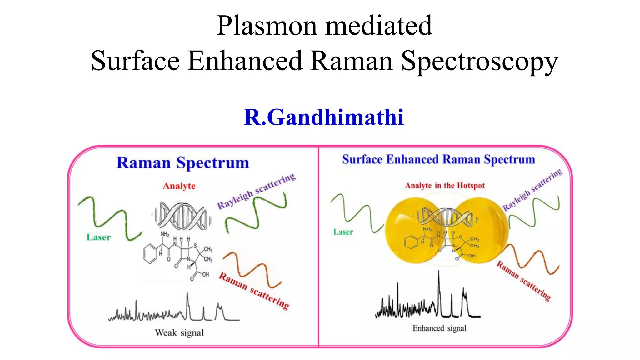
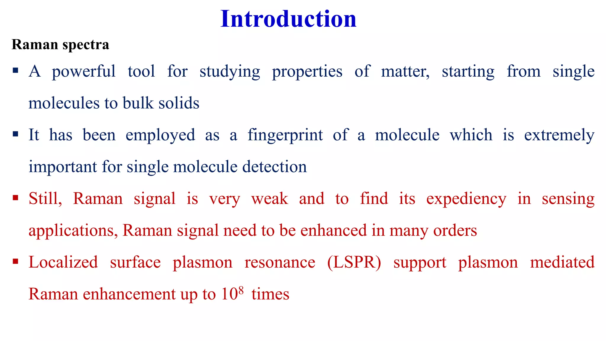
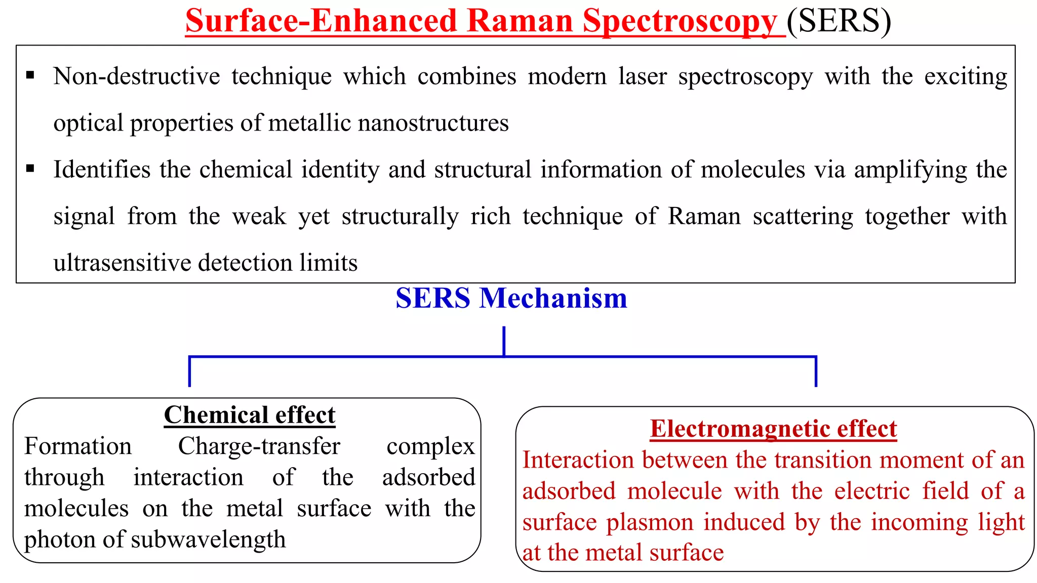
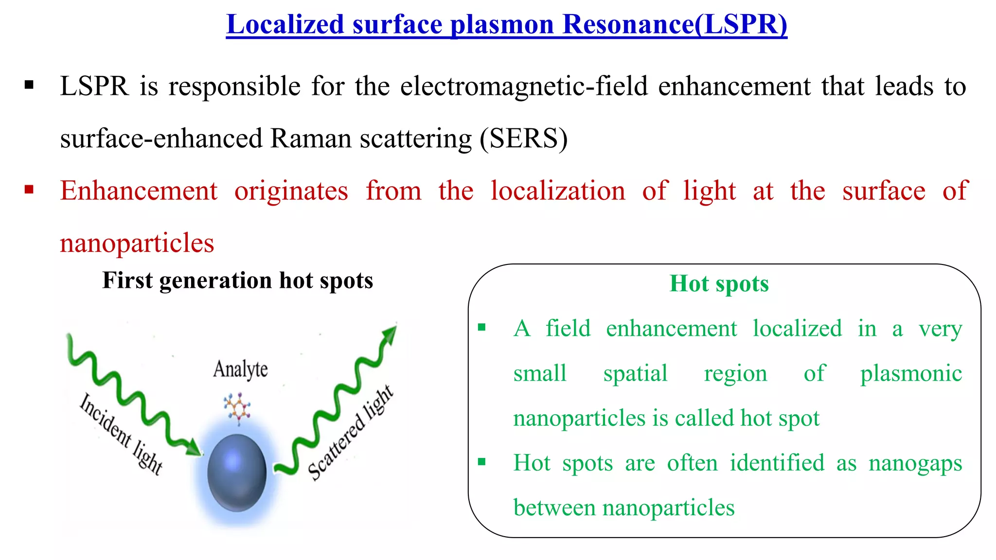
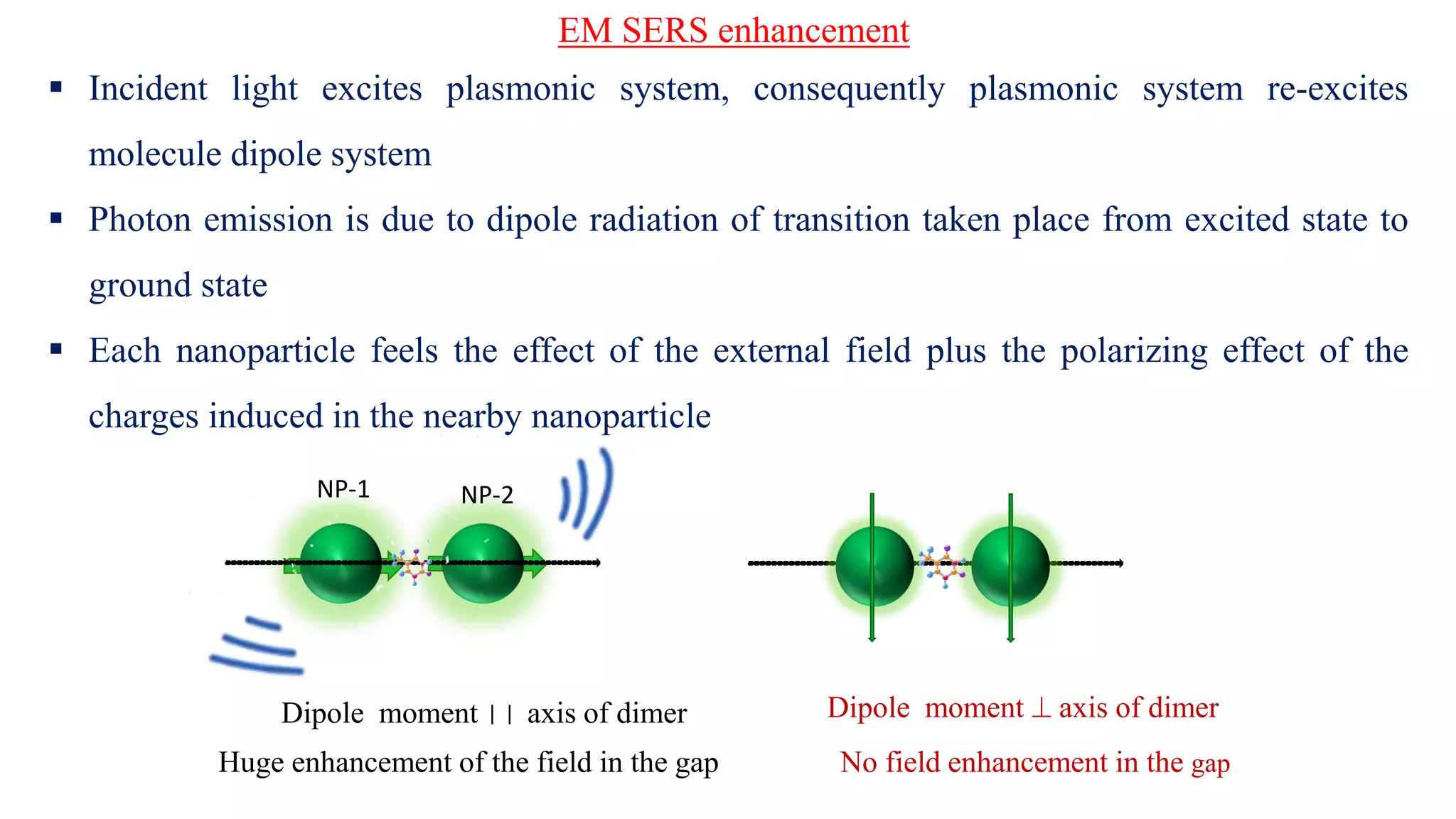
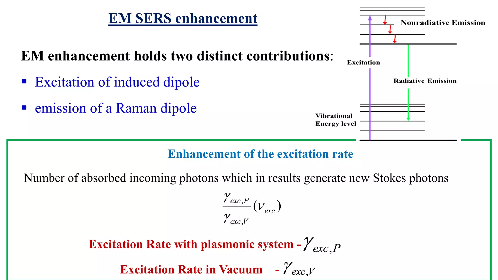
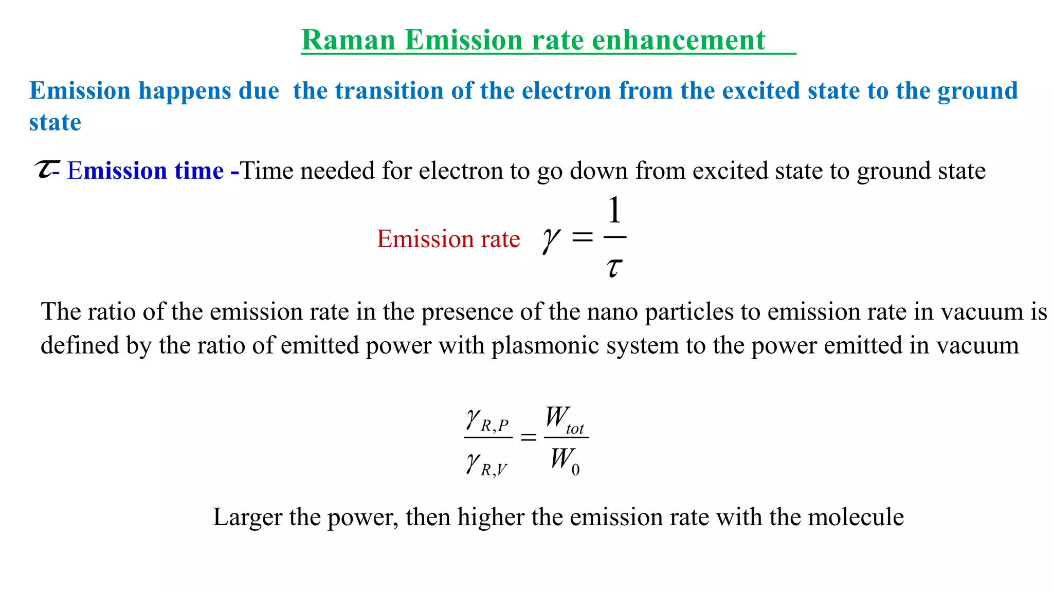
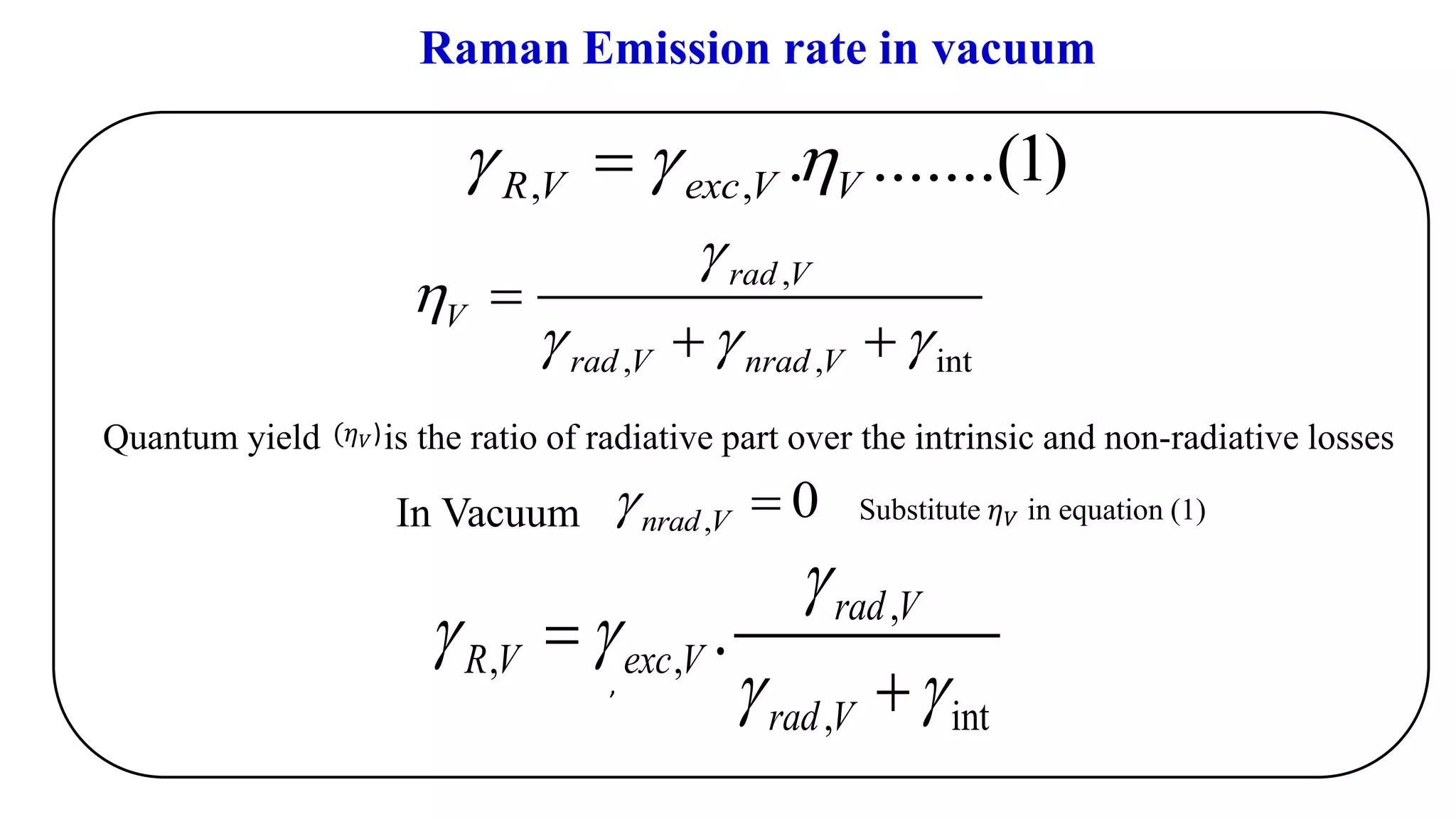
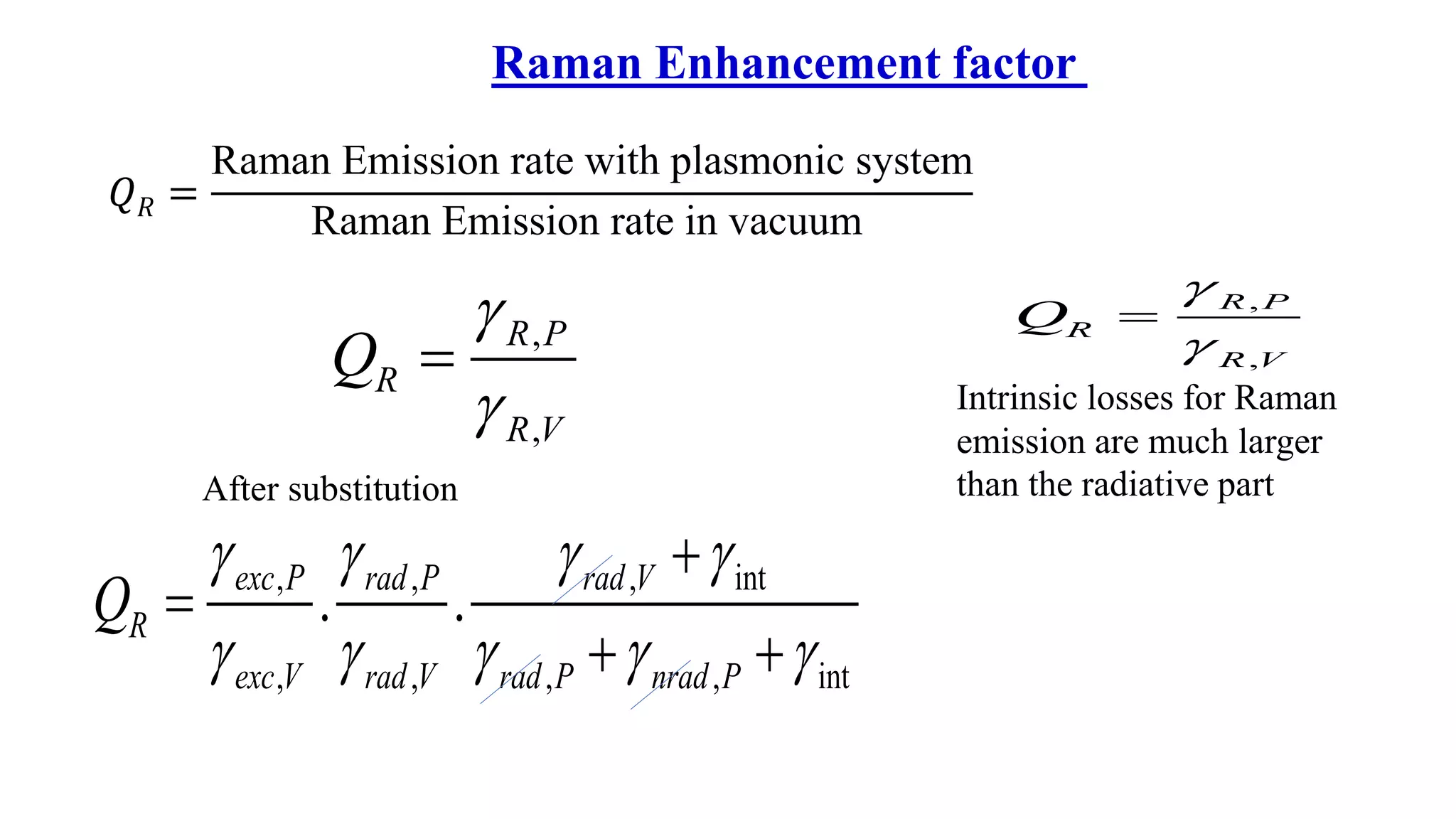
R.Gandhimathi
Plasmon mediated
Surface Enhanced Raman Spectroscopy
Raman spectra
▪ A powerful tool for studying properties of matter, starting from single
molecules to bulk solids
▪ It has been employed as a fingerprint of a molecule which is extremely
important for single molecule detection
▪ Still, Raman signal is very weak and to find its expediency in sensing
applications, Raman signal need to be enhanced in many orders
▪ Localized surface plasmon resonance (LSPR) support plasmon mediated
Raman enhancement up to 108 times
Introduction
Raman Shift vs Intensity
Raman spectroscopy
• Raman Shift: Frequency difference of
the inelastically scattered radiation from
the incident beam
• It gives vibrational energies of the
molecule
When the light beam is deflected by a molecule, wavelength of incident light
changes. i.e. An optical transition occurs when light is inelastically scattered
by a target molecule
Raman scattering
0
dP
dQ

▪ In Raman scattering, the molecular vibration
changes the polarizability upon excitation.
Induced dipole P = α E,
α - the polarizability of the molecule
(Q is the normal coordinate of the vibration)
▪ Thus it identifies vibrational, & rotational
modes of molecules via the light-matter
interaction
One photon decompose
into two photons
0exc s  = +
-vibrational energy of the molecule0
Energy increase/decrease is related to the vibrational energy spacing in the ground state
Stokes & Anti-stokes lines
▪ Non-destructive technique which combines modern laser spectroscopy with the exciting
optical properties of metallic nanostructures
▪ Identifies the chemical identity and structural information of molecules via amplifying the
signal from the weak yet structurally rich technique of Raman scattering together with
ultrasensitive detection limits
Surface-Enhanced Raman Spectroscopy (SERS)
SERS Mechanism
Chemical effect
Formation Charge‐transfer complex
through interaction of the adsorbed
molecules on the metal surface with the
photon of subwavelength
Electromagnetic effect
Interaction between the transition moment of an
adsorbed molecule with the electric field of a
surface plasmon induced by the incoming light
at the metal surface
▪ LSPR is responsible for the electromagnetic-field enhancement that leads to
surface-enhanced Raman scattering (SERS)
▪ Enhancement originates from the localization of light at the surface of
nanoparticles
First generation hot spots Hot spots
▪ A field enhancement localized in a very
small spatial region of plasmonic
nanoparticles is called hot spot
▪ Hot spots are often identified as nanogaps
between nanoparticles
Localized surface plasmon Resonance(LSPR)
Enhancement of Raman scattering with plasmonic system
▪ Local electromagnetic field in the gap is
extremely intense because of the strong
electromagnetic coupling
▪ Mutual excitation from the metal NP system
via enhanced induced dipole results in
enhanced apparent Raman polarizability of
adsorbed molecule
The presence of the metallic structure nearby the molecule modifies the
efficiency with which the molecule radiates Raman power
▪ Incident light excites plasmonic system, consequently plasmonic system re-excites
molecule dipole system
▪ Photon emission is due to dipole radiation of transition taken place from excited state to
ground state
▪ Each nanoparticle feels the effect of the external field plus the polarizing effect of the
charges induced in the nearby nanoparticle
Dipole moment ⊥ axis of dimerDipole moment   axis of dimer
Huge enhancement of the field in the gap No field enhancement in the gap
NP-1 NP-2
EM SERS enhancement
EM enhancement holds two distinct contributions:
▪ Excitation of induced dipole
▪ emission of a Raman dipole
Number of absorbed incoming photons which in results generate new Stokes photons
,
,
( )exc P
exc
exc V



,exc PExcitation Rate with plasmonic system -
Excitation Rate in Vacuum - ,exc V
Enhancement of the excitation rate
EM SERS enhancement
,
, 0
R P tot
R V
W
W


=
The ratio of the emission rate in the presence of the nano particles to emission rate in vacuum is
defined by the ratio of emitted power with plasmonic system to the power emitted in vacuum
Larger the power, then higher the emission rate with the molecule
Emission happens due the transition of the electron from the excited state to the ground
state
Emission rate
- Emission time -Time needed for electron to go down from excited state to ground state
1


=
Raman Emission rate enhancement
In Vacuum
,
, , int
rad V
V
rad V nrad V


  
=
+ +
, , . .......(1)R V exc V V  =
,
by
Substitute 𝜂 𝑉 in equation (1)
Quantum yield is the ratio of radiative part over the intrinsic and non-radiative losses(𝜂 𝑉)
,
, ,
, int
. rad V
R V exc V
rad V

 
 
=
+
Raman Emission rate in vacuum
, 0nrad V =
Substitute 𝜂 𝑃 in equation (2)
,
, , int
rad P
P
rad P nrad P


  
=
+ +
where
𝜂 𝑃- Quantum efficiency with plasmonic system
Radiative, Non Radiative emission rate,
-Intrinsic losses
Raman Emission rate with the presence of metal nano particle
,
, , int
rad P
P
rad P nrad P


  
=
+ +
Emission rate is obtained by considering both radiative and non radiative emissions
, , . .......(2)R P exc P P  =
,nrad P,rad P
int
𝑄 𝑅 =
Raman Emission rate with plasmonic system
Raman Emission rate in vacuum
,
,
R P
R
R V
Q


=
After substitution
, , , int
, , , , int
. .exc P rad P rad V
R
exc V rad V rad P nrad P
Q
   
    
+
=
+ +
Intrinsic losses for Raman
emission are much larger
than the radiative part
,
,
R P
R
R V
Q


=
Raman Enhancement factor
, ,
, ,
.exc P rad P
exc V rad V
 
 
=
, , int
, , int
. .exc P rad P
R
exc V rad V
Q
  
  
=
QR=An excitation local field enhancement  a radiation local field enhancement
Only enhancement of radiation emission and no more quantum yield
i.e. No quenching
, ,
, ,
( ). ( )exc P rad P
R exc s
exc V rad V
Q
 
 
 
=SERS Enhancement factor
,2
,
( ). ( )rad P
R exc s
rad V
Q FE

 

=
Average Enhancement factor
ℏ0 < ℏ 𝑠
h0 is much smaller
than the Stokes or
excitation photon
energy
,2
,
( ) exc P
exc
exc V
FE



=
= Excitation enhancement𝐹𝐸2( 𝑒𝑥𝑐)
field enhancement factor at the Stokes frequency)𝐹𝐸2( 𝑠
,2
,
( ) rad P
s
rad V
FE



=
s exc 2 2 4
( ). ( ) ( )R exc s excQ FE FE FE  = = since
▪ Field enhancement factor in the order of 104
▪ Average SERS intensities from coupled plasmonic nanostructures  four
orders of magnitude
▪ Raman spectroscopy is a prevailing vibrational spectroscopy technique, provides the
structural information of molecules. However, compared to the Fluorescence Emission
process, Raman Emission is a very weak process
▪ In SERS, Raman scattering generated by molecules is strongly amplified by placing
them in the vicinity of plasmonic nano structures. Enhancement is obtained by coupling
of the incident and Raman EM fields on metallic surfaces with localized surface-plasmon
resonances
▪ Intense plasmonic hotspots associated with the metallic nanostructures enhance the
sensing capabilities by a factor up to 1011 and permit to observe individual molecules
Summary
References
1. Yuko S. Yamamotoa,b, Yukihiro Ozakic,∗, Tamitake Itohd, ReviewRecent progress and frontiers in the
electromagnetic mechanism ofsurface-enhanced Raman scattering”, Journal of Photochemistry and
Photobiology C:2014
2. Song-Yuan Ding1, Jun Yi1, Jian-Feng Li1,2, Bin Ren1,2, De-Yin Wu1, Rajapandiyan Panneerselvam1
and Zhong-Qun Tian1, “Nanostructure-based plasmon-enhanced Raman spectroscopy for surface analysis
of materials “
3. John Henson, Anirban Bhattacharyya, Theodore D. Moustakas, and Roberto Paiella, “Controlling the
recombination rate of semiconductor active layers via coupling to dispersion-engineered surface
plasmons”, J. Opt. Soc. Am. B/Vol. 25, No. 8/August 2008
4. Guo Xia 1,*, Cuixia Zhou 1, Shiqun Jin 1, Chan Huang 2,3,4, Jinyu Xing 5 and Zhijian Liu, Sensitivity
Enhancement of Two-Dimensional Materials Based on Genetic Optimization in Surface Plasmon
Resonance, Sensors 2019, 19, 1198;
Tak you

Surface Enhanced Raman Spectroscopy

  • 1.
  • 2.
    Raman spectra ▪ Apowerful tool for studying properties of matter, starting from single molecules to bulk solids ▪ It has been employed as a fingerprint of a molecule which is extremely important for single molecule detection ▪ Still, Raman signal is very weak and to find its expediency in sensing applications, Raman signal need to be enhanced in many orders ▪ Localized surface plasmon resonance (LSPR) support plasmon mediated Raman enhancement up to 108 times Introduction
  • 3.
    Raman Shift vsIntensity Raman spectroscopy • Raman Shift: Frequency difference of the inelastically scattered radiation from the incident beam • It gives vibrational energies of the molecule When the light beam is deflected by a molecule, wavelength of incident light changes. i.e. An optical transition occurs when light is inelastically scattered by a target molecule
  • 4.
    Raman scattering 0 dP dQ  ▪ InRaman scattering, the molecular vibration changes the polarizability upon excitation. Induced dipole P = α E, α - the polarizability of the molecule (Q is the normal coordinate of the vibration) ▪ Thus it identifies vibrational, & rotational modes of molecules via the light-matter interaction One photon decompose into two photons 0exc s  = + -vibrational energy of the molecule0
  • 5.
    Energy increase/decrease isrelated to the vibrational energy spacing in the ground state Stokes & Anti-stokes lines
  • 6.
    ▪ Non-destructive techniquewhich combines modern laser spectroscopy with the exciting optical properties of metallic nanostructures ▪ Identifies the chemical identity and structural information of molecules via amplifying the signal from the weak yet structurally rich technique of Raman scattering together with ultrasensitive detection limits Surface-Enhanced Raman Spectroscopy (SERS) SERS Mechanism Chemical effect Formation Charge‐transfer complex through interaction of the adsorbed molecules on the metal surface with the photon of subwavelength Electromagnetic effect Interaction between the transition moment of an adsorbed molecule with the electric field of a surface plasmon induced by the incoming light at the metal surface
  • 7.
    ▪ LSPR isresponsible for the electromagnetic-field enhancement that leads to surface-enhanced Raman scattering (SERS) ▪ Enhancement originates from the localization of light at the surface of nanoparticles First generation hot spots Hot spots ▪ A field enhancement localized in a very small spatial region of plasmonic nanoparticles is called hot spot ▪ Hot spots are often identified as nanogaps between nanoparticles Localized surface plasmon Resonance(LSPR)
  • 8.
    Enhancement of Ramanscattering with plasmonic system ▪ Local electromagnetic field in the gap is extremely intense because of the strong electromagnetic coupling ▪ Mutual excitation from the metal NP system via enhanced induced dipole results in enhanced apparent Raman polarizability of adsorbed molecule The presence of the metallic structure nearby the molecule modifies the efficiency with which the molecule radiates Raman power
  • 9.
    ▪ Incident lightexcites plasmonic system, consequently plasmonic system re-excites molecule dipole system ▪ Photon emission is due to dipole radiation of transition taken place from excited state to ground state ▪ Each nanoparticle feels the effect of the external field plus the polarizing effect of the charges induced in the nearby nanoparticle Dipole moment ⊥ axis of dimerDipole moment   axis of dimer Huge enhancement of the field in the gap No field enhancement in the gap NP-1 NP-2 EM SERS enhancement
  • 10.
    EM enhancement holdstwo distinct contributions: ▪ Excitation of induced dipole ▪ emission of a Raman dipole Number of absorbed incoming photons which in results generate new Stokes photons , , ( )exc P exc exc V    ,exc PExcitation Rate with plasmonic system - Excitation Rate in Vacuum - ,exc V Enhancement of the excitation rate EM SERS enhancement
  • 11.
    , , 0 R Ptot R V W W   = The ratio of the emission rate in the presence of the nano particles to emission rate in vacuum is defined by the ratio of emitted power with plasmonic system to the power emitted in vacuum Larger the power, then higher the emission rate with the molecule Emission happens due the transition of the electron from the excited state to the ground state Emission rate - Emission time -Time needed for electron to go down from excited state to ground state 1   = Raman Emission rate enhancement
  • 12.
    In Vacuum , , ,int rad V V rad V nrad V      = + + , , . .......(1)R V exc V V  = , by Substitute 𝜂 𝑉 in equation (1) Quantum yield is the ratio of radiative part over the intrinsic and non-radiative losses(𝜂 𝑉) , , , , int . rad V R V exc V rad V      = + Raman Emission rate in vacuum , 0nrad V =
  • 13.
    Substitute 𝜂 𝑃in equation (2) , , , int rad P P rad P nrad P      = + + where 𝜂 𝑃- Quantum efficiency with plasmonic system Radiative, Non Radiative emission rate, -Intrinsic losses Raman Emission rate with the presence of metal nano particle , , , int rad P P rad P nrad P      = + + Emission rate is obtained by considering both radiative and non radiative emissions , , . .......(2)R P exc P P  = ,nrad P,rad P int
  • 14.
    𝑄 𝑅 = RamanEmission rate with plasmonic system Raman Emission rate in vacuum , , R P R R V Q   = After substitution , , , int , , , , int . .exc P rad P rad V R exc V rad V rad P nrad P Q          + = + + Intrinsic losses for Raman emission are much larger than the radiative part , , R P R R V Q   = Raman Enhancement factor
  • 15.
    , , , , .excP rad P exc V rad V     = , , int , , int . .exc P rad P R exc V rad V Q       = QR=An excitation local field enhancement  a radiation local field enhancement Only enhancement of radiation emission and no more quantum yield i.e. No quenching , , , , ( ). ( )exc P rad P R exc s exc V rad V Q       =SERS Enhancement factor
  • 16.
    ,2 , ( ). ()rad P R exc s rad V Q FE     = Average Enhancement factor ℏ0 < ℏ 𝑠 h0 is much smaller than the Stokes or excitation photon energy ,2 , ( ) exc P exc exc V FE    = = Excitation enhancement𝐹𝐸2( 𝑒𝑥𝑐) field enhancement factor at the Stokes frequency)𝐹𝐸2( 𝑠 ,2 , ( ) rad P s rad V FE    = s exc 2 2 4 ( ). ( ) ( )R exc s excQ FE FE FE  = = since ▪ Field enhancement factor in the order of 104 ▪ Average SERS intensities from coupled plasmonic nanostructures  four orders of magnitude
  • 17.
    ▪ Raman spectroscopyis a prevailing vibrational spectroscopy technique, provides the structural information of molecules. However, compared to the Fluorescence Emission process, Raman Emission is a very weak process ▪ In SERS, Raman scattering generated by molecules is strongly amplified by placing them in the vicinity of plasmonic nano structures. Enhancement is obtained by coupling of the incident and Raman EM fields on metallic surfaces with localized surface-plasmon resonances ▪ Intense plasmonic hotspots associated with the metallic nanostructures enhance the sensing capabilities by a factor up to 1011 and permit to observe individual molecules Summary
  • 18.
    References 1. Yuko S.Yamamotoa,b, Yukihiro Ozakic,∗, Tamitake Itohd, ReviewRecent progress and frontiers in the electromagnetic mechanism ofsurface-enhanced Raman scattering”, Journal of Photochemistry and Photobiology C:2014 2. Song-Yuan Ding1, Jun Yi1, Jian-Feng Li1,2, Bin Ren1,2, De-Yin Wu1, Rajapandiyan Panneerselvam1 and Zhong-Qun Tian1, “Nanostructure-based plasmon-enhanced Raman spectroscopy for surface analysis of materials “ 3. John Henson, Anirban Bhattacharyya, Theodore D. Moustakas, and Roberto Paiella, “Controlling the recombination rate of semiconductor active layers via coupling to dispersion-engineered surface plasmons”, J. Opt. Soc. Am. B/Vol. 25, No. 8/August 2008 4. Guo Xia 1,*, Cuixia Zhou 1, Shiqun Jin 1, Chan Huang 2,3,4, Jinyu Xing 5 and Zhijian Liu, Sensitivity Enhancement of Two-Dimensional Materials Based on Genetic Optimization in Surface Plasmon Resonance, Sensors 2019, 19, 1198;
  • 19.