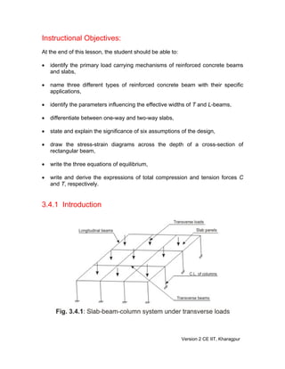
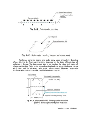
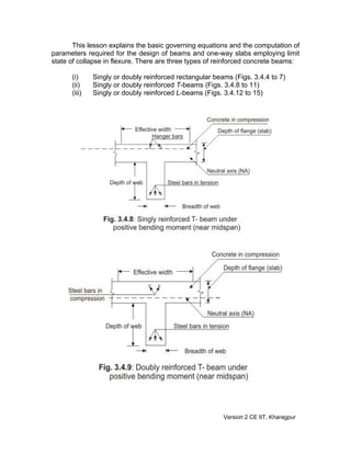
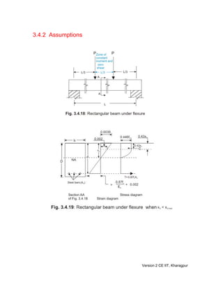
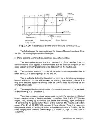
SlideShare a Scribd company logo
Module
3
Limit State of Collapse -
Flexure (Theories and
Examples)
Version 2 CE IIT, Kharagpur
Lesson
4
Computation of
Parameters of
Governing Equations
Version 2 CE IIT, Kharagpur
Instructional Objectives:
At the end of this lesson, the student should be able to:
• identify the primary load carrying mechanisms of reinforced concrete beams
and slabs,
• name three different types of reinforced concrete beam with their specific
applications,
• identify the parameters influencing the effective widths of T and L-beams,
• differentiate between one-way and two-way slabs,
• state and explain the significance of six assumptions of the design,
• draw the stress-strain diagrams across the depth of a cross-section of
rectangular beam,
• write the three equations of equilibrium,
• write and derive the expressions of total compression and tension forces C
and T, respectively.
3.4.1 Introduction
Version 2 CE IIT, Kharagpur
Reinforced concrete beams and slabs carry loads primarily by bending
(Figs. 3.4.1 to 3). They are, therefore, designed on the basis of limit state of
collapse in flexure. The beams are also to be checked for other limit states of
shear and torsion. Slabs under normal design loadings (except in bridge decks
etc.) need not be provided with shear reinforcement. However, adequate
torsional reinforcement must be provided wherever needed.
Version 2 CE IIT, Kharagpur
This lesson explains the basic governing equations and the computation of
parameters required for the design of beams and one-way slabs employing limit
state of collapse in flexure. There are three types of reinforced concrete beams:
(i) Singly or doubly reinforced rectangular beams (Figs. 3.4.4 to 7)
(ii) Singly or doubly reinforced T-beams (Figs. 3.4.8 to 11)
(iii) Singly or doubly reinforced L-beams (Figs. 3.4.12 to 15)
Version 2 CE IIT, Kharagpur
During construction of reinforced concrete structures, concrete slabs and beams
are cast monolithic making the beams a part of the floor deck system. While
bending under positive moments near midspan, bending compression stresses at
the top are taken by the rectangular section of the beams above the neutral axis
and the slabs, if present in T or L-beams (Figs. 3.4.4, 5, 8, 9, 12 and 13).
However, under the negative moment over the support or elsewhere, the bending
compression stresses are at the bottom and the rectangular sections of
rectangular, T and L-beams below the neutral axis only resist that compression
(Figs. 3.4.6, 7, 10, 11, 14 and 15). Thus, in a slab-beam system the beam will be
Version 2 CE IIT, Kharagpur
considered as rectangular for the negative moment and T for the positive
moment. While for the intermediate spans of slabs the beam under positive
moment is considered as T, the end span edge beam is considered as L-beam if
the slab is not projected on both the sides of the beam. It is worth mentioning that
the effective width of flange of these T or L-beams is to be determined which
depends on:
Version 2 CE IIT, Kharagpur
(a) if it is an isolated or continuous beam
(b) the distance between points of zero moments in the beam
(c) the width of the web
(d) the thickness of the flange
Reinforced concrete slabs are classified as one-way or two-way
depending on if they are spanning in one or two directions (Figs. 3.4.16 and 17).
As a guideline, slabs whose ratio of longer span (ly) to the shorter span (lx) is
more than two are considered as one-way slabs. One-way slabs also can be
designed following the procedure of the design of beams of rectangular cross-
section. Again, slabs may be isolated or continuous also.
Version 2 CE IIT, Kharagpur
3.4.2 Assumptions
Version 2 CE IIT, Kharagpur
The following are the assumptions of the design of flexural members (Figs.
3.4.18 to 20) employing limit state of collapse:
(i) Plane sections normal to the axis remain plane after bending.
This assumption ensures that the cross-section of the member does not
warp due to the loads applied. It further means that the strain at any point on the
cross-section is directly proportional to its distance from the neutral axis.
(ii) The maximum strain in concrete at the outer most compression fibre is
taken as 0.0035 in bending (Figs. 3.4.19 and 20).
This is a clearly defined limiting strain of concrete in bending compression
beyond which the concrete will be taken as reaching the state of collapse. It is
very clear that the specified limiting strain of 0.0035 does not depend on the
strength of concrete.
(iii) The acceptable stress-strain curve of concrete is assumed to be parabolic
as shown in Fig. 1.2.1 of Lesson 2.
The maximum compressive stress-strain curve in the structure is obtained
by reducing the values of the top parabolic curve (Figs. 21 of IS 456:2000) in two
stages. First, dividing by 1.5 due to size effect and secondly, again dividing by
1.5 considering the partial safety factor of the material. The middle and bottom
curves (Fig. 21 of IS 456:2000) represent these stages. Thus, the maximum
compressive stress in bending is limited to the constant value of 0.446 fck for the
strain ranging from 0.002 to 0.0035 (Figs. 3.4.19 and 20, Figs. 21 and 22 of IS
456:2000).
Version 2 CE IIT, Kharagpur
(iv) The tensile strength of concrete is ignored.
Concrete has some tensile strength (very small but not zero). Yet, this
tensile strength is ignored and the steel reinforcement is assumed to resist the
tensile stress. However, the tensile strength of concrete is taken into account to
check the deflection and crack widths in the limit state of serviceability.
(v) The design stresses of the reinforcement are derived from the
representative stress-strain curves as shown in Figs. 1.2.3 and 4 of Lesson 2 and
Figs. 23A and B of IS 456:2000, for the type of steel used using the partial safety
factor γm as 1.15.
In the reinforced concrete structures, two types of steel are used: one with
definite yield point (mild steel, Figs. 1.2.3 of Lesson 2 and Figs. 23B of IS
456:2000) and the other where the yield points are not definite (cold work
deformed bars). The representative stress-strain diagram (Fig. 1.2.4 of Lesson 2
and Fig. 23A of IS 456:2000) defines the points between 0.8 fy and 1.0 fy in case
of cold work deformed bars where the curve is inelastic.
(vi) The maximum strain in the tension reinforcement in the section at failure
shall not be less than fy/(1.15 Es) + 0.002, where fy is the characteristic strength
of steel and Es = modulus of elasticity of steel (Figs. 3.4.19 and 20).
This assumption ensures ductile failure in which the tensile reinforcement
undergoes a certain degree of inelastic deformation before concrete fails in
compression.
3.4.3 Singly Reinforce Rectangular Beams
Figure 3.4.18 shows the singly reinforced rectangular beam in flexure. The
following notations are used (Figs. 3.4.19 and 20):
Ast = area of tension steel
b = width of the beam
C = total compressive force of concrete
d = effective depth of the beam
L = centre to centre distance between supports
P = two constant loads acting at a distance of L/3 from the two supports
of the beam
T = total tensile force of steel
xu = depth of neutral axis from the top compression fibre
3.4.4 Equations of Equilibrium
The cross-sections of the beam under the applied loads as shown in Fig.
3.4.18 has three types of combinations of shear forces and bending moments: (i)
Version 2 CE IIT, Kharagpur
only shear force is there at the support and bending moment is zero, (ii) both
bending moment (increasing gradually) and shear force (constant = P) are there
between the support and the loading point and (iii) a constant moment (= PL/3) is
there in the middle third zone i.e. between the two loads where the shear force is
zero (Fig. 1.1.1 of Lesson 1). Since the beam is in static equilibrium, any cross-
section of the beam is also in static equilibrium. Considering the cross-section in
the middle zone (Fig. 3.4.18) the three equations of equilibrium are the following
(Figs. 3.4.19 and 20):
(i) Equilibrium of horizontal forces: Σ H = 0 gives T = C
(3.1)
(ii) Equilibrium of vertical shear forces: Σ V = 0
(3.2)
This equation gives an identity 0 = 0 as there is no shear in the middle
third zone of the beam.
(iii) Equilibrium of moments: Σ M = 0,
(3.3)
This equation shows that the applied moment at the section is fully resisted by
moment of the resisting couple T a = C a , where a is the operating lever arm
between T and C (Figs. 3.4.19 and 20).
3.4.5 Computations of C and T
Version 2 CE IIT, Kharagpur
Figures 3.4.21a and b present the enlarged view of the compressive part
of the strain and stress diagrams. The convex parabolic part of the stress block of
Fig. 3.4.21b is made rectangular by dotted lines to facilitate the calculations
adding another concave parabolic stress zone which is really non-existent as
marked by hatch in Fig. 3.4.21b.
The different compressive forces C, C1, C2 and C3 and distances x1 to x5
and xu as marked in Fig. 3.4.21b are explained in the following:
C = Total compressive force of concrete = C1 + C2
C1 = Compressive force of concrete due to the constant stress of 0.446
fck and up to a depth of x3 from the top fibre
C2 = Compressive force of concrete due to the convex parabolic stress
block of values ranging from zero at the neutral axis to 0.446 fck at a
distance of x3 from the top fibre
C3 = Compressive force of concrete due to the concave parabolic stress
block (actually non-existent) of values ranging from 0.446 fck at the
neutral axis to zero at a distance of x3 from the top fibre
x1 = Distance of the line of action of C1 from the top compressive fibre
x2 = Distance of the line of action of C (= C1 + C2) from the top
compressive fibre
x3 = Distance of the fibre from the top compressive fibre, where the strain
= 0.002 and stress = 0.446 fck
x4 = Distance of the line of action of C2 from the top compressive fibre
x5 = Distance of the line of action of C3 from the top compressive fibre
xu = Distance of the neutral axis from the top compressive fibre.
From the strain triangle of Fig. 3.4.21a, we have
570
7
4
00350
00203 .
.
.
x
xx
u
u ===
−
, giving
x3 = 0.43 xu
(3.4)
Since C1 is due to the constant stress acting from the top to a distance of x3, the
distance x1 of the line of action of C1 is:
Version 2 CE IIT, Kharagpur
x1 = 0.5 x3 = 0.215 xu
(3.5)
From Fig. 3.4.21a:
x5 = x3 +
4
3
(xu - x3) = 0.43 xu + 0.75(0.57 xu)
or x5 = 0.86 xu
(3.6)
The compressive force C1 due to the rectangular stress block is:
C1 = b x3(0.446 fck) = 0.191 b xu fck
(3.7)
The compressive force C2 due to parabolic stress block is:
C2 = b (xu - x3)
3
2
(0.446 fck) = 0.17 b xu fck
(3.8)
Adding C1 and C2, we have
C = C1 + C2 = 0.361 b xu fck = 0.36 b xu fck (say)
(3.9)
The non-existent compressive force C3 due to parabolic (concave) stress block
is:
C3 = b (xu - x3)
3
1
(0.446 fck) = 0.085 b xu fck
(3.10)
Now, we can get x4 by taking moment of C2 and C3 about the top fibre as follows:
C2(x4) + C3 (x5) = (C2 + C3) (x3 +
2
3xxu −
)
which gives x4 = 0.64 xu
(3.11)
Similarly, x2 is obtained by taking moment of C1 and C2 about the top fibre as
follows:
C1(x1) + C2(x4) = C(x2)
which gives x2 = 0.4153 xu
Version 2 CE IIT, Kharagpur
or x2 = 0.42 xu (say).
(3.12)
Thus, the required parameters of the stress block (Fig. 3.4.19) are
C = 0.36 b xu fck (3.9)
x2 = 0.42 xu (3.12)
and lever arm = (d - x2) = (d - 0.42 xu)
(3.13)
The tensile force T is obtained by multiplying the design stress of steel with the
area of steel. Thus,
T = styst
y
Af.A)
.
f
( 870
151
=
(3.14)
3.4.6 Practice Questions and Problems with Answers
Q.1: How do the beams and slabs primarily carry the transverse loads ?
A.1: The beams and slabs carry the transverse loads primarily by bending.
Q.2: Name three different types of reinforced concrete beams and their specific
applications.
A.2: They are:
(i) Singly reinforced and doubly reinforced rectangular beams - used in
resisting negative moments in intermediate spans of continuous
beams over the supports or elsewhere in slab-beam monolithic
constructions, and positive moments in midspan of isolated or
intermediate spans of beams with inverted slab (monolithic)
constructions and lintels.
(ii) Singly reinforced and doubly reinforced T-beams - used in resisting
positive moments in isolated or intermediate spans (midspan) in
slab-beam monolithic constructions and negative moments over the
support for continuous spans with inverted slab (monolithic)
constructions.
Version 2 CE IIT, Kharagpur
(iii) Singly reinforced and doubly reinforced L-beams - Same as (ii)
above except that these are for end spans instead of intermediate
spans.
Q.3: Name four parameters which determine the effective widths of T and L-
beams.
A.3: The four parameters are:
(i) isolated or continuous beams,
(ii) the distance between points of zero moments in the beam,
(iii) the breadth of the web,
(iv) the thickness of the flange.
Q.4: Differentiate between one-way and two-way slabs.
A.4: One-way slab spans in one direction and two-way slab spans in both the
directions. Slabs whose ratio of longer span (ly) to shorter span (lx) is more
than 2 are called one-way. Slabs of this ratio up to 2 are called two-way
slabs.
Q.5: State and explain the significance of the six assumptions of design of
flexural members employing limit state of collapse.
A.5: Sec. 3.4.2 gives the full answer.
Q.6: Draw a cross-section of singly reinforced rectangular beam and show the
strain and stress diagrams.
A.6: Fig. 3.4.19.
Q.7: Write the three equations of equilibrium needed to design the reinforced
concrete beams.
A.7: Vide sec. 3.4.4 and Eqs. 3.1 to 3.
Q.8: Write the final expression of the total compressive force C and tensile
force T for a rectangular reinforced concrete beam in terms of the
designing parameters.
A.8: Eq. 3.9 for C and Eq. 3.14 for T.
Version 2 CE IIT, Kharagpur
3.4.7 References
1. Reinforced Concrete Limit State Design, 6th
Edition, by Ashok K. Jain,
Nem Chand & Bros, Roorkee, 2002.
2. Limit State Design of Reinforced Concrete, 2nd
Edition, by P.C.Varghese,
Prentice-Hall of India Pvt. Ltd., New Delhi, 2002.
3. Advanced Reinforced Concrete Design, by P.C.Varghese, Prentice-Hall of
India Pvt. Ltd., New Delhi, 2001.
4. Reinforced Concrete Design, 2nd
Edition, by S.Unnikrishna Pillai and
Devdas Menon, Tata McGraw-Hill Publishing Company Limited, New
Delhi, 2003.
5. Limit State Design of Reinforced Concrete Structures, by P.Dayaratnam,
Oxford & I.B.H. Publishing Company Pvt. Ltd., New Delhi, 2004.
6. Reinforced Concrete Design, 1st
Revised Edition, by S.N.Sinha, Tata
McGraw-Hill Publishing Company. New Delhi, 1990.
7. Reinforced Concrete, 6th
Edition, by S.K.Mallick and A.P.Gupta, Oxford &
IBH Publishing Co. Pvt. Ltd. New Delhi, 1996.
8. Behaviour, Analysis & Design of Reinforced Concrete Structural Elements,
by I.C.Syal and R.K.Ummat, A.H.Wheeler & Co. Ltd., Allahabad, 1989.
9. Reinforced Concrete Structures, 3rd
Edition, by I.C.Syal and A.K.Goel,
A.H.Wheeler & Co. Ltd., Allahabad, 1992.
10.Textbook of R.C.C, by G.S.Birdie and J.S.Birdie, Wiley Eastern Limited,
New Delhi, 1993.
11.Design of Concrete Structures, 13th
Edition, by Arthur H. Nilson, David
Darwin and Charles W. Dolan, Tata McGraw-Hill Publishing Company
Limited, New Delhi, 2004.
12.Concrete Technology, by A.M.Neville and J.J.Brooks, ELBS with
Longman, 1994.
13.Properties of Concrete, 4th
Edition, 1st
Indian reprint, by A.M.Neville,
Longman, 2000.
14.Reinforced Concrete Designer’s Handbook, 10th
Edition, by C.E.Reynolds
and J.C.Steedman, E & FN SPON, London, 1997.
15.Indian Standard Plain and Reinforced Concrete – Code of Practice (4th
Revision), IS 456: 2000, BIS, New Delhi.
16.Design Aids for Reinforced Concrete to IS: 456 – 1978, BIS, New Delhi.
3.4.8 Test 4 with Solutions
Maximum Marks = 50, Maximum Time = 30 minutes
Answer all questions.
TQ.1: Tick the correct answer: (4 x 5 = 20
marks)
Version 2 CE IIT, Kharagpur
(i) Beams and slabs carry the transverse loads primarily by
(a) truss action
(b) balance of shear action
(c) bending
(d) slab-beam interaction
A.TQ.1: (i): (c)
(ii) The ratio of longer span (ly) to shorter span (lx) of a two-way slab is
(a) up to 2
(b) more than 2
(c) equal to 1
(d) more than 1
A.TQ.1: (ii): (a)
(iii) An inverted T-beam is considered as a rectangular beam for the design
(a) over the intermediate support of a continuous beam where the bending
moment is negative
(b) at the midspan of a continuous beam where the bending moment is
positive
(c) at the point of zero bending moment
(d) over the support of a simply supported beam
A.TQ.1: (iii): (b)
(iv) The maximum strain in the tension reinforcement in the section at failure
shall be
(a) more than fy /(1.15 Es) + 0.002
(b) equal to 0.0035
(c) more than fy /Es + 0.002
(d) less than fy /(1.15 Es) + 0.002
A.TQ.1: (iv): (d)
Version 2 CE IIT, Kharagpur
TQ.2: Draw a cross-section of singly reinforced rectangular beam and show the
strain and stress diagrams.
(10)
A.TQ.2: Fig. 3.4.19
TQ.3: Name four parameters which determine the effective widths of T and L-
beams. (6)
A.TQ.3: The four parameters are:
(i) isolated or continuous beams,
(ii) the distance between points of zero moments in the beam,
(iii) the breadth of the web,
(iv) the thickness of the flange.
TQ.4: Derive the final expressions of the total compressive force C and tensile
force T for a rectangular reinforced concrete beam in terms of the
designing parameters.
(10 +
4 = 14)
A.TQ.4: Section 3.4.5 is the full answer.
3.4.9 Summary of this Lesson
Lesson 4 illustrates the primary load carrying principle in a slab-beam
structural system subjected to transverse loadings. It also mentions three
different types of singly and doubly reinforced beams normally used in
construction. Various assumptions made in the design of these beams employing
limit state of collapse are explained. The stress and strain diagrams of a singly
reinforced rectangular beam are explained to write down the three equations of
equilibrium. Finally, the computations of the total compressive and tensile forces
are illustrated.
Version 2 CE IIT, Kharagpur

More Related Content

What's hot

Cable Layout, Continuous Beam & Load Balancing Method
 Cable Layout, Continuous Beam & Load Balancing Method Cable Layout, Continuous Beam & Load Balancing Method
Cable Layout, Continuous Beam & Load Balancing Method
Md Tanvir Alam
 
T beam TYPES
T beam TYPEST beam TYPES
T beam TYPES
babji syed
 
Design of beam
Design of beamDesign of beam
Design of beam
raunak khurana
 
1.5 class c,d,e
1.5 class c,d,e1.5 class c,d,e
1.5 class c,d,e
Mani Das
 
Moment Resisting Frame.pdf
Moment Resisting Frame.pdfMoment Resisting Frame.pdf
Moment Resisting Frame.pdf
Zeinab Awada
 
Bolted connections
Bolted connectionsBolted connections
Bolted connections
Siddiqui Anwar
 
Strut and Tie Model for Pile Cap
Strut and Tie Model for Pile CapStrut and Tie Model for Pile Cap
Strut and Tie Model for Pile Cap
Islam Mohamed, P.E, P.Eng
 
A study on _ buckling
A study on _ bucklingA study on _ buckling
A study on _ buckling
Kishan Sharma
 
Singly Reinforce Concrete
Singly Reinforce ConcreteSingly Reinforce Concrete
Singly Reinforce Concrete
guest00bb06
 
PRESTRESSED CONCRETE STRUCTURES
PRESTRESSED CONCRETE STRUCTURESPRESTRESSED CONCRETE STRUCTURES
PRESTRESSED CONCRETE STRUCTURES
Tarun kumar
 
Lec10 Bond and Development Length (Reinforced Concrete Design I & Prof. Abdel...
Lec10 Bond and Development Length (Reinforced Concrete Design I & Prof. Abdel...Lec10 Bond and Development Length (Reinforced Concrete Design I & Prof. Abdel...
Lec10 Bond and Development Length (Reinforced Concrete Design I & Prof. Abdel...
Hossam Shafiq II
 
Design of beams
Design of beamsDesign of beams
Design of beams
Sabna Thilakan
 
Design of columns axial load as per IS 456-2000
Design of columns  axial load as per IS 456-2000Design of columns  axial load as per IS 456-2000
Design of columns axial load as per IS 456-2000
PraveenKumar Shanmugam
 
Design of Doubly Reinforced Beam
Design of Doubly Reinforced BeamDesign of Doubly Reinforced Beam
Design of Doubly Reinforced Beam
Ishan Garg
 
Retaining walls
Retaining wallsRetaining walls
Retaining walls
Rahul
 
Introduction to prestressed concrete structures
Introduction to prestressed concrete structuresIntroduction to prestressed concrete structures
Introduction to prestressed concrete structures
PraveenKumar Shanmugam
 
Box culvert
Box culvertBox culvert
Design of shallow foundation slide share
Design of shallow foundation   slide shareDesign of shallow foundation   slide share
Design of shallow foundation slide share
zameer1979
 
Prestressed concrete continuous beam
Prestressed concrete continuous beamPrestressed concrete continuous beam
Prestressed concrete continuous beam
PraveenKumar Shanmugam
 
Introduction to Capacity-based Seismic Design
Introduction to Capacity-based Seismic DesignIntroduction to Capacity-based Seismic Design
Introduction to Capacity-based Seismic Design
Fawad Najam
 

What's hot (20)

Cable Layout, Continuous Beam & Load Balancing Method
 Cable Layout, Continuous Beam & Load Balancing Method Cable Layout, Continuous Beam & Load Balancing Method
Cable Layout, Continuous Beam & Load Balancing Method
 
T beam TYPES
T beam TYPEST beam TYPES
T beam TYPES
 
Design of beam
Design of beamDesign of beam
Design of beam
 
1.5 class c,d,e
1.5 class c,d,e1.5 class c,d,e
1.5 class c,d,e
 
Moment Resisting Frame.pdf
Moment Resisting Frame.pdfMoment Resisting Frame.pdf
Moment Resisting Frame.pdf
 
Bolted connections
Bolted connectionsBolted connections
Bolted connections
 
Strut and Tie Model for Pile Cap
Strut and Tie Model for Pile CapStrut and Tie Model for Pile Cap
Strut and Tie Model for Pile Cap
 
A study on _ buckling
A study on _ bucklingA study on _ buckling
A study on _ buckling
 
Singly Reinforce Concrete
Singly Reinforce ConcreteSingly Reinforce Concrete
Singly Reinforce Concrete
 
PRESTRESSED CONCRETE STRUCTURES
PRESTRESSED CONCRETE STRUCTURESPRESTRESSED CONCRETE STRUCTURES
PRESTRESSED CONCRETE STRUCTURES
 
Lec10 Bond and Development Length (Reinforced Concrete Design I & Prof. Abdel...
Lec10 Bond and Development Length (Reinforced Concrete Design I & Prof. Abdel...Lec10 Bond and Development Length (Reinforced Concrete Design I & Prof. Abdel...
Lec10 Bond and Development Length (Reinforced Concrete Design I & Prof. Abdel...
 
Design of beams
Design of beamsDesign of beams
Design of beams
 
Design of columns axial load as per IS 456-2000
Design of columns  axial load as per IS 456-2000Design of columns  axial load as per IS 456-2000
Design of columns axial load as per IS 456-2000
 
Design of Doubly Reinforced Beam
Design of Doubly Reinforced BeamDesign of Doubly Reinforced Beam
Design of Doubly Reinforced Beam
 
Retaining walls
Retaining wallsRetaining walls
Retaining walls
 
Introduction to prestressed concrete structures
Introduction to prestressed concrete structuresIntroduction to prestressed concrete structures
Introduction to prestressed concrete structures
 
Box culvert
Box culvertBox culvert
Box culvert
 
Design of shallow foundation slide share
Design of shallow foundation   slide shareDesign of shallow foundation   slide share
Design of shallow foundation slide share
 
Prestressed concrete continuous beam
Prestressed concrete continuous beamPrestressed concrete continuous beam
Prestressed concrete continuous beam
 
Introduction to Capacity-based Seismic Design
Introduction to Capacity-based Seismic DesignIntroduction to Capacity-based Seismic Design
Introduction to Capacity-based Seismic Design
 

Viewers also liked

T beam wsd method singly and doubly reinforcement
T beam wsd method singly and doubly reinforcementT beam wsd method singly and doubly reinforcement
T beam wsd method singly and doubly reinforcement
Ahsanullah University of Science & Technology
 
Beams design and analysis
Beams design and analysisBeams design and analysis
Beams design and analysis
Aman Adam
 
Sd i-module2- rajesh sir
Sd i-module2- rajesh sirSd i-module2- rajesh sir
Sd i-module2- rajesh sir
SHAMJITH KM
 
presentation on rectangular beam design singly or doubly (wsd)
presentation on rectangular beam design singly or doubly (wsd)presentation on rectangular beam design singly or doubly (wsd)
presentation on rectangular beam design singly or doubly (wsd)
raihan mannan
 
Lecture notes in flexural analysis & design of singly reinforced beams and on...
Lecture notes in flexural analysis & design of singly reinforced beams and on...Lecture notes in flexural analysis & design of singly reinforced beams and on...
Lecture notes in flexural analysis & design of singly reinforced beams and on...
PUP Lopez College of Civil Engg.
 
Columns lecture#6
Columns lecture#6Columns lecture#6
Columns lecture#6
Irfan Malik
 
Doubly reinforced beams...PRC-I
Doubly reinforced beams...PRC-IDoubly reinforced beams...PRC-I
Doubly reinforced beams...PRC-I
Irfan Malik
 
limit state method
limit state methodlimit state method
limit state method
illpa
 
Flexural design of beam...PRC-I
Flexural design of beam...PRC-IFlexural design of beam...PRC-I
Flexural design of beam...PRC-I
Irfan Malik
 
Flexural design of Beam...PRC-I
Flexural design of Beam...PRC-IFlexural design of Beam...PRC-I
Flexural design of Beam...PRC-I
Irfan Malik
 
Design of reinforced concrete as per aci 318
Design of reinforced concrete as per aci 318Design of reinforced concrete as per aci 318
Design of reinforced concrete as per aci 318
Jose Fabricio
 
Beam Structures including sap2000
Beam Structures  including sap2000Beam Structures  including sap2000
Beam Structures including sap2000
Wolfgang Schueller
 
Beam design
Beam designBeam design
Design Procedure of Singly,Doubly & T-Beam(As Per ACI code)
Design Procedure of Singly,Doubly & T-Beam(As Per ACI code)Design Procedure of Singly,Doubly & T-Beam(As Per ACI code)
Design Procedure of Singly,Doubly & T-Beam(As Per ACI code)
Jahidur Rahman
 
Basic principles of design for rcc building
Basic principles of design for rcc buildingBasic principles of design for rcc building
Basic principles of design for rcc building
hlksd
 
Pakistan Education Plan
Pakistan Education PlanPakistan Education Plan
Pakistan Education Plan
Minhaaj Rehman
 

Viewers also liked (16)

T beam wsd method singly and doubly reinforcement
T beam wsd method singly and doubly reinforcementT beam wsd method singly and doubly reinforcement
T beam wsd method singly and doubly reinforcement
 
Beams design and analysis
Beams design and analysisBeams design and analysis
Beams design and analysis
 
Sd i-module2- rajesh sir
Sd i-module2- rajesh sirSd i-module2- rajesh sir
Sd i-module2- rajesh sir
 
presentation on rectangular beam design singly or doubly (wsd)
presentation on rectangular beam design singly or doubly (wsd)presentation on rectangular beam design singly or doubly (wsd)
presentation on rectangular beam design singly or doubly (wsd)
 
Lecture notes in flexural analysis & design of singly reinforced beams and on...
Lecture notes in flexural analysis & design of singly reinforced beams and on...Lecture notes in flexural analysis & design of singly reinforced beams and on...
Lecture notes in flexural analysis & design of singly reinforced beams and on...
 
Columns lecture#6
Columns lecture#6Columns lecture#6
Columns lecture#6
 
Doubly reinforced beams...PRC-I
Doubly reinforced beams...PRC-IDoubly reinforced beams...PRC-I
Doubly reinforced beams...PRC-I
 
limit state method
limit state methodlimit state method
limit state method
 
Flexural design of beam...PRC-I
Flexural design of beam...PRC-IFlexural design of beam...PRC-I
Flexural design of beam...PRC-I
 
Flexural design of Beam...PRC-I
Flexural design of Beam...PRC-IFlexural design of Beam...PRC-I
Flexural design of Beam...PRC-I
 
Design of reinforced concrete as per aci 318
Design of reinforced concrete as per aci 318Design of reinforced concrete as per aci 318
Design of reinforced concrete as per aci 318
 
Beam Structures including sap2000
Beam Structures  including sap2000Beam Structures  including sap2000
Beam Structures including sap2000
 
Beam design
Beam designBeam design
Beam design
 
Design Procedure of Singly,Doubly & T-Beam(As Per ACI code)
Design Procedure of Singly,Doubly & T-Beam(As Per ACI code)Design Procedure of Singly,Doubly & T-Beam(As Per ACI code)
Design Procedure of Singly,Doubly & T-Beam(As Per ACI code)
 
Basic principles of design for rcc building
Basic principles of design for rcc buildingBasic principles of design for rcc building
Basic principles of design for rcc building
 
Pakistan Education Plan
Pakistan Education PlanPakistan Education Plan
Pakistan Education Plan
 

Similar to M3l4

Reinforced concrete II Hand out Chapter 5_PPT_Torsion.pdf
Reinforced concrete II Hand out Chapter 5_PPT_Torsion.pdfReinforced concrete II Hand out Chapter 5_PPT_Torsion.pdf
Reinforced concrete II Hand out Chapter 5_PPT_Torsion.pdf
ObsiNaanJedhani
 
M10l23
M10l23M10l23
M10l23
imaduddin91
 
M10l21
M10l21M10l21
M10l21
imaduddin91
 
Three.hinged.arch
Three.hinged.archThree.hinged.arch
Three.hinged.arch
engr jafar
 
Analysis of Multi-storey Building Frames Subjected to Gravity and Seismic Loa...
Analysis of Multi-storey Building Frames Subjected to Gravity and Seismic Loa...Analysis of Multi-storey Building Frames Subjected to Gravity and Seismic Loa...
Analysis of Multi-storey Building Frames Subjected to Gravity and Seismic Loa...
Pralhad Kore
 
Analysis of multi storey building frames subjected to gravity and seismic loa...
Analysis of multi storey building frames subjected to gravity and seismic loa...Analysis of multi storey building frames subjected to gravity and seismic loa...
Analysis of multi storey building frames subjected to gravity and seismic loa...
Pralhad Kore
 
base plate in bending and anchor bolts in tension
base plate in bending and anchor bolts in tensionbase plate in bending and anchor bolts in tension
base plate in bending and anchor bolts in tension
abdul latief
 
Assignment shear and bending
Assignment shear and bendingAssignment shear and bending
Assignment shear and bending
Yatin Singh
 
Week 1 question paper
Week 1 question paperWeek 1 question paper
Week 1 question paper
Ramamurthi Saran
 
M6l36
M6l36M6l36
Analysis and Design of Reinforced Concrete Beams
Analysis and Design of Reinforced Concrete BeamsAnalysis and Design of Reinforced Concrete Beams
Analysis and Design of Reinforced Concrete Beams
c4ppuc1n0
 
M10l24
M10l24M10l24
M10l24
M10l24M10l24
M10l24
imaduddin91
 
Composite beams-and-slabs1
Composite beams-and-slabs1Composite beams-and-slabs1
Composite beams-and-slabs1
Jj Teng
 
Deflections in PT elements pt structure for all pt slabs in civil industry.pdf
Deflections in PT elements pt structure for all pt slabs in civil industry.pdfDeflections in PT elements pt structure for all pt slabs in civil industry.pdf
Deflections in PT elements pt structure for all pt slabs in civil industry.pdf
vijayvijay327286
 
Problems-Structural Analysis_Najif Ismail
Problems-Structural Analysis_Najif IsmailProblems-Structural Analysis_Najif Ismail
Problems-Structural Analysis_Najif Ismail
Nậjḯf Ismail
 
Column Interaction Diagram construction
Column Interaction Diagram constructionColumn Interaction Diagram construction
Column Interaction Diagram construction
Pritesh Parmar
 
IRJET- Developing of an Equivalent Rectanuglar Column for an L-Shaped RC Colu...
IRJET- Developing of an Equivalent Rectanuglar Column for an L-Shaped RC Colu...IRJET- Developing of an Equivalent Rectanuglar Column for an L-Shaped RC Colu...
IRJET- Developing of an Equivalent Rectanuglar Column for an L-Shaped RC Colu...
IRJET Journal
 
3-Flexural Analysis prestress concrete ppt
3-Flexural Analysis prestress concrete ppt3-Flexural Analysis prestress concrete ppt
3-Flexural Analysis prestress concrete ppt
632k18BilalAhmad
 
Roof bar design- a case study
Roof bar design- a case studyRoof bar design- a case study
Roof bar design- a case study
TIKESHWAR MAHTO
 

Similar to M3l4 (20)

Reinforced concrete II Hand out Chapter 5_PPT_Torsion.pdf
Reinforced concrete II Hand out Chapter 5_PPT_Torsion.pdfReinforced concrete II Hand out Chapter 5_PPT_Torsion.pdf
Reinforced concrete II Hand out Chapter 5_PPT_Torsion.pdf
 
M10l23
M10l23M10l23
M10l23
 
M10l21
M10l21M10l21
M10l21
 
Three.hinged.arch
Three.hinged.archThree.hinged.arch
Three.hinged.arch
 
Analysis of Multi-storey Building Frames Subjected to Gravity and Seismic Loa...
Analysis of Multi-storey Building Frames Subjected to Gravity and Seismic Loa...Analysis of Multi-storey Building Frames Subjected to Gravity and Seismic Loa...
Analysis of Multi-storey Building Frames Subjected to Gravity and Seismic Loa...
 
Analysis of multi storey building frames subjected to gravity and seismic loa...
Analysis of multi storey building frames subjected to gravity and seismic loa...Analysis of multi storey building frames subjected to gravity and seismic loa...
Analysis of multi storey building frames subjected to gravity and seismic loa...
 
base plate in bending and anchor bolts in tension
base plate in bending and anchor bolts in tensionbase plate in bending and anchor bolts in tension
base plate in bending and anchor bolts in tension
 
Assignment shear and bending
Assignment shear and bendingAssignment shear and bending
Assignment shear and bending
 
Week 1 question paper
Week 1 question paperWeek 1 question paper
Week 1 question paper
 
M6l36
M6l36M6l36
M6l36
 
Analysis and Design of Reinforced Concrete Beams
Analysis and Design of Reinforced Concrete BeamsAnalysis and Design of Reinforced Concrete Beams
Analysis and Design of Reinforced Concrete Beams
 
M10l24
M10l24M10l24
M10l24
 
M10l24
M10l24M10l24
M10l24
 
Composite beams-and-slabs1
Composite beams-and-slabs1Composite beams-and-slabs1
Composite beams-and-slabs1
 
Deflections in PT elements pt structure for all pt slabs in civil industry.pdf
Deflections in PT elements pt structure for all pt slabs in civil industry.pdfDeflections in PT elements pt structure for all pt slabs in civil industry.pdf
Deflections in PT elements pt structure for all pt slabs in civil industry.pdf
 
Problems-Structural Analysis_Najif Ismail
Problems-Structural Analysis_Najif IsmailProblems-Structural Analysis_Najif Ismail
Problems-Structural Analysis_Najif Ismail
 
Column Interaction Diagram construction
Column Interaction Diagram constructionColumn Interaction Diagram construction
Column Interaction Diagram construction
 
IRJET- Developing of an Equivalent Rectanuglar Column for an L-Shaped RC Colu...
IRJET- Developing of an Equivalent Rectanuglar Column for an L-Shaped RC Colu...IRJET- Developing of an Equivalent Rectanuglar Column for an L-Shaped RC Colu...
IRJET- Developing of an Equivalent Rectanuglar Column for an L-Shaped RC Colu...
 
3-Flexural Analysis prestress concrete ppt
3-Flexural Analysis prestress concrete ppt3-Flexural Analysis prestress concrete ppt
3-Flexural Analysis prestress concrete ppt
 
Roof bar design- a case study
Roof bar design- a case studyRoof bar design- a case study
Roof bar design- a case study
 

More from Ganapathy Ramasamy

ENERFY
ENERFYENERFY
321 e-lesson-14
321 e-lesson-14321 e-lesson-14
321 e-lesson-14
Ganapathy Ramasamy
 
220458
220458220458
2525
25252525
R&ac lecture 32
R&ac lecture 32R&ac lecture 32
R&ac lecture 32
Ganapathy Ramasamy
 
INVENTORY CONTROL
INVENTORY CONTROLINVENTORY CONTROL
INVENTORY CONTROL
Ganapathy Ramasamy
 

More from Ganapathy Ramasamy (6)

ENERFY
ENERFYENERFY
ENERFY
 
321 e-lesson-14
321 e-lesson-14321 e-lesson-14
321 e-lesson-14
 
220458
220458220458
220458
 
2525
25252525
2525
 
R&ac lecture 32
R&ac lecture 32R&ac lecture 32
R&ac lecture 32
 
INVENTORY CONTROL
INVENTORY CONTROLINVENTORY CONTROL
INVENTORY CONTROL
 

Recently uploaded

Manufacturing Process of molasses based distillery ppt.pptx
Manufacturing Process of molasses based distillery ppt.pptxManufacturing Process of molasses based distillery ppt.pptx
Manufacturing Process of molasses based distillery ppt.pptx
Madan Karki
 
Comparative analysis between traditional aquaponics and reconstructed aquapon...
Comparative analysis between traditional aquaponics and reconstructed aquapon...Comparative analysis between traditional aquaponics and reconstructed aquapon...
Comparative analysis between traditional aquaponics and reconstructed aquapon...
bijceesjournal
 
TIME DIVISION MULTIPLEXING TECHNIQUE FOR COMMUNICATION SYSTEM
TIME DIVISION MULTIPLEXING TECHNIQUE FOR COMMUNICATION SYSTEMTIME DIVISION MULTIPLEXING TECHNIQUE FOR COMMUNICATION SYSTEM
TIME DIVISION MULTIPLEXING TECHNIQUE FOR COMMUNICATION SYSTEM
HODECEDSIET
 
BPV-GUI-01-Guide-for-ASME-Review-Teams-(General)-10-10-2023.pdf
BPV-GUI-01-Guide-for-ASME-Review-Teams-(General)-10-10-2023.pdfBPV-GUI-01-Guide-for-ASME-Review-Teams-(General)-10-10-2023.pdf
BPV-GUI-01-Guide-for-ASME-Review-Teams-(General)-10-10-2023.pdf
MIGUELANGEL966976
 
International Conference on NLP, Artificial Intelligence, Machine Learning an...
International Conference on NLP, Artificial Intelligence, Machine Learning an...International Conference on NLP, Artificial Intelligence, Machine Learning an...
International Conference on NLP, Artificial Intelligence, Machine Learning an...
gerogepatton
 
Iron and Steel Technology Roadmap - Towards more sustainable steelmaking.pdf
Iron and Steel Technology Roadmap - Towards more sustainable steelmaking.pdfIron and Steel Technology Roadmap - Towards more sustainable steelmaking.pdf
Iron and Steel Technology Roadmap - Towards more sustainable steelmaking.pdf
RadiNasr
 
5214-1693458878915-Unit 6 2023 to 2024 academic year assignment (AutoRecovere...
5214-1693458878915-Unit 6 2023 to 2024 academic year assignment (AutoRecovere...5214-1693458878915-Unit 6 2023 to 2024 academic year assignment (AutoRecovere...
5214-1693458878915-Unit 6 2023 to 2024 academic year assignment (AutoRecovere...
ihlasbinance2003
 
Electric vehicle and photovoltaic advanced roles in enhancing the financial p...
Electric vehicle and photovoltaic advanced roles in enhancing the financial p...Electric vehicle and photovoltaic advanced roles in enhancing the financial p...
Electric vehicle and photovoltaic advanced roles in enhancing the financial p...
IJECEIAES
 
2008 BUILDING CONSTRUCTION Illustrated - Ching Chapter 02 The Building.pdf
2008 BUILDING CONSTRUCTION Illustrated - Ching Chapter 02 The Building.pdf2008 BUILDING CONSTRUCTION Illustrated - Ching Chapter 02 The Building.pdf
2008 BUILDING CONSTRUCTION Illustrated - Ching Chapter 02 The Building.pdf
Yasser Mahgoub
 
Unit-III-ELECTROCHEMICAL STORAGE DEVICES.ppt
Unit-III-ELECTROCHEMICAL STORAGE DEVICES.pptUnit-III-ELECTROCHEMICAL STORAGE DEVICES.ppt
Unit-III-ELECTROCHEMICAL STORAGE DEVICES.ppt
KrishnaveniKrishnara1
 
Engineering Drawings Lecture Detail Drawings 2014.pdf
Engineering Drawings Lecture Detail Drawings 2014.pdfEngineering Drawings Lecture Detail Drawings 2014.pdf
Engineering Drawings Lecture Detail Drawings 2014.pdf
abbyasa1014
 
CHINA’S GEO-ECONOMIC OUTREACH IN CENTRAL ASIAN COUNTRIES AND FUTURE PROSPECT
CHINA’S GEO-ECONOMIC OUTREACH IN CENTRAL ASIAN COUNTRIES AND FUTURE PROSPECTCHINA’S GEO-ECONOMIC OUTREACH IN CENTRAL ASIAN COUNTRIES AND FUTURE PROSPECT
CHINA’S GEO-ECONOMIC OUTREACH IN CENTRAL ASIAN COUNTRIES AND FUTURE PROSPECT
jpsjournal1
 
Literature Review Basics and Understanding Reference Management.pptx
Literature Review Basics and Understanding Reference Management.pptxLiterature Review Basics and Understanding Reference Management.pptx
Literature Review Basics and Understanding Reference Management.pptx
Dr Ramhari Poudyal
 
IEEE Aerospace and Electronic Systems Society as a Graduate Student Member
IEEE Aerospace and Electronic Systems Society as a Graduate Student MemberIEEE Aerospace and Electronic Systems Society as a Graduate Student Member
IEEE Aerospace and Electronic Systems Society as a Graduate Student Member
VICTOR MAESTRE RAMIREZ
 
哪里办理(csu毕业证书)查尔斯特大学毕业证硕士学历原版一模一样
哪里办理(csu毕业证书)查尔斯特大学毕业证硕士学历原版一模一样哪里办理(csu毕业证书)查尔斯特大学毕业证硕士学历原版一模一样
哪里办理(csu毕业证书)查尔斯特大学毕业证硕士学历原版一模一样
insn4465
 
Properties Railway Sleepers and Test.pptx
Properties Railway Sleepers and Test.pptxProperties Railway Sleepers and Test.pptx
Properties Railway Sleepers and Test.pptx
MDSABBIROJJAMANPAYEL
 
Recycled Concrete Aggregate in Construction Part II
Recycled Concrete Aggregate in Construction Part IIRecycled Concrete Aggregate in Construction Part II
Recycled Concrete Aggregate in Construction Part II
Aditya Rajan Patra
 
Computational Engineering IITH Presentation
Computational Engineering IITH PresentationComputational Engineering IITH Presentation
Computational Engineering IITH Presentation
co23btech11018
 
ACEP Magazine edition 4th launched on 05.06.2024
ACEP Magazine edition 4th launched on 05.06.2024ACEP Magazine edition 4th launched on 05.06.2024
ACEP Magazine edition 4th launched on 05.06.2024
Rahul
 
Textile Chemical Processing and Dyeing.pdf
Textile Chemical Processing and Dyeing.pdfTextile Chemical Processing and Dyeing.pdf
Textile Chemical Processing and Dyeing.pdf
NazakatAliKhoso2
 

Recently uploaded (20)

Manufacturing Process of molasses based distillery ppt.pptx
Manufacturing Process of molasses based distillery ppt.pptxManufacturing Process of molasses based distillery ppt.pptx
Manufacturing Process of molasses based distillery ppt.pptx
 
Comparative analysis between traditional aquaponics and reconstructed aquapon...
Comparative analysis between traditional aquaponics and reconstructed aquapon...Comparative analysis between traditional aquaponics and reconstructed aquapon...
Comparative analysis between traditional aquaponics and reconstructed aquapon...
 
TIME DIVISION MULTIPLEXING TECHNIQUE FOR COMMUNICATION SYSTEM
TIME DIVISION MULTIPLEXING TECHNIQUE FOR COMMUNICATION SYSTEMTIME DIVISION MULTIPLEXING TECHNIQUE FOR COMMUNICATION SYSTEM
TIME DIVISION MULTIPLEXING TECHNIQUE FOR COMMUNICATION SYSTEM
 
BPV-GUI-01-Guide-for-ASME-Review-Teams-(General)-10-10-2023.pdf
BPV-GUI-01-Guide-for-ASME-Review-Teams-(General)-10-10-2023.pdfBPV-GUI-01-Guide-for-ASME-Review-Teams-(General)-10-10-2023.pdf
BPV-GUI-01-Guide-for-ASME-Review-Teams-(General)-10-10-2023.pdf
 
International Conference on NLP, Artificial Intelligence, Machine Learning an...
International Conference on NLP, Artificial Intelligence, Machine Learning an...International Conference on NLP, Artificial Intelligence, Machine Learning an...
International Conference on NLP, Artificial Intelligence, Machine Learning an...
 
Iron and Steel Technology Roadmap - Towards more sustainable steelmaking.pdf
Iron and Steel Technology Roadmap - Towards more sustainable steelmaking.pdfIron and Steel Technology Roadmap - Towards more sustainable steelmaking.pdf
Iron and Steel Technology Roadmap - Towards more sustainable steelmaking.pdf
 
5214-1693458878915-Unit 6 2023 to 2024 academic year assignment (AutoRecovere...
5214-1693458878915-Unit 6 2023 to 2024 academic year assignment (AutoRecovere...5214-1693458878915-Unit 6 2023 to 2024 academic year assignment (AutoRecovere...
5214-1693458878915-Unit 6 2023 to 2024 academic year assignment (AutoRecovere...
 
Electric vehicle and photovoltaic advanced roles in enhancing the financial p...
Electric vehicle and photovoltaic advanced roles in enhancing the financial p...Electric vehicle and photovoltaic advanced roles in enhancing the financial p...
Electric vehicle and photovoltaic advanced roles in enhancing the financial p...
 
2008 BUILDING CONSTRUCTION Illustrated - Ching Chapter 02 The Building.pdf
2008 BUILDING CONSTRUCTION Illustrated - Ching Chapter 02 The Building.pdf2008 BUILDING CONSTRUCTION Illustrated - Ching Chapter 02 The Building.pdf
2008 BUILDING CONSTRUCTION Illustrated - Ching Chapter 02 The Building.pdf
 
Unit-III-ELECTROCHEMICAL STORAGE DEVICES.ppt
Unit-III-ELECTROCHEMICAL STORAGE DEVICES.pptUnit-III-ELECTROCHEMICAL STORAGE DEVICES.ppt
Unit-III-ELECTROCHEMICAL STORAGE DEVICES.ppt
 
Engineering Drawings Lecture Detail Drawings 2014.pdf
Engineering Drawings Lecture Detail Drawings 2014.pdfEngineering Drawings Lecture Detail Drawings 2014.pdf
Engineering Drawings Lecture Detail Drawings 2014.pdf
 
CHINA’S GEO-ECONOMIC OUTREACH IN CENTRAL ASIAN COUNTRIES AND FUTURE PROSPECT
CHINA’S GEO-ECONOMIC OUTREACH IN CENTRAL ASIAN COUNTRIES AND FUTURE PROSPECTCHINA’S GEO-ECONOMIC OUTREACH IN CENTRAL ASIAN COUNTRIES AND FUTURE PROSPECT
CHINA’S GEO-ECONOMIC OUTREACH IN CENTRAL ASIAN COUNTRIES AND FUTURE PROSPECT
 
Literature Review Basics and Understanding Reference Management.pptx
Literature Review Basics and Understanding Reference Management.pptxLiterature Review Basics and Understanding Reference Management.pptx
Literature Review Basics and Understanding Reference Management.pptx
 
IEEE Aerospace and Electronic Systems Society as a Graduate Student Member
IEEE Aerospace and Electronic Systems Society as a Graduate Student MemberIEEE Aerospace and Electronic Systems Society as a Graduate Student Member
IEEE Aerospace and Electronic Systems Society as a Graduate Student Member
 
哪里办理(csu毕业证书)查尔斯特大学毕业证硕士学历原版一模一样
哪里办理(csu毕业证书)查尔斯特大学毕业证硕士学历原版一模一样哪里办理(csu毕业证书)查尔斯特大学毕业证硕士学历原版一模一样
哪里办理(csu毕业证书)查尔斯特大学毕业证硕士学历原版一模一样
 
Properties Railway Sleepers and Test.pptx
Properties Railway Sleepers and Test.pptxProperties Railway Sleepers and Test.pptx
Properties Railway Sleepers and Test.pptx
 
Recycled Concrete Aggregate in Construction Part II
Recycled Concrete Aggregate in Construction Part IIRecycled Concrete Aggregate in Construction Part II
Recycled Concrete Aggregate in Construction Part II
 
Computational Engineering IITH Presentation
Computational Engineering IITH PresentationComputational Engineering IITH Presentation
Computational Engineering IITH Presentation
 
ACEP Magazine edition 4th launched on 05.06.2024
ACEP Magazine edition 4th launched on 05.06.2024ACEP Magazine edition 4th launched on 05.06.2024
ACEP Magazine edition 4th launched on 05.06.2024
 
Textile Chemical Processing and Dyeing.pdf
Textile Chemical Processing and Dyeing.pdfTextile Chemical Processing and Dyeing.pdf
Textile Chemical Processing and Dyeing.pdf
 

M3l4

  • 1. Module 3 Limit State of Collapse - Flexure (Theories and Examples) Version 2 CE IIT, Kharagpur
  • 2. Lesson 4 Computation of Parameters of Governing Equations Version 2 CE IIT, Kharagpur
  • 3. Instructional Objectives: At the end of this lesson, the student should be able to: • identify the primary load carrying mechanisms of reinforced concrete beams and slabs, • name three different types of reinforced concrete beam with their specific applications, • identify the parameters influencing the effective widths of T and L-beams, • differentiate between one-way and two-way slabs, • state and explain the significance of six assumptions of the design, • draw the stress-strain diagrams across the depth of a cross-section of rectangular beam, • write the three equations of equilibrium, • write and derive the expressions of total compression and tension forces C and T, respectively. 3.4.1 Introduction Version 2 CE IIT, Kharagpur
  • 4. Reinforced concrete beams and slabs carry loads primarily by bending (Figs. 3.4.1 to 3). They are, therefore, designed on the basis of limit state of collapse in flexure. The beams are also to be checked for other limit states of shear and torsion. Slabs under normal design loadings (except in bridge decks etc.) need not be provided with shear reinforcement. However, adequate torsional reinforcement must be provided wherever needed. Version 2 CE IIT, Kharagpur
  • 5. Version 2 CE IIT, Kharagpur
  • 6. This lesson explains the basic governing equations and the computation of parameters required for the design of beams and one-way slabs employing limit state of collapse in flexure. There are three types of reinforced concrete beams: (i) Singly or doubly reinforced rectangular beams (Figs. 3.4.4 to 7) (ii) Singly or doubly reinforced T-beams (Figs. 3.4.8 to 11) (iii) Singly or doubly reinforced L-beams (Figs. 3.4.12 to 15) Version 2 CE IIT, Kharagpur
  • 7. During construction of reinforced concrete structures, concrete slabs and beams are cast monolithic making the beams a part of the floor deck system. While bending under positive moments near midspan, bending compression stresses at the top are taken by the rectangular section of the beams above the neutral axis and the slabs, if present in T or L-beams (Figs. 3.4.4, 5, 8, 9, 12 and 13). However, under the negative moment over the support or elsewhere, the bending compression stresses are at the bottom and the rectangular sections of rectangular, T and L-beams below the neutral axis only resist that compression (Figs. 3.4.6, 7, 10, 11, 14 and 15). Thus, in a slab-beam system the beam will be Version 2 CE IIT, Kharagpur
  • 8. considered as rectangular for the negative moment and T for the positive moment. While for the intermediate spans of slabs the beam under positive moment is considered as T, the end span edge beam is considered as L-beam if the slab is not projected on both the sides of the beam. It is worth mentioning that the effective width of flange of these T or L-beams is to be determined which depends on: Version 2 CE IIT, Kharagpur
  • 9. Version 2 CE IIT, Kharagpur
  • 10. (a) if it is an isolated or continuous beam (b) the distance between points of zero moments in the beam (c) the width of the web (d) the thickness of the flange Reinforced concrete slabs are classified as one-way or two-way depending on if they are spanning in one or two directions (Figs. 3.4.16 and 17). As a guideline, slabs whose ratio of longer span (ly) to the shorter span (lx) is more than two are considered as one-way slabs. One-way slabs also can be designed following the procedure of the design of beams of rectangular cross- section. Again, slabs may be isolated or continuous also. Version 2 CE IIT, Kharagpur
  • 11. 3.4.2 Assumptions Version 2 CE IIT, Kharagpur
  • 12. The following are the assumptions of the design of flexural members (Figs. 3.4.18 to 20) employing limit state of collapse: (i) Plane sections normal to the axis remain plane after bending. This assumption ensures that the cross-section of the member does not warp due to the loads applied. It further means that the strain at any point on the cross-section is directly proportional to its distance from the neutral axis. (ii) The maximum strain in concrete at the outer most compression fibre is taken as 0.0035 in bending (Figs. 3.4.19 and 20). This is a clearly defined limiting strain of concrete in bending compression beyond which the concrete will be taken as reaching the state of collapse. It is very clear that the specified limiting strain of 0.0035 does not depend on the strength of concrete. (iii) The acceptable stress-strain curve of concrete is assumed to be parabolic as shown in Fig. 1.2.1 of Lesson 2. The maximum compressive stress-strain curve in the structure is obtained by reducing the values of the top parabolic curve (Figs. 21 of IS 456:2000) in two stages. First, dividing by 1.5 due to size effect and secondly, again dividing by 1.5 considering the partial safety factor of the material. The middle and bottom curves (Fig. 21 of IS 456:2000) represent these stages. Thus, the maximum compressive stress in bending is limited to the constant value of 0.446 fck for the strain ranging from 0.002 to 0.0035 (Figs. 3.4.19 and 20, Figs. 21 and 22 of IS 456:2000). Version 2 CE IIT, Kharagpur
  • 13. (iv) The tensile strength of concrete is ignored. Concrete has some tensile strength (very small but not zero). Yet, this tensile strength is ignored and the steel reinforcement is assumed to resist the tensile stress. However, the tensile strength of concrete is taken into account to check the deflection and crack widths in the limit state of serviceability. (v) The design stresses of the reinforcement are derived from the representative stress-strain curves as shown in Figs. 1.2.3 and 4 of Lesson 2 and Figs. 23A and B of IS 456:2000, for the type of steel used using the partial safety factor γm as 1.15. In the reinforced concrete structures, two types of steel are used: one with definite yield point (mild steel, Figs. 1.2.3 of Lesson 2 and Figs. 23B of IS 456:2000) and the other where the yield points are not definite (cold work deformed bars). The representative stress-strain diagram (Fig. 1.2.4 of Lesson 2 and Fig. 23A of IS 456:2000) defines the points between 0.8 fy and 1.0 fy in case of cold work deformed bars where the curve is inelastic. (vi) The maximum strain in the tension reinforcement in the section at failure shall not be less than fy/(1.15 Es) + 0.002, where fy is the characteristic strength of steel and Es = modulus of elasticity of steel (Figs. 3.4.19 and 20). This assumption ensures ductile failure in which the tensile reinforcement undergoes a certain degree of inelastic deformation before concrete fails in compression. 3.4.3 Singly Reinforce Rectangular Beams Figure 3.4.18 shows the singly reinforced rectangular beam in flexure. The following notations are used (Figs. 3.4.19 and 20): Ast = area of tension steel b = width of the beam C = total compressive force of concrete d = effective depth of the beam L = centre to centre distance between supports P = two constant loads acting at a distance of L/3 from the two supports of the beam T = total tensile force of steel xu = depth of neutral axis from the top compression fibre 3.4.4 Equations of Equilibrium The cross-sections of the beam under the applied loads as shown in Fig. 3.4.18 has three types of combinations of shear forces and bending moments: (i) Version 2 CE IIT, Kharagpur
  • 14. only shear force is there at the support and bending moment is zero, (ii) both bending moment (increasing gradually) and shear force (constant = P) are there between the support and the loading point and (iii) a constant moment (= PL/3) is there in the middle third zone i.e. between the two loads where the shear force is zero (Fig. 1.1.1 of Lesson 1). Since the beam is in static equilibrium, any cross- section of the beam is also in static equilibrium. Considering the cross-section in the middle zone (Fig. 3.4.18) the three equations of equilibrium are the following (Figs. 3.4.19 and 20): (i) Equilibrium of horizontal forces: Σ H = 0 gives T = C (3.1) (ii) Equilibrium of vertical shear forces: Σ V = 0 (3.2) This equation gives an identity 0 = 0 as there is no shear in the middle third zone of the beam. (iii) Equilibrium of moments: Σ M = 0, (3.3) This equation shows that the applied moment at the section is fully resisted by moment of the resisting couple T a = C a , where a is the operating lever arm between T and C (Figs. 3.4.19 and 20). 3.4.5 Computations of C and T Version 2 CE IIT, Kharagpur
  • 15. Figures 3.4.21a and b present the enlarged view of the compressive part of the strain and stress diagrams. The convex parabolic part of the stress block of Fig. 3.4.21b is made rectangular by dotted lines to facilitate the calculations adding another concave parabolic stress zone which is really non-existent as marked by hatch in Fig. 3.4.21b. The different compressive forces C, C1, C2 and C3 and distances x1 to x5 and xu as marked in Fig. 3.4.21b are explained in the following: C = Total compressive force of concrete = C1 + C2 C1 = Compressive force of concrete due to the constant stress of 0.446 fck and up to a depth of x3 from the top fibre C2 = Compressive force of concrete due to the convex parabolic stress block of values ranging from zero at the neutral axis to 0.446 fck at a distance of x3 from the top fibre C3 = Compressive force of concrete due to the concave parabolic stress block (actually non-existent) of values ranging from 0.446 fck at the neutral axis to zero at a distance of x3 from the top fibre x1 = Distance of the line of action of C1 from the top compressive fibre x2 = Distance of the line of action of C (= C1 + C2) from the top compressive fibre x3 = Distance of the fibre from the top compressive fibre, where the strain = 0.002 and stress = 0.446 fck x4 = Distance of the line of action of C2 from the top compressive fibre x5 = Distance of the line of action of C3 from the top compressive fibre xu = Distance of the neutral axis from the top compressive fibre. From the strain triangle of Fig. 3.4.21a, we have 570 7 4 00350 00203 . . . x xx u u === − , giving x3 = 0.43 xu (3.4) Since C1 is due to the constant stress acting from the top to a distance of x3, the distance x1 of the line of action of C1 is: Version 2 CE IIT, Kharagpur
  • 16. x1 = 0.5 x3 = 0.215 xu (3.5) From Fig. 3.4.21a: x5 = x3 + 4 3 (xu - x3) = 0.43 xu + 0.75(0.57 xu) or x5 = 0.86 xu (3.6) The compressive force C1 due to the rectangular stress block is: C1 = b x3(0.446 fck) = 0.191 b xu fck (3.7) The compressive force C2 due to parabolic stress block is: C2 = b (xu - x3) 3 2 (0.446 fck) = 0.17 b xu fck (3.8) Adding C1 and C2, we have C = C1 + C2 = 0.361 b xu fck = 0.36 b xu fck (say) (3.9) The non-existent compressive force C3 due to parabolic (concave) stress block is: C3 = b (xu - x3) 3 1 (0.446 fck) = 0.085 b xu fck (3.10) Now, we can get x4 by taking moment of C2 and C3 about the top fibre as follows: C2(x4) + C3 (x5) = (C2 + C3) (x3 + 2 3xxu − ) which gives x4 = 0.64 xu (3.11) Similarly, x2 is obtained by taking moment of C1 and C2 about the top fibre as follows: C1(x1) + C2(x4) = C(x2) which gives x2 = 0.4153 xu Version 2 CE IIT, Kharagpur
  • 17. or x2 = 0.42 xu (say). (3.12) Thus, the required parameters of the stress block (Fig. 3.4.19) are C = 0.36 b xu fck (3.9) x2 = 0.42 xu (3.12) and lever arm = (d - x2) = (d - 0.42 xu) (3.13) The tensile force T is obtained by multiplying the design stress of steel with the area of steel. Thus, T = styst y Af.A) . f ( 870 151 = (3.14) 3.4.6 Practice Questions and Problems with Answers Q.1: How do the beams and slabs primarily carry the transverse loads ? A.1: The beams and slabs carry the transverse loads primarily by bending. Q.2: Name three different types of reinforced concrete beams and their specific applications. A.2: They are: (i) Singly reinforced and doubly reinforced rectangular beams - used in resisting negative moments in intermediate spans of continuous beams over the supports or elsewhere in slab-beam monolithic constructions, and positive moments in midspan of isolated or intermediate spans of beams with inverted slab (monolithic) constructions and lintels. (ii) Singly reinforced and doubly reinforced T-beams - used in resisting positive moments in isolated or intermediate spans (midspan) in slab-beam monolithic constructions and negative moments over the support for continuous spans with inverted slab (monolithic) constructions. Version 2 CE IIT, Kharagpur
  • 18. (iii) Singly reinforced and doubly reinforced L-beams - Same as (ii) above except that these are for end spans instead of intermediate spans. Q.3: Name four parameters which determine the effective widths of T and L- beams. A.3: The four parameters are: (i) isolated or continuous beams, (ii) the distance between points of zero moments in the beam, (iii) the breadth of the web, (iv) the thickness of the flange. Q.4: Differentiate between one-way and two-way slabs. A.4: One-way slab spans in one direction and two-way slab spans in both the directions. Slabs whose ratio of longer span (ly) to shorter span (lx) is more than 2 are called one-way. Slabs of this ratio up to 2 are called two-way slabs. Q.5: State and explain the significance of the six assumptions of design of flexural members employing limit state of collapse. A.5: Sec. 3.4.2 gives the full answer. Q.6: Draw a cross-section of singly reinforced rectangular beam and show the strain and stress diagrams. A.6: Fig. 3.4.19. Q.7: Write the three equations of equilibrium needed to design the reinforced concrete beams. A.7: Vide sec. 3.4.4 and Eqs. 3.1 to 3. Q.8: Write the final expression of the total compressive force C and tensile force T for a rectangular reinforced concrete beam in terms of the designing parameters. A.8: Eq. 3.9 for C and Eq. 3.14 for T. Version 2 CE IIT, Kharagpur
  • 19. 3.4.7 References 1. Reinforced Concrete Limit State Design, 6th Edition, by Ashok K. Jain, Nem Chand & Bros, Roorkee, 2002. 2. Limit State Design of Reinforced Concrete, 2nd Edition, by P.C.Varghese, Prentice-Hall of India Pvt. Ltd., New Delhi, 2002. 3. Advanced Reinforced Concrete Design, by P.C.Varghese, Prentice-Hall of India Pvt. Ltd., New Delhi, 2001. 4. Reinforced Concrete Design, 2nd Edition, by S.Unnikrishna Pillai and Devdas Menon, Tata McGraw-Hill Publishing Company Limited, New Delhi, 2003. 5. Limit State Design of Reinforced Concrete Structures, by P.Dayaratnam, Oxford & I.B.H. Publishing Company Pvt. Ltd., New Delhi, 2004. 6. Reinforced Concrete Design, 1st Revised Edition, by S.N.Sinha, Tata McGraw-Hill Publishing Company. New Delhi, 1990. 7. Reinforced Concrete, 6th Edition, by S.K.Mallick and A.P.Gupta, Oxford & IBH Publishing Co. Pvt. Ltd. New Delhi, 1996. 8. Behaviour, Analysis & Design of Reinforced Concrete Structural Elements, by I.C.Syal and R.K.Ummat, A.H.Wheeler & Co. Ltd., Allahabad, 1989. 9. Reinforced Concrete Structures, 3rd Edition, by I.C.Syal and A.K.Goel, A.H.Wheeler & Co. Ltd., Allahabad, 1992. 10.Textbook of R.C.C, by G.S.Birdie and J.S.Birdie, Wiley Eastern Limited, New Delhi, 1993. 11.Design of Concrete Structures, 13th Edition, by Arthur H. Nilson, David Darwin and Charles W. Dolan, Tata McGraw-Hill Publishing Company Limited, New Delhi, 2004. 12.Concrete Technology, by A.M.Neville and J.J.Brooks, ELBS with Longman, 1994. 13.Properties of Concrete, 4th Edition, 1st Indian reprint, by A.M.Neville, Longman, 2000. 14.Reinforced Concrete Designer’s Handbook, 10th Edition, by C.E.Reynolds and J.C.Steedman, E & FN SPON, London, 1997. 15.Indian Standard Plain and Reinforced Concrete – Code of Practice (4th Revision), IS 456: 2000, BIS, New Delhi. 16.Design Aids for Reinforced Concrete to IS: 456 – 1978, BIS, New Delhi. 3.4.8 Test 4 with Solutions Maximum Marks = 50, Maximum Time = 30 minutes Answer all questions. TQ.1: Tick the correct answer: (4 x 5 = 20 marks) Version 2 CE IIT, Kharagpur
  • 20. (i) Beams and slabs carry the transverse loads primarily by (a) truss action (b) balance of shear action (c) bending (d) slab-beam interaction A.TQ.1: (i): (c) (ii) The ratio of longer span (ly) to shorter span (lx) of a two-way slab is (a) up to 2 (b) more than 2 (c) equal to 1 (d) more than 1 A.TQ.1: (ii): (a) (iii) An inverted T-beam is considered as a rectangular beam for the design (a) over the intermediate support of a continuous beam where the bending moment is negative (b) at the midspan of a continuous beam where the bending moment is positive (c) at the point of zero bending moment (d) over the support of a simply supported beam A.TQ.1: (iii): (b) (iv) The maximum strain in the tension reinforcement in the section at failure shall be (a) more than fy /(1.15 Es) + 0.002 (b) equal to 0.0035 (c) more than fy /Es + 0.002 (d) less than fy /(1.15 Es) + 0.002 A.TQ.1: (iv): (d) Version 2 CE IIT, Kharagpur
  • 21. TQ.2: Draw a cross-section of singly reinforced rectangular beam and show the strain and stress diagrams. (10) A.TQ.2: Fig. 3.4.19 TQ.3: Name four parameters which determine the effective widths of T and L- beams. (6) A.TQ.3: The four parameters are: (i) isolated or continuous beams, (ii) the distance between points of zero moments in the beam, (iii) the breadth of the web, (iv) the thickness of the flange. TQ.4: Derive the final expressions of the total compressive force C and tensile force T for a rectangular reinforced concrete beam in terms of the designing parameters. (10 + 4 = 14) A.TQ.4: Section 3.4.5 is the full answer. 3.4.9 Summary of this Lesson Lesson 4 illustrates the primary load carrying principle in a slab-beam structural system subjected to transverse loadings. It also mentions three different types of singly and doubly reinforced beams normally used in construction. Various assumptions made in the design of these beams employing limit state of collapse are explained. The stress and strain diagrams of a singly reinforced rectangular beam are explained to write down the three equations of equilibrium. Finally, the computations of the total compressive and tensile forces are illustrated. Version 2 CE IIT, Kharagpur