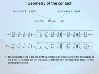
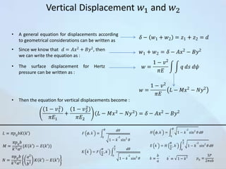
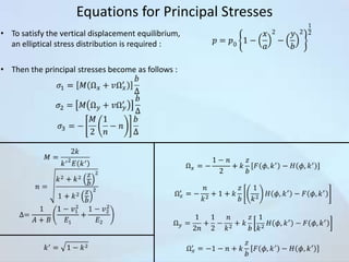
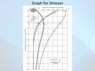
Downloaded 184 times


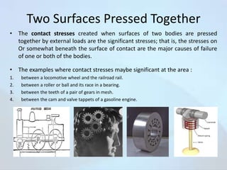
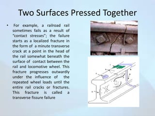
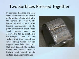
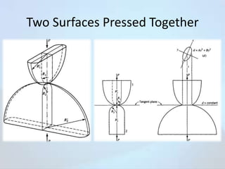
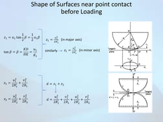
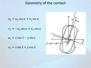
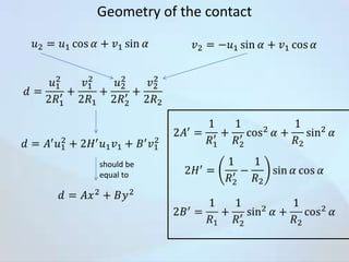


The document discusses contact stresses that occur between two surfaces pressed together, such as between a locomotive wheel and rail. It provides examples where contact stresses are significant, like in bearings and gears. When surfaces are pressed together, high stresses develop just below the surface at the point of contact. These stresses can cause failures like cracking or pitting. The document presents equations to calculate the principal stresses that develop from an elliptical stress distribution between the pressed surfaces. Factors like the curvature of the surfaces and angle of contact are considered. Charts are also included showing stress distribution parameters for different angles of contact.


