Downloaded 1,220 times

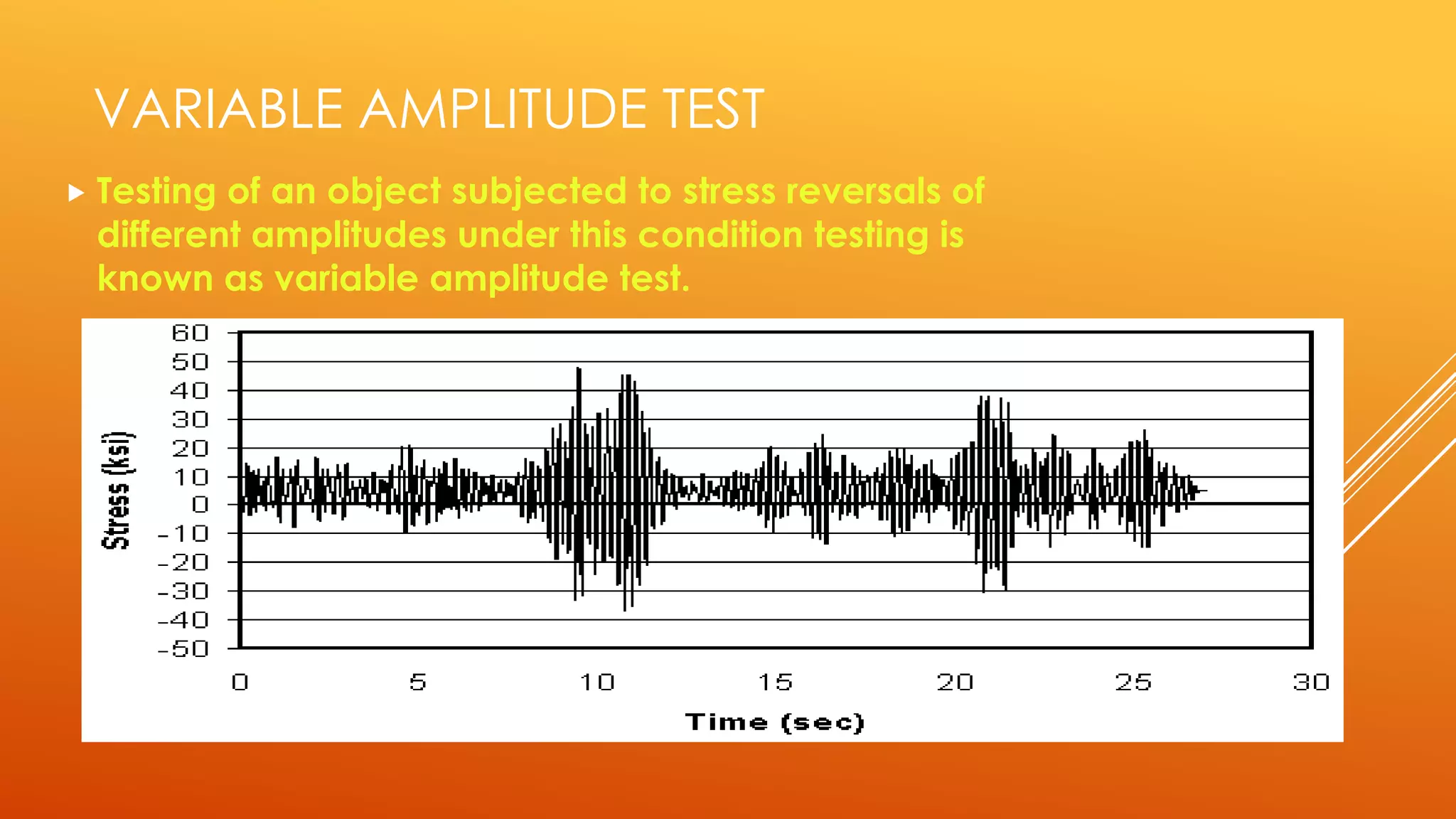
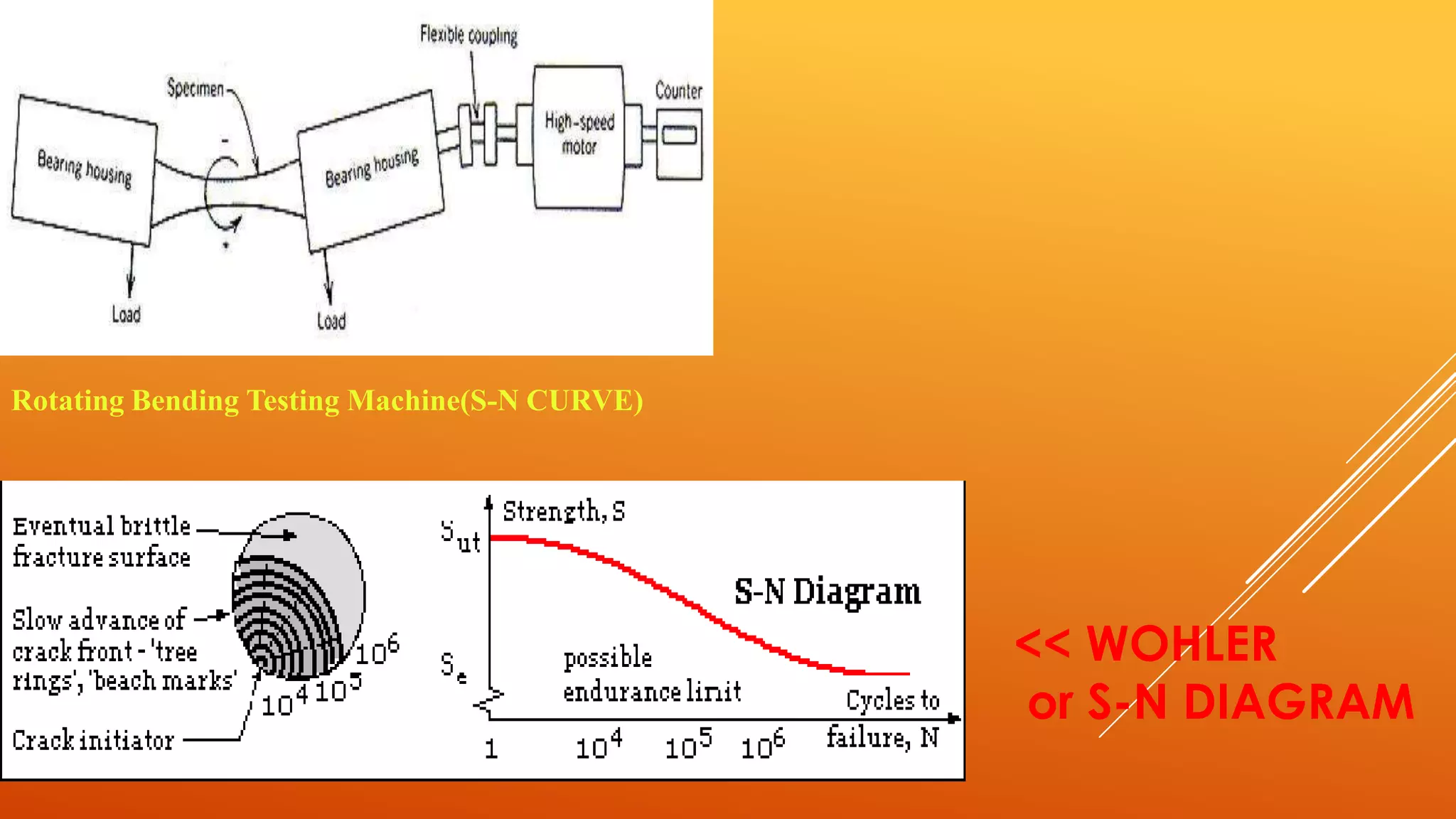


Fatigue testing involves subjecting materials to repetitive loads or stresses to determine their fatigue life. There are two main types of fatigue testing: constant amplitude testing, where the stress level remains constant for each cycle, and variable amplitude testing, where the stress level varies each cycle. Fatigue testing can be done on standardized test specimens or actual components. Common machines used include rotating beam machines, where a stationary load bends a rotating specimen, creating repeated stresses. The results of fatigue testing are often displayed using an S-N curve to show the relationship between stress levels and the number of cycles before failure.


