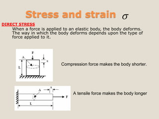
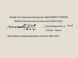
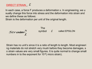
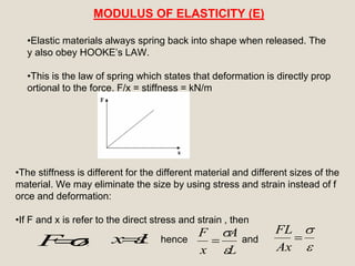
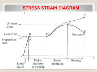
1. Active Learning Assignment
(Mechanics of Solid )(2131903)
Topic:- Stress Strain and Basic concept
Mechanical Engineering (3 C3)
Prepared By:
Chandresh Suthar (140120119229)
Sonani Mananv (140120119229)
Govind Tade (140120119230)
Shah Shrey (140120119211)
Guided by:
Prof. Hiren Raghu
2. Flow of content
Basic concept of stress & strain
Direct Strain
Module of elasticity
Stress strain diagram
Shear stress
Module of rigidity
3. Stress and strain
DIRECT STRESS
When a force is applied to an elastic body, the body deforms.
The way in which the body deforms depends upon the type of
force applied to it.
Compression force makes the body shorter.
A tensile force makes the body longer
4. A
F
Area
Force
Stress
2
/mN
Tensile and compressive forces are called DIRECT FORCES
Stress is the force per unit area upon which it acts.
….. Unit is Pascal (Pa) or
Note: Most of engineering fields used kPa, MPa, GPa.
( Simbol – Sigma)
5.
L
x
Strain
DIRECT STRAIN ,
In each case, a force F produces a deformation x. In engineering, we u
sually change this force into stress and the deformation into strain and
we define these as follows:
Strain is the deformation per unit of the original length.
The
symbol
Strain has no unit’s since it is a ratio of length to length. Most engineeri
ng materials do not stretch very mush before they become damages, s
o strain values are very small figures. It is quite normal to change small
numbers in to the exponent for 10-6( micro strain).
called EPSILON
6. MODULUS OF ELASTICITY (E)
•Elastic materials always spring back into shape when released. The
y also obey HOOKE’s LAW.
•This is the law of spring which states that deformation is directly prop
ortional to the force. F/x = stiffness = kN/m
•The stiffness is different for the different material and different sizes of the
material. We may eliminate the size by using stress and strain instead of f
orce and deformation:
•If F and x is refer to the direct stress and strain , then
AF Lx
L
A
x
F
Ax
FL
hence and
7. E
Ax
FL
•The stiffness is now in terms of stress and strain only and this consta
nt is called the MODULUS of ELASTICITY (E)
• A graph of stress against strain will be straight line with gra
dient of E. The units of E are the same as the unit of stress.
ULTIMATE TENSILE STRESS
•If a material is stretched until it breaks, the tensile stress has reac
hed the absolute limit and this stress level is called the ultimate ten
sile stress.
9. STRESS STRAIN DIAGRAM
Elastic behaviour
The curve is straight line trough out most of the region
Stress is proportional with strain
Material to be linearly elastic
Proportional limit
The upper limit to linear line
The material still respond elastically
The curve tend to bend and flatten out
Elastic limit
Upon reaching this point, if load is remove, the sp
ecimen still return to original shape
10. STRESS STRAIN DIAGRAM
Yielding
A Slight increase in stress above the elastic limit will r
esult in breakdown of the material and cause it to defor
m permanently.
This behaviour is called yielding
The stress that cause = YIELD STRESS@YIELD POI
NT
Plastic deformation
Once yield point is reached, the specimen will elongat
e (Strain) without any increase in load
Material in this state = perfectly plastic
11. STRESS STRAIN DIAGRAM
STRAIN HARDENING
When yielding has ended, further load applied, resulting in a curve tha
t rises continuously
Become flat when reached ULTIMATE STRESS
The rise in the curve = STRAIN HARDENING
While specimen is elongating, its cross sectional will decrease
The decrease is fairly uniform
NECKING
At the ultimate stress, the cross sectional area begins its localised regi
on of specimen
it is caused by slip planes formed within material
Actual strain produced by shear strain
As a result, “neck” tend to form
Smaller area can only carry lesser load, hence curve donward
Specimen break at FRACTURE STRESS
12. SHEAR STRESS
•Shear force is a force applied sideways on the material (transvers
ely loaded).
When a pair of shears cut a material
When a material is punched
When a beam has a transverse load
13. Shear stress is the force per unit area carrying the
load. This means the cross sectional area of the ma
terial being cut, the beam and pin.
A
F
and symbol is called Tau•Shear stress,
The sign convention for shear force and stress is base
d on how it shears the materials as shown below.
14.
L
x
L
x
SHEAR STRAIN
The force causes the material to deform as shown. The shear strain i
s defined as the ratio of the distance deformed to the height
. Since this is a very small angle , we can say that :
( symbol called
Gamma)
Shear strain
15. •If we conduct an experiment and measure x for various values of F,
we would find that if the material is elastic, it behave like spring and
so long as we do not damage the material by using too big force, th
e graph of F and x is straight line as shown.
MODULUS OF RIGIDITY (G)
The gradient of the graph is constant so tcons
x
F
tan
and this is the spring stiffness of the block in N/m.
•If we divide F by area A and x by the height L, the relationship is st
ill a constant and we get
17. ULTIMATE SHEAR STRESS
If a material is sheared beyond a certain limit and it becomes pe
rmanently distorted and does not spring all the way back to its ori
ginal shape, the elastic limit has been exceeded.
If the material stressed to the limit so that it parts into two, the ul
timate limit has been reached.
The ultimate shear stress has symbol and this value is used
to calculate the force needed by shears and punches.
18. DOUBLE SHEAR
Consider a pin joint with a support on both ends as shown. This
is called CLEVIS and CLEVIS PIN
By balance of force, the force in the two supports is F/2 each
The area sheared is twice the cross section of the pin
So it takes twice as much force to break the pin as for a case of
single shear
Double shear arrangements doubles the maximum force allowe
d in the pin
19. LOAD AND STRESS LIMIT
DESIGN CONSIDERATION
Will help engineers with their important task in Designing structur
al/machine that is SAFE and ECONOMICALLY perform for a spec
ified function
DETERMINATION OF ULTIMATE STRENGTH
An important element to be considered by a designer is how the
material that has been selected will behave under a load
This is determined by performing specific test (e.g. Tensile test)
ULTIMATE FORCE (PU)= The largest force that may be applied t
o the specimen is reached, and the specimen either breaks or beg
ins to carry less load
ULTIMATE NORMAL STRESS
(U) = ULTIMATE FORCE(PU) /AREA
20. ALLOWABLE LOAD / ALLOWABLE STRESS
Max load that a structural member/machine component will be allowed t
o carry under normal conditions of utilisation is considerably smaller than
the ultimate load
This smaller load = Allowable load / Working load / Design load
Only a fraction of ultimate load capacity of the member is utilised when
allowable load is applied
The remaining portion of the load-carrying capacity of the member is ke
pt in reserve to assure its safe performance
The ratio of the ultimate load/allowable load is used to define FACTOR
OF SAFETY
FACTOR OF SAFETY = ULTIMATE LOAD/ALLOWABLE LOAD
@
FACTOR OF SAFETY = ULTIMATE STRESS/ALLOWABLE STRESS
21. SELECTION OF F.S.
1. Variations that may occur in the properties of the member under consi
derations
2. The number of loading that may be expected during the life of the stru
ctural/machine
3. The type of loading that are planned for in the design, or that may occ
ur in the future
4. The type of failure that may occur
5. Uncertainty due to the methods of analysis
6. Deterioration that may occur in the future because of poor maintenan
ce / because of unpreventable natural causes
7. The importance of a given member to the integrity of the whole struct
ure
22. AXIAL FORCE & DEFLECTION OF BODY
Deformations of members under axial loading
If the resulting axial stress does not exceed the proportional limit of
the material, Hooke’s Law may be applied
Then deformation (x / ) can be written as
AE
FL
E