Downloaded 874 times


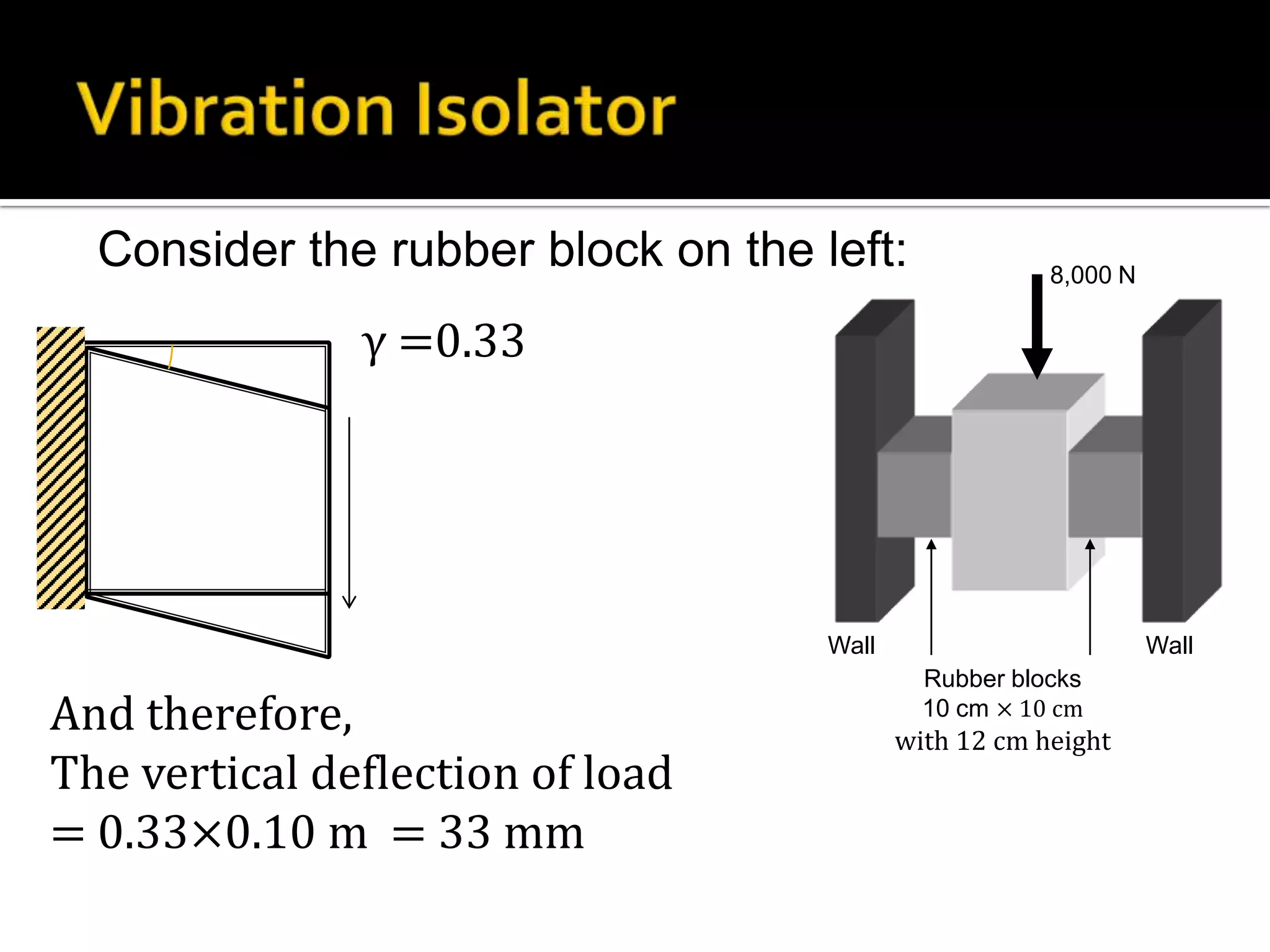
![Tension in the cable at the lowest point is;
To = 2.96×10⁸ N
Max tension = 3.23×10⁸ N
Each cable consists of 27,572
strands of 4.88-mm diameter
wires bundled parallel.
Cross-sectional area of the cable =
27,572×[π×0.004882/4] = 0.516 m2
So stress = 625.5 MPa](https://image.slidesharecdn.com/strengthofmaterialbyaditya-131214222324-phpapp01/75/Strength-of-Materials-99-2048.jpg)


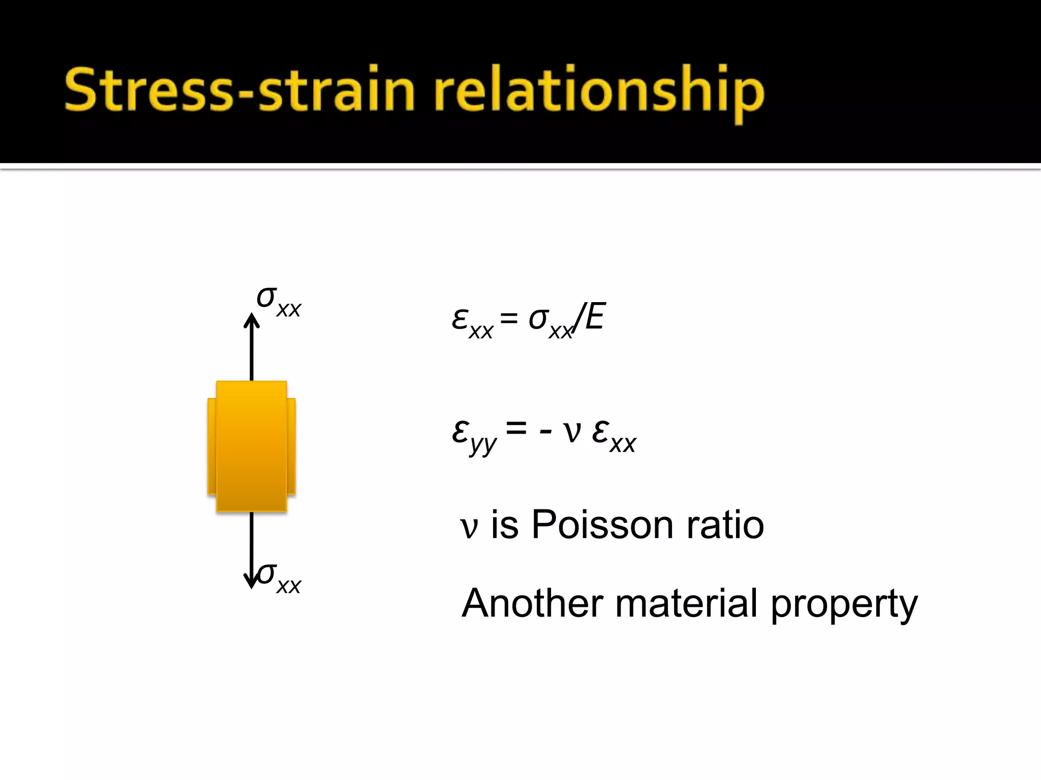
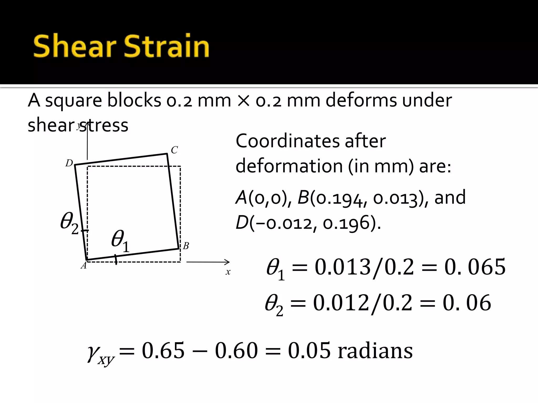
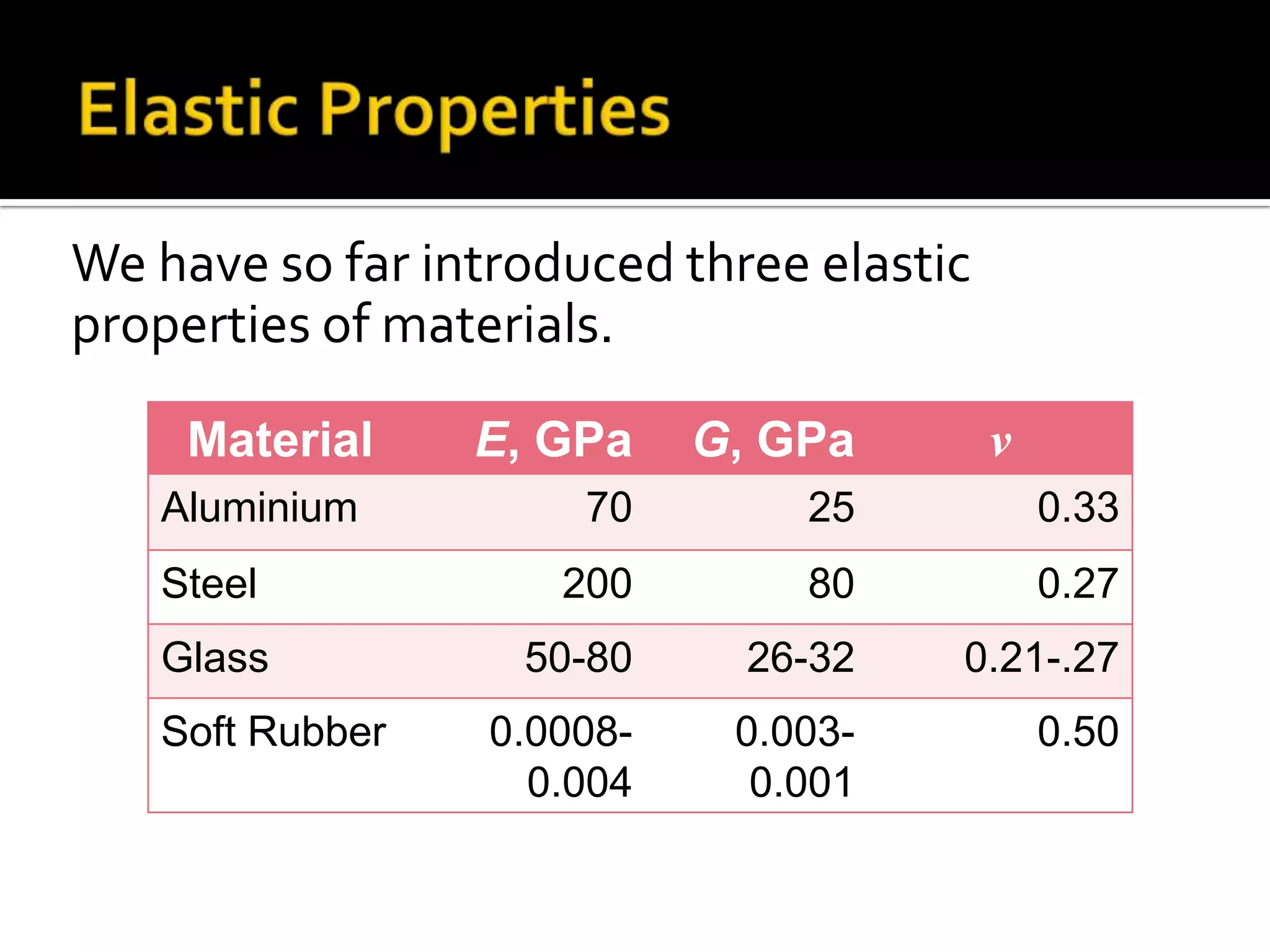
![Shear stresses do not cause any normal strain
Therefore,
εxx = ζxx/E – νζyy/E - ν ζzz/E
= [ζxx – ν(ζyy + σzz)]/E
Similarly for εyy and εzz](https://image.slidesharecdn.com/strengthofmaterialbyaditya-131214222324-phpapp01/75/Strength-of-Materials-129-2048.jpg)
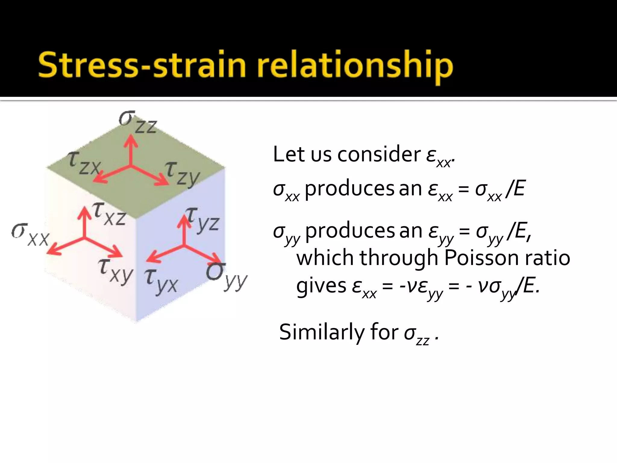
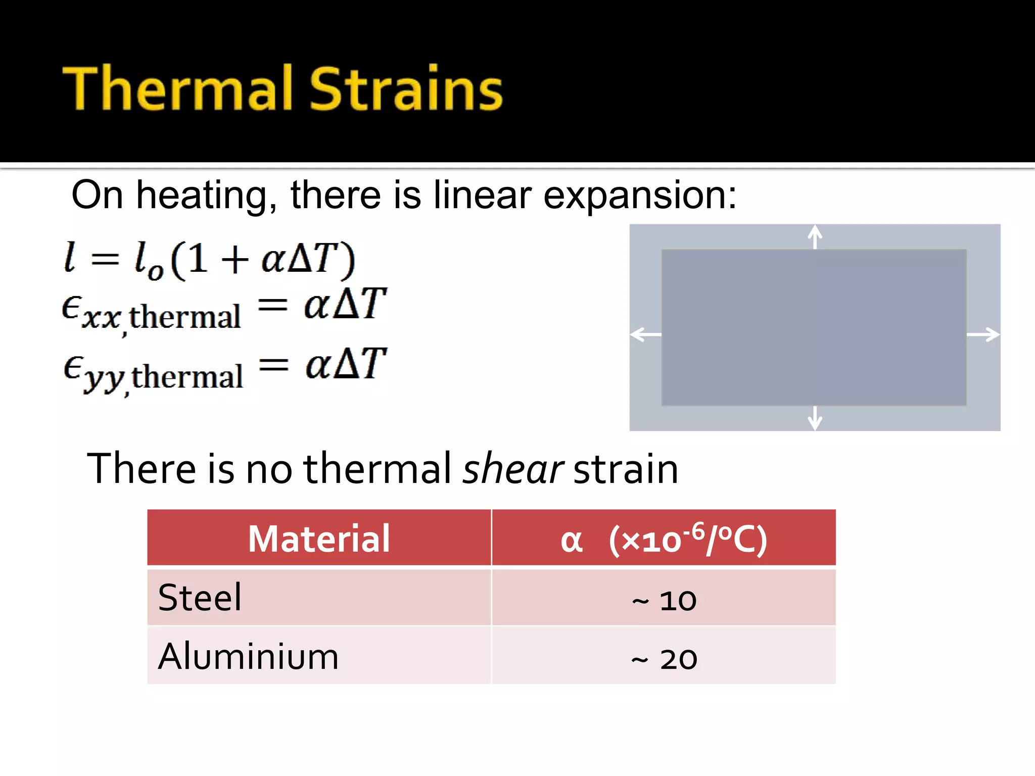
![F
ζyy = −F/A, ζzz = 0
What is ζxx and εyy
y
x
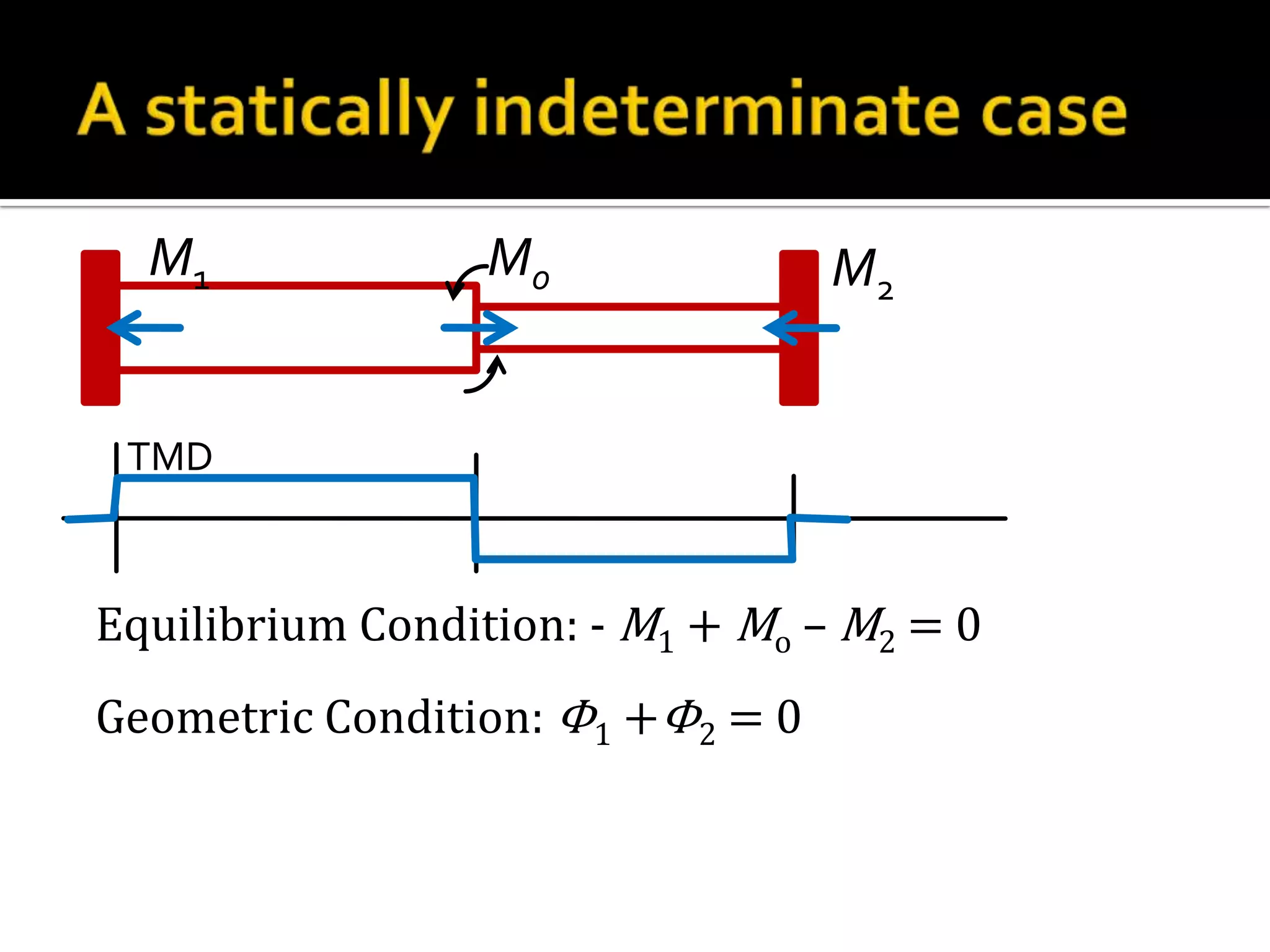
Geometric compatibility:
εxx = 0
εxx = [ζxx – ν(ζyy + ζzz)]/E
0 = [ζxx – ν(ζyy + 0)]/E,
→ ζxx =νζyy = − ν F/A
εyy = [ζyy – ν(ζxx + ζzz)]/E = [−F/A + ν F/A]/E = −(1− ν)F/AE](https://image.slidesharecdn.com/strengthofmaterialbyaditya-131214222324-phpapp01/75/Strength-of-Materials-130-2048.jpg)
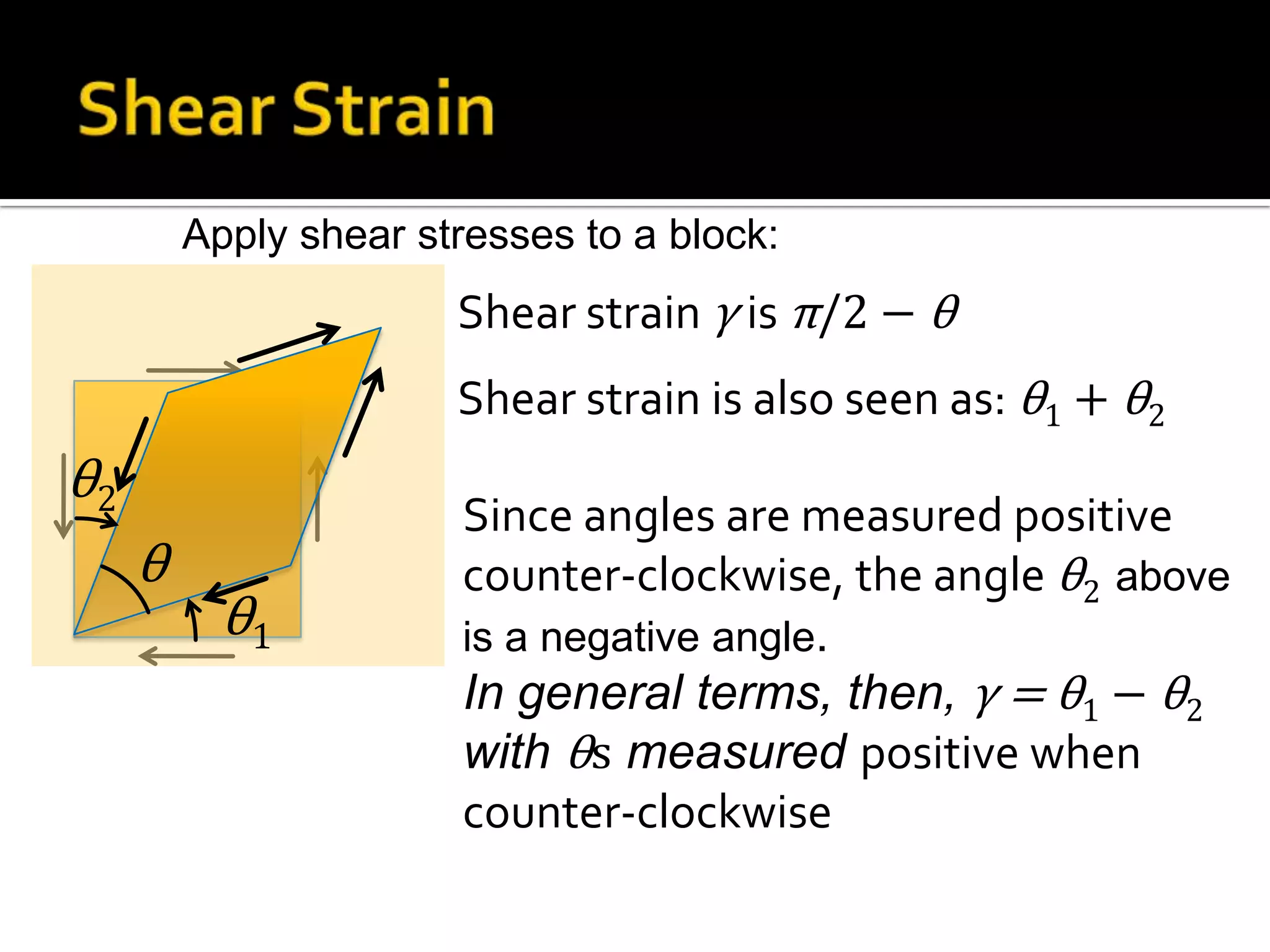
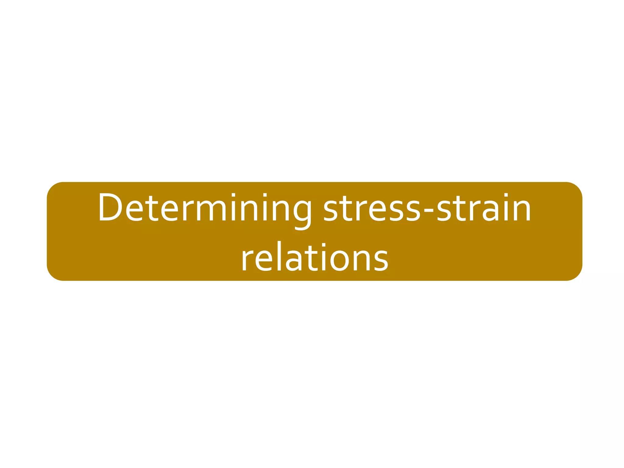
![σyy
Steel: εx = 0.6×10⁻⁴
εy = 0.3×10⁻⁴
Find σxx and σyy :
Plug in:
εxx = [σxx – ν(σyy + σzz)]/E
εyy = [σyy – ν(σzz + σxx)]/E
E = 200 GPa, ν = 0.3
σxx](https://image.slidesharecdn.com/strengthofmaterialbyaditya-131214222324-phpapp01/75/Strength-of-Materials-131-2048.jpg)

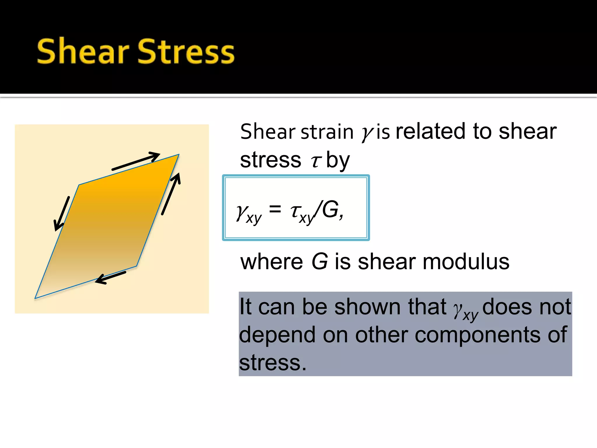

![Putting Hooke law, Poisson effect and thermal
strains all together,
εxx = [σxx – ν(σyy + σzz)]/E + αΔT
εyy = [σyy – ν(σzz + σxx)]/E+ αΔT
εzz = [σzz – ν(σxx + σyy)]/E+ αΔT
γxy = τxy/G, γyz = τyz/G, and γzx = τzx/G](https://image.slidesharecdn.com/strengthofmaterialbyaditya-131214222324-phpapp01/75/Strength-of-Materials-142-2048.jpg)
![Aluminium rod, rigid supports.
Temperature raised by ΔT.
What are the stresses?
εxx = 0 = [σxx/E + αΔT]
σxx = −αEΔT
x](https://image.slidesharecdn.com/strengthofmaterialbyaditya-131214222324-phpapp01/75/Strength-of-Materials-143-2048.jpg)
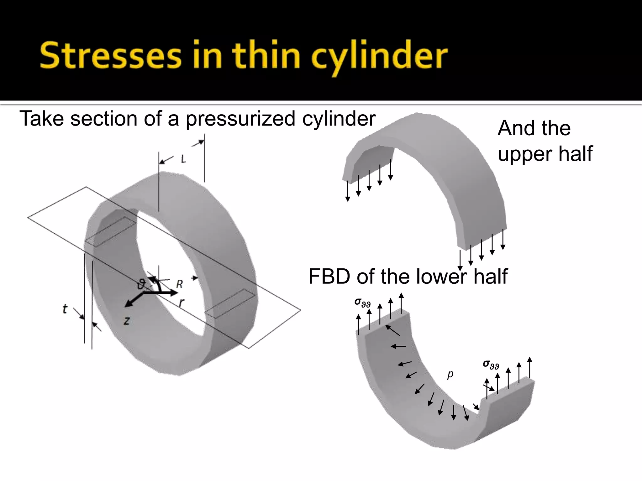
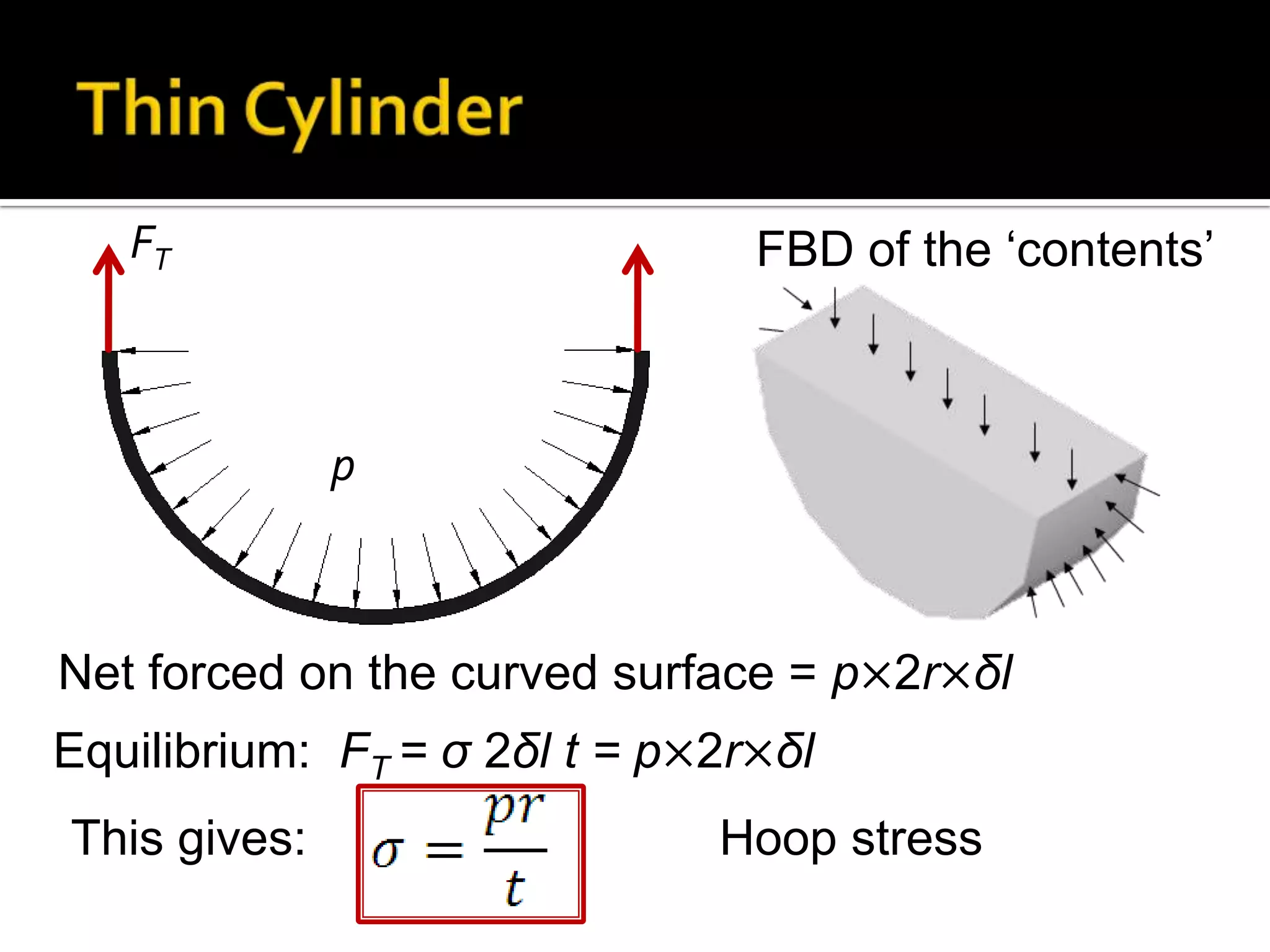
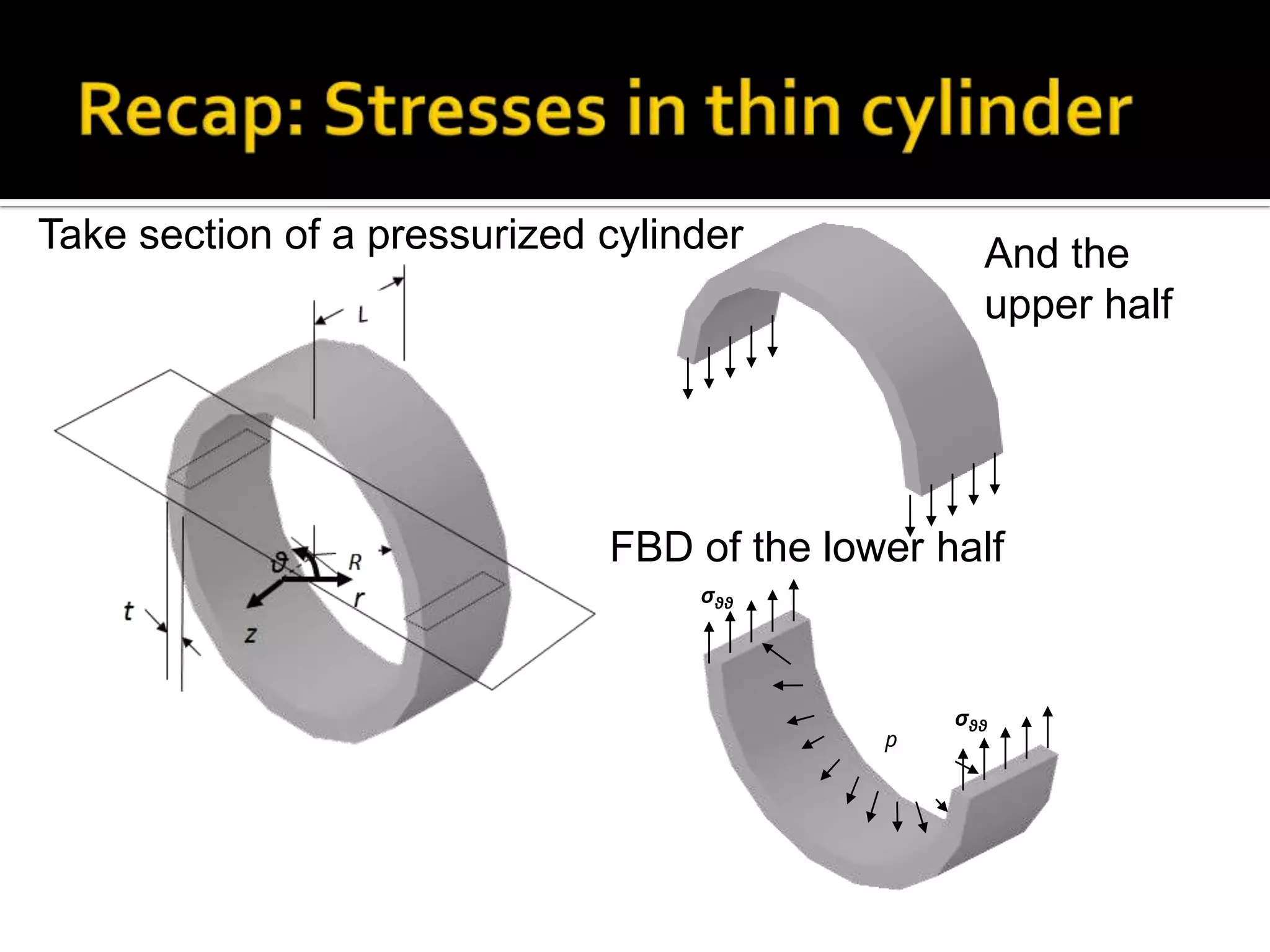
![Tank is flush when empty.
Find end forces when pressure is p
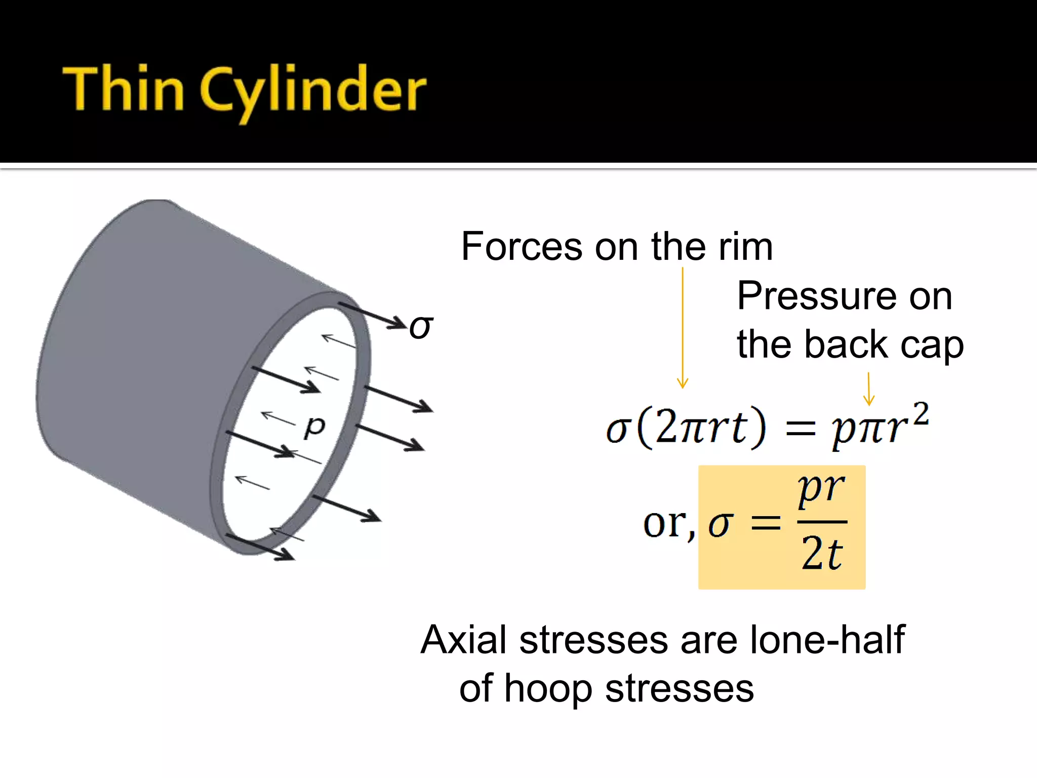
Due to p: σzz = pr/ 2t, σθθ = pr/ t
z
If end forces F, axial stress due to it
is F/2πrt
εzz = [(pr/ 2t − F/2πrt) −νpr/t ]/E
Equate it to 0 and determine F
p](https://image.slidesharecdn.com/strengthofmaterialbyaditya-131214222324-phpapp01/75/Strength-of-Materials-144-2048.jpg)


1. The document discusses structures, loads, stresses, strains and material properties related to mechanics of materials. 2. It defines key terms like stress, strain, elastic modulus and explains stress-strain relationships. Common stress types like tensile, compressive, shear and their effects are described. 3. Examples of different structures like cylinders, spheres, arches, towers and bridges are provided to illustrate stress distributions and effects of loads. Material properties of common materials are also listed.


