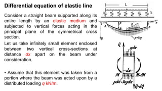
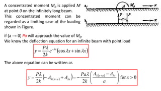
Lecture 2
Elastic Analysis of Pile Foundation
(Beams on Elastic Foundation)
Differential equation of elastic line
Consider a straight beam supported along its
entire length by an elastic medium and
subjected to vertical forces acting in the
principal plane of the symmetrical cross
section.
Let us take infinitely small element enclosed
between two vertical cross-sections at
distance dx apart on the beam under
consideration.
• Assume that this element was taken from a
portion where the beam was acted upon by a
distributed loading q kN/m.
The forces exerted on such an element are:
By putting Q = dM/dx,
Using differential equation of a beam in bending, 𝐸𝐼
𝑑2𝑦
𝑑𝑥2 = −𝑀, and
differentiating it twice,
This is the differential equation for the deflection curve of a beam supported on an
elastic foundation.
 
q
ky
dx
dQ
dx
q
dx
y
k
dQ
Q
Q







 0
q
ky
dx
M
d
dx
dQ


 2
2
 
1
......
..........
..........
..........
..........
4
4
2
2
4
4
q
ky
dx
y
d
EI
dx
M
d
dx
y
d
EI






















Along the unloaded parts of the beam, q = 0, and the equation above will take
the form
It will be sufficient to consider only the general solution of (2),from which
solutions will be obtained by adding to it a particular integral corresponding to q
in (1).
Substituting y = emx in (2), we obtain the characteristic equation:
which has roots:
 
2
..........
..........
..........
..........
4
4
ky
dx
y
d
EI 









EI
k
m 

4
   
   
i
i
EI
k
m
m
i
i
EI
k
m
m














1
1
4
1
1
4
4
4
2
4
3
1


The general solution of (2) takes the form
Where
Using eiλx = cosλx + i sinλx
e-iλx = cosλx - i sinλx
Introducing the new constants C1, C2, C3 and C4, where
We can write
 
3
...
..........
..........
..........
4
3
2
1
4
3
2
1
x
m
x
m
x
m
x
m
e
A
e
A
e
A
e
A
y 



4
4EI
k


   
    4
3
2
3
3
2
2
4
1
1
4
1
;
;
C
A
A
i
C
A
A
C
A
A
i
C
A
A








     
4
.........
..........
sin
cos
sin
cos 4
3
2
1 x
C
x
C
e
x
C
x
C
e
y x
x



 




 
The general solution for the deflection line of a straight prismatic bar
supported on an elastic foundation and subjected to transverse bending
forces, but with no surcharge loading (q).
λ is called the characteristic of the system and the inverse is called
characteristic length.
By differentiation of the above equation, we get
   
x
C
x
C
e
x
C
x
C
e
y x
x



 

sin
cos
sin
cos 4
3
2
1 


 
   
 
   
 
x
x
C
x
x
C
e
x
x
C
x
x
C
e
dx
dy
x
x











sin
cos
sin
cos
sin
cos
sin
cos
1
4
3
2
1









By differentiation, we get
We know that
   
x
C
x
C
e
x
C
x
C
e
y x
x



 

sin
cos
sin
cos 4
3
2
1 


 
   
 
   
 
   
   
 
   
 
x
x
C
x
x
C
e
x
x
C
x
x
C
e
dx
y
d
x
C
x
C
e
x
C
x
C
e
dx
y
d
x
x
C
x
x
C
e
x
x
C
x
x
C
e
dx
dy
x
x
x
x
x
x





























sin
cos
sin
cos
sin
cos
sin
cos
2
1
cos
sin
cos
sin
2
1
sin
cos
sin
cos
sin
cos
sin
cos
1
4
3
2
1
3
3
3
4
3
2
1
2
2
2
4
3
2
1

























Q
dx
y
d
EI
M
dx
y
d
EI
dx
dy




 3
3
2
2
,
,

Infinite Beam on Elastic Foundation
The general solution for the deflection curve of a beam subjected to transverse
loading can be written as:
In this problem, it is reasonable to assume that in an infinite distance from the
application of the load the deflection of the beam must approach zero, that is, if
x→∞, then y→0. Under this condition C1 = C2=0.
Consider a beam of unlimited length in
both directions (an infinite beam)
subjected to a single concentrated force
P at point O.
   
x
C
x
C
e
x
C
x
C
e
y x
x



 

sin
cos
sin
cos 4
3
2
1 


 
 
x
C
x
C
e
y x



sin
cos 4
3 
 
From the condition of symmetry, we know that
that is, — (C3 — C4) = 0, from which we find C3 = C4 = C.
This last constant of the equation can be obtained from the consideration
that the sum of the reaction forces will keep equilibrium with the load P,
0
0








x
dx
dy
 
x
x
Ce
y x



sin
cos 
 
 
k
P
C
P
kC
P
dx
x
x
e
kC
P
dx
y
k x
2
2
sin
cos
2
2
0
0












 




Substituting the value of C, we have
which gives the deflection curve for the right side (x0) of the beam.
• This deflection curve is a wavy line with decreasing amplitude.
• The deflection under the load is y0 = Pλ/2k.
• The zero points of the line are where cosλx + sinλx = 0, that is, at the
consecutive values of
3
4
𝜋;
7
4
𝜋;
11
4
𝜋 etc.
 
x
x
e
k
P
y x


 
sin
cos
2

 
Taking the successive derivatives of y w.r.t. x, we obtain the expressions for θ,
M, and Q on the right side of the beam as
 
 
x
e
P
Q
dx
y
d
EI
x
x
e
P
M
dx
y
d
EI
x
e
k
P
dx
dy
x
x
e
k
P
y
x
x
x
x














cos
2
sin
cos
4
sin
sin
cos
2
3
3
2
2
2

















 
 
x
x
x
x
x
x
x
x
D
P
x
e
P
Q
dx
y
d
EI
C
P
x
x
e
P
M
dx
y
d
EI
B
k
P
x
e
k
P
dx
dy
A
k
P
x
x
e
k
P
y





















2
cos
2
4
sin
cos
4
sin
2
sin
cos
2
3
3
2
2
2
2























On the left side the y and M curves
will keep the same signs ( yx = y-x and
Mx = M-x), but θ and Q will change
their signs (θx = - θ-x and Qx = - Q -x),
 
 
x
e
D
x
x
e
C
x
e
B
x
x
e
A
x
x
x
x
x
x
x
x














cos
sin
cos
sin
sin
cos










if (a → 0) Pa will approach the value of M0.
We know the deflection equation for an infinite beam with point load
The above equation can be written as
A concentrated moment M0 is applied M
at point 0 on the infinitely long beam.
This concentrated moment can be
regarded as a limiting case of the loading
shown in Figure.
 
x
x
e
k
P
y x


 
sin
cos
2

 
 
   
0
for
2
2








 




 
 x
a
A
A
k
Pa
A
A
k
P
y x
a
x
x
a
x






Since
At the same time
Deflection line due to the M0 clockwise
moment as
 
x
x
a
x
a
x
B
A
dx
d
a
A
A





2
0










 


  0
0 M
Pa a 

x
x
x
x
A
M
Q
dx
y
d
EI
D
M
M
dx
y
d
EI
C
k
M
dx
dy
B
k
M
y








2
2
0
3
3
0
2
2
3
0
2
0











Beams on Elastic Foundation2.pdf

  • 1.
    Lecture 2 Elastic Analysisof Pile Foundation (Beams on Elastic Foundation)
  • 2.
    Differential equation ofelastic line Consider a straight beam supported along its entire length by an elastic medium and subjected to vertical forces acting in the principal plane of the symmetrical cross section. Let us take infinitely small element enclosed between two vertical cross-sections at distance dx apart on the beam under consideration. • Assume that this element was taken from a portion where the beam was acted upon by a distributed loading q kN/m.
  • 3.
    The forces exertedon such an element are: By putting Q = dM/dx, Using differential equation of a beam in bending, 𝐸𝐼 𝑑2𝑦 𝑑𝑥2 = −𝑀, and differentiating it twice, This is the differential equation for the deflection curve of a beam supported on an elastic foundation.   q ky dx dQ dx q dx y k dQ Q Q         0 q ky dx M d dx dQ    2 2   1 ...... .......... .......... .......... .......... 4 4 2 2 4 4 q ky dx y d EI dx M d dx y d EI                      
  • 4.
    Along the unloadedparts of the beam, q = 0, and the equation above will take the form It will be sufficient to consider only the general solution of (2),from which solutions will be obtained by adding to it a particular integral corresponding to q in (1). Substituting y = emx in (2), we obtain the characteristic equation: which has roots:   2 .......... .......... .......... .......... 4 4 ky dx y d EI           EI k m   4         i i EI k m m i i EI k m m               1 1 4 1 1 4 4 4 2 4 3 1  
  • 5.
    The general solutionof (2) takes the form Where Using eiλx = cosλx + i sinλx e-iλx = cosλx - i sinλx Introducing the new constants C1, C2, C3 and C4, where We can write   3 ... .......... .......... .......... 4 3 2 1 4 3 2 1 x m x m x m x m e A e A e A e A y     4 4EI k           4 3 2 3 3 2 2 4 1 1 4 1 ; ; C A A i C A A C A A i C A A               4 ......... .......... sin cos sin cos 4 3 2 1 x C x C e x C x C e y x x           
  • 6.
    The general solutionfor the deflection line of a straight prismatic bar supported on an elastic foundation and subjected to transverse bending forces, but with no surcharge loading (q). λ is called the characteristic of the system and the inverse is called characteristic length. By differentiation of the above equation, we get     x C x C e x C x C e y x x       sin cos sin cos 4 3 2 1                  x x C x x C e x x C x x C e dx dy x x            sin cos sin cos sin cos sin cos 1 4 3 2 1         
  • 7.
    By differentiation, weget We know that     x C x C e x C x C e y x x       sin cos sin cos 4 3 2 1                                  x x C x x C e x x C x x C e dx y d x C x C e x C x C e dx y d x x C x x C e x x C x x C e dx dy x x x x x x                              sin cos sin cos sin cos sin cos 2 1 cos sin cos sin 2 1 sin cos sin cos sin cos sin cos 1 4 3 2 1 3 3 3 4 3 2 1 2 2 2 4 3 2 1                          Q dx y d EI M dx y d EI dx dy      3 3 2 2 , , 
  • 8.
    Infinite Beam onElastic Foundation
  • 9.
    The general solutionfor the deflection curve of a beam subjected to transverse loading can be written as: In this problem, it is reasonable to assume that in an infinite distance from the application of the load the deflection of the beam must approach zero, that is, if x→∞, then y→0. Under this condition C1 = C2=0. Consider a beam of unlimited length in both directions (an infinite beam) subjected to a single concentrated force P at point O.     x C x C e x C x C e y x x       sin cos sin cos 4 3 2 1        x C x C e y x    sin cos 4 3   
  • 10.
    From the conditionof symmetry, we know that that is, — (C3 — C4) = 0, from which we find C3 = C4 = C. This last constant of the equation can be obtained from the consideration that the sum of the reaction forces will keep equilibrium with the load P, 0 0         x dx dy   x x Ce y x    sin cos      k P C P kC P dx x x e kC P dx y k x 2 2 sin cos 2 2 0 0                  
  • 11.
    Substituting the valueof C, we have which gives the deflection curve for the right side (x0) of the beam. • This deflection curve is a wavy line with decreasing amplitude. • The deflection under the load is y0 = Pλ/2k. • The zero points of the line are where cosλx + sinλx = 0, that is, at the consecutive values of 3 4 𝜋; 7 4 𝜋; 11 4 𝜋 etc.   x x e k P y x     sin cos 2   
  • 12.
    Taking the successivederivatives of y w.r.t. x, we obtain the expressions for θ, M, and Q on the right side of the beam as     x e P Q dx y d EI x x e P M dx y d EI x e k P dx dy x x e k P y x x x x               cos 2 sin cos 4 sin sin cos 2 3 3 2 2 2                 
  • 13.
  • 14.
  • 15.
    if (a →0) Pa will approach the value of M0. We know the deflection equation for an infinite beam with point load The above equation can be written as A concentrated moment M0 is applied M at point 0 on the infinitely long beam. This concentrated moment can be regarded as a limiting case of the loading shown in Figure.   x x e k P y x     sin cos 2          0 for 2 2                  x a A A k Pa A A k P y x a x x a x      
  • 16.
    Since At the sametime Deflection line due to the M0 clockwise moment as   x x a x a x B A dx d a A A      2 0                 0 0 M Pa a   x x x x A M Q dx y d EI D M M dx y d EI C k M dx dy B k M y         2 2 0 3 3 0 2 2 3 0 2 0          