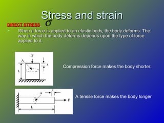
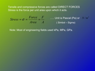
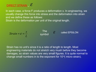
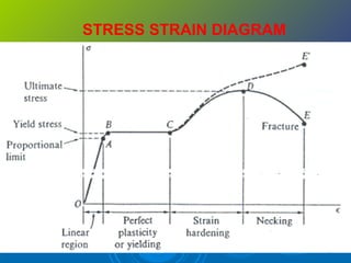
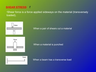
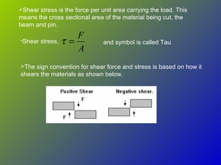
Stress and strainStress and strain
DIRECT STRESSDIRECT STRESS
 When a force is applied to an elastic body, the body deforms. TheWhen a force is applied to an elastic body, the body deforms. The
way in which the body deforms depends upon the type of forceway in which the body deforms depends upon the type of force
applied to it.applied to it.
Compression force makes the body shorter.
A tensile force makes the body longer
σ
A
F
Area
Force
Stress === σ
2
/ mN
Tensile and compressive forces are called DIRECT FORCES
Stress is the force per unit area upon which it acts.
….. Unit is Pascal (Pa) or
Note: Most of engineering fields used kPa, MPa, GPa.
( Simbol – Sigma)
Îľ
L
x
Strain == Îľ Îľ
DIRECT STRAIN ,
In each case, a force F produces a deformation x. In engineering, we
usually change this force into stress and the deformation into strain
and we define these as follows:
Strain is the deformation per unit of the original length.
The
symbol
Strain has no unit’s since it is a ratio of length to length. Most
engineering materials do not stretch very mush before they become
damages, so strain values are very small figures. It is quite normal to
change small numbers in to the exponent for 10-6
( micro strain).
called EPSILON
STRESS STRAIN DIAGRAM
Elastic behaviour
•The curve is straight line trough out most of the region
•Stress is proportional with strain
•Material to be linearly elastic
•Proportional limit
•The upper limit to linear line
•The material still respond elastically
•The curve tend to bend and flatten out
•Elastic limit
•Upon reaching this point, if load is remove, the
specimen still return to original shape
STRESS STRAIN DIAGRAM
Yielding
• A Slight increase in stress above the elastic limit will
result in breakdown of the material and cause it to
deform permanently.
•This behaviour is called yielding
•The stress that cause = YIELD STRESS@YIELD
POINT
•Plastic deformation
•Once yield point is reached, the specimen will
elongate (Strain) without any increase in load
•Material in this state = perfectly plastic
STRESS STRAIN DIAGRAM
 STRAIN HARDENING

When yielding has ended, further load applied, resulting in a curve
that rises continuously

Become flat when reached ULTIMATE STRESS

The rise in the curve = STRAIN HARDENING

While specimen is elongating, its cross sectional will decrease

The decrease is fairly uniform
 NECKING

At the ultimate stress, the cross sectional area begins its localised
region of specimen

it is caused by slip planes formed within material

Actual strain produced by shear strain

As a result, “neck” tend to form

Smaller area can only carry lesser load, hence curve donward

Specimen break at FRACTURE STRESS
SHEAR STRESS τ
•Shear force is a force applied sideways on the material (transversely
loaded).
When a pair of shears cut a material
When a material is punched
When a beam has a transverse load
Shear stress is the force per unit area carrying the load. This
means the cross sectional area of the material being cut, the
beam and pin.
A
F
=τ and symbol is called Tau•Shear stress,
The sign convention for shear force and stress is based on how it
shears the materials as shown below.
ULTIMATE SHEAR STRESS
•If a material is sheared beyond a certain limit and it becomes
permanently distorted and does not spring all the way back to its
original shape, the elastic limit has been exceeded.
•If the material stressed to the limit so that it parts into two, the
ultimate limit has been reached.
•The ultimate shear stress has symbol and this value is used
to calculate the force needed by shears and punches.
τ
ULTIMATE TENSILE STRESS
•If a material is stretched until it breaks, the tensile stress has
reached the absolute limit and this stress level is called the
ultimate tensile stress.
Stress strain sm (1) (1)

Stress strain sm (1) (1)

  • 1.
    Stress and strainStressand strain DIRECT STRESSDIRECT STRESS  When a force is applied to an elastic body, the body deforms. TheWhen a force is applied to an elastic body, the body deforms. The way in which the body deforms depends upon the type of forceway in which the body deforms depends upon the type of force applied to it.applied to it. Compression force makes the body shorter. A tensile force makes the body longer σ
  • 2.
    A F Area Force Stress === σ 2 /mN Tensile and compressive forces are called DIRECT FORCES Stress is the force per unit area upon which it acts. ….. Unit is Pascal (Pa) or Note: Most of engineering fields used kPa, MPa, GPa. ( Simbol – Sigma)
  • 3.
    ε L x Strain == εε DIRECT STRAIN , In each case, a force F produces a deformation x. In engineering, we usually change this force into stress and the deformation into strain and we define these as follows: Strain is the deformation per unit of the original length. The symbol Strain has no unit’s since it is a ratio of length to length. Most engineering materials do not stretch very mush before they become damages, so strain values are very small figures. It is quite normal to change small numbers in to the exponent for 10-6 ( micro strain). called EPSILON
  • 4.
  • 5.
    STRESS STRAIN DIAGRAM Elasticbehaviour •The curve is straight line trough out most of the region •Stress is proportional with strain •Material to be linearly elastic •Proportional limit •The upper limit to linear line •The material still respond elastically •The curve tend to bend and flatten out •Elastic limit •Upon reaching this point, if load is remove, the specimen still return to original shape
  • 6.
    STRESS STRAIN DIAGRAM Yielding •A Slight increase in stress above the elastic limit will result in breakdown of the material and cause it to deform permanently. •This behaviour is called yielding •The stress that cause = YIELD STRESS@YIELD POINT •Plastic deformation •Once yield point is reached, the specimen will elongate (Strain) without any increase in load •Material in this state = perfectly plastic
  • 7.
    STRESS STRAIN DIAGRAM STRAIN HARDENING  When yielding has ended, further load applied, resulting in a curve that rises continuously  Become flat when reached ULTIMATE STRESS  The rise in the curve = STRAIN HARDENING  While specimen is elongating, its cross sectional will decrease  The decrease is fairly uniform  NECKING  At the ultimate stress, the cross sectional area begins its localised region of specimen  it is caused by slip planes formed within material  Actual strain produced by shear strain  As a result, “neck” tend to form  Smaller area can only carry lesser load, hence curve donward  Specimen break at FRACTURE STRESS
  • 8.
    SHEAR STRESS τ •Shearforce is a force applied sideways on the material (transversely loaded). When a pair of shears cut a material When a material is punched When a beam has a transverse load
  • 9.
    Shear stress isthe force per unit area carrying the load. This means the cross sectional area of the material being cut, the beam and pin. A F =τ and symbol is called Tau•Shear stress, The sign convention for shear force and stress is based on how it shears the materials as shown below.
  • 10.
    ULTIMATE SHEAR STRESS •Ifa material is sheared beyond a certain limit and it becomes permanently distorted and does not spring all the way back to its original shape, the elastic limit has been exceeded. •If the material stressed to the limit so that it parts into two, the ultimate limit has been reached. •The ultimate shear stress has symbol and this value is used to calculate the force needed by shears and punches. τ ULTIMATE TENSILE STRESS •If a material is stretched until it breaks, the tensile stress has reached the absolute limit and this stress level is called the ultimate tensile stress.