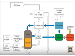
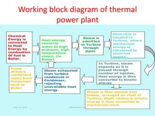
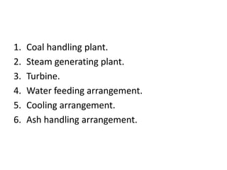
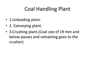
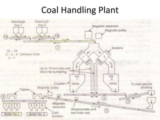
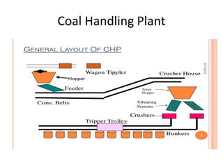
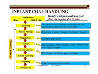
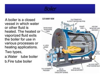
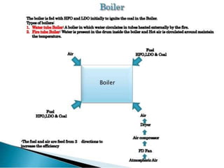
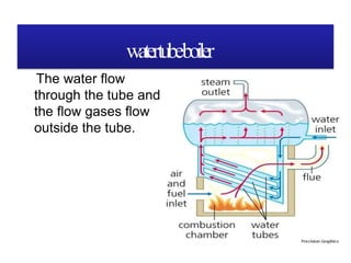
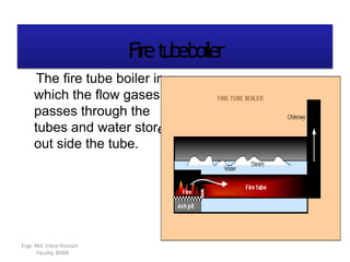
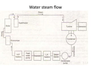
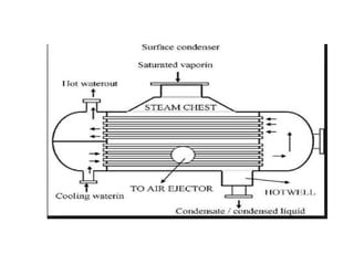
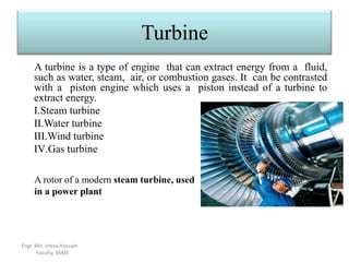
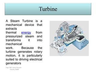
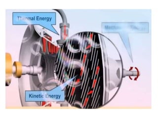
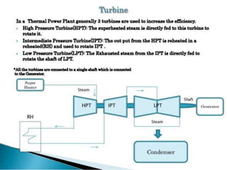
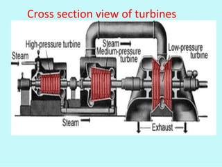
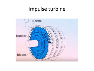
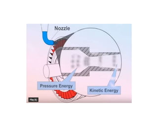
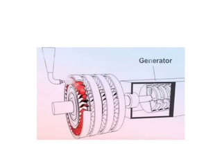
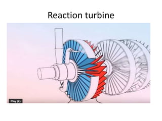
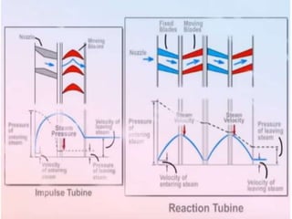
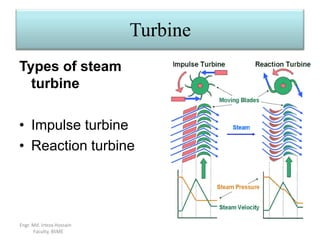
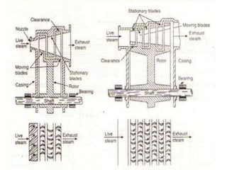
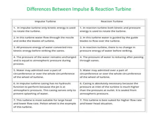
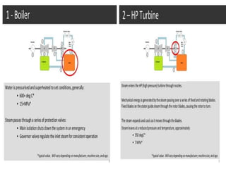
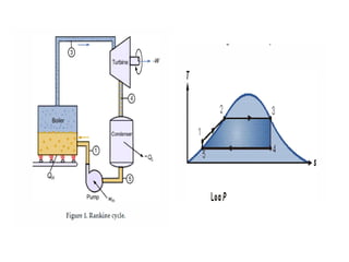
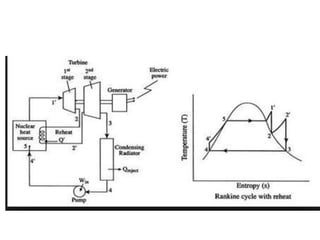
STEAM POWER PLANT
Layout of steam power plant
Working block diagram of thermal
power plant
1. Coal handling plant.
2. Steam generating plant.
3. Turbine.
4. Water feeding arrangement.
5. Cooling arrangement.
6. Ash handling arrangement.
Coal Handling Plant
• 1.Unloading plant.
• 2. Conveying plant.
• 3.Crushing plant.(Coal size of 19 mm and
below passes and remaining goes to the
crusher)
Coal Handling Plant
Coal Handling Plant
Boiler
A boiler is a closed
vessel in which water
or other fluid is
heated. The heated or
vaporized fluid exits
the boiler for use in
various processes or
heating applications.
Two types,
a.Water tube boiler
b.Fire tube boiler
watertubeboiler
The water flow
through the tube and
the flow gases flow
outside the tube.
Firetubeboiler
n
e
The fire tube boiler i
which the flow gases
passes through the
tubes and water stor
out side the tube.
Engr. Md. Irteza Hossain
Faculty, BSME
BoilerAccessories
Air Pre heater
Air pre heater is a heat
recovery unit . An air pre
heater is used to recover
the heat from the exhaust
flue gas.
BoilerAccessories
Super-heater A
super-
heater is a
device used to
convert
saturated steam
or wet steam
into dry steam
used in steam
engines
Engr. Md. IrtezaHossain
BoilerAccessories
Economizer
An economizer is a device
used to heat the feed water and
heat the condensate from
turbines before it is pumped to
the boilers by utilizing the heat
exhaust
leaving
flue gasses
through
in the
before
chimney.
Fig: Layout of Economizer.
Boiler Accessories
Economizer
The first successful economizer
design was used to increase the
steam-raising efficiency of the
boilers of stationary steam
engines. It was patented by
Edward Green in 1845.
•Economizers are commonly used
as part of a heat recovery steam
generator in a combined cycle
power plant.
• A common application of
economizers in steam power plants
is to capture the waste heat from
boiler stack gases (flue gas) and
transfer it to the boiler feed water.
This raises the temperature of the
boiler feed water
Boiler Accessories
Re-heater
Boiler Accessories
Engr. Md. Irteza Hossain
Faculty, BSME
Re-heater
Re-heaters are the same as the super-heaters but the temperature of
it’s a little bite less than super-heaters and their pressure is 20%-
25% less than the super-heater,
It usually use to elevate the steam temperature. After expanding
through the high pressure turbine the exhaust steam is returned to the
boiler at 360 C and 42 bar pressure for reheating before being used in
the intermediate pressure turbine.
The re-heater reheats the steam from a temperature of 360 C back to
568 C.
Flue gas flow arrangement
I.D Fan
• Induced Draft:- A fan is used to extract the air
from boiler post combustion via (Electrostatic
Precipitator if present) to exhaust through the
chimney. This is called ID fan
Feed Water Treatment
Water treatment plant flow
Free from
original
turbidity(alum+
lime solution)
Free from
suspended
impurities
Take up all the
metallic cations of
the mineral sat and
relese hydrogen ion
or acidity
Romove
CO2 from
water
Make Free from all
the anionic
impurities
Mix of cation and
anion exchange resin
Water steam flow
Turbine
A turbine is a type of engine that can extract energy from a fluid,
such as water, steam, air, or combustion gases. It can be contrasted
with a piston engine which uses a piston instead of a turbine to
extract energy.
I.Steam turbine
II.Water turbine
III.Wind turbine
IV.Gas turbine
A rotor of a modern steam turbine, used
in a power plant
Engr. Md. Irteza Hossain
Faculty, BSME
Turbine
Engr. Md. Irteza Hossain
Faculty, BSME
A Steam Turbine is a
mechanical device that
extracts
thermal energy from
pressurized steam and
transforms it into
mechanical
work. Because the
turbine generates rotary
motion, it is particularly
suited to driving electrical
generators
Cross section view of turbines
Impulse turbine
Reaction turbine
Turbine
Types of steam
turbine
• Impulse turbine
• Reaction turbine
Engr. Md. Irteza Hossain
Faculty, BSME
Differences Between Impulse & Reaction Turbine
Steam Turbine Cycle
Thermodynamics Cycles
Gas Cycles Vapour Cycles
Working Fluid remains in Gaseous
Phase throughout the Cycle.
Working Fluid exists in Vapor
Phase during part of the Cycle, and
in liquid phase during remaining
part.
Engr. Md. Irteza Hossain
Faculty, BSME
COOLING TOWERS
Rankine Cycle
• Basic Cycle
• The Rankine cycle is the fundamental operating cycle of all power plants where an operating
fluid is continuously evaporated and condensed. The selection of operating fluid depends
mainly on the available temperature range. Figure 1 shows the idealized Rankine cycle.
• The pressure-enthalpy (p-h) and temperature-entropy (T-s) diagrams of this cycle are given
in Figure 2. The Rankine cycle operates in the following steps:
• 1-2-3 Isobaric Heat Transfer. High pressure liquid enters the boiler from the feed pump (1)
and is heated to the saturation temperature (2). Further addition of energy causes evaporation
of the liquid until it is fully converted to saturated steam (3).
• 3-4 Isentropic Expansion. The vapor is expanded in the turbine, thus producing work which
may be converted to electricity. In practice, the expansion is limited by the temperature of the
cooling medium and by the erosion of the turbine blades by liquid entrainment in the vapor
stream as the process moves further into the two-phase region. Exit vapor qualities should be
greater than 90%.
• 4-5 Isobaric Heat Rejection. The vapor-liquid mixture leaving the turbine (4) is condensed at
low pressure, usually in a surface condenser using cooling water. In well designed and
maintained condensers, the pressure of the vapor is well below atmospheric pressure,
approaching the saturation pressure of the operating fluid at the cooling water temperature.
• 5-1 Isentropic Compression. The pressure of the condensate is raised in the feed pump.
Because of the low specific volume of liquids, the pump work is relatively small and often
neglected in thermodynamic calculations.
• https://www.youtube.com/watch?v=ChvI2v85
fsU

Steam turbine

  • 1.
  • 2.
    Layout of steampower plant
  • 3.
    Working block diagramof thermal power plant
  • 4.
    1. Coal handlingplant. 2. Steam generating plant. 3. Turbine. 4. Water feeding arrangement. 5. Cooling arrangement. 6. Ash handling arrangement.
  • 5.
    Coal Handling Plant •1.Unloading plant. • 2. Conveying plant. • 3.Crushing plant.(Coal size of 19 mm and below passes and remaining goes to the crusher)
  • 6.
  • 7.
  • 9.
    Boiler A boiler isa closed vessel in which water or other fluid is heated. The heated or vaporized fluid exits the boiler for use in various processes or heating applications. Two types, a.Water tube boiler b.Fire tube boiler
  • 11.
    watertubeboiler The water flow throughthe tube and the flow gases flow outside the tube.
  • 12.
    Firetubeboiler n e The fire tubeboiler i which the flow gases passes through the tubes and water stor out side the tube. Engr. Md. Irteza Hossain Faculty, BSME
  • 13.
    BoilerAccessories Air Pre heater Airpre heater is a heat recovery unit . An air pre heater is used to recover the heat from the exhaust flue gas.
  • 14.
    BoilerAccessories Super-heater A super- heater isa device used to convert saturated steam or wet steam into dry steam used in steam engines Engr. Md. IrtezaHossain
  • 15.
    BoilerAccessories Economizer An economizer isa device used to heat the feed water and heat the condensate from turbines before it is pumped to the boilers by utilizing the heat exhaust leaving flue gasses through in the before chimney. Fig: Layout of Economizer.
  • 16.
    Boiler Accessories Economizer The firstsuccessful economizer design was used to increase the steam-raising efficiency of the boilers of stationary steam engines. It was patented by Edward Green in 1845. •Economizers are commonly used as part of a heat recovery steam generator in a combined cycle power plant. • A common application of economizers in steam power plants is to capture the waste heat from boiler stack gases (flue gas) and transfer it to the boiler feed water. This raises the temperature of the boiler feed water
  • 17.
  • 18.
    Boiler Accessories Engr. Md.Irteza Hossain Faculty, BSME Re-heater Re-heaters are the same as the super-heaters but the temperature of it’s a little bite less than super-heaters and their pressure is 20%- 25% less than the super-heater, It usually use to elevate the steam temperature. After expanding through the high pressure turbine the exhaust steam is returned to the boiler at 360 C and 42 bar pressure for reheating before being used in the intermediate pressure turbine. The re-heater reheats the steam from a temperature of 360 C back to 568 C.
  • 19.
    Flue gas flowarrangement
  • 22.
    I.D Fan • InducedDraft:- A fan is used to extract the air from boiler post combustion via (Electrostatic Precipitator if present) to exhaust through the chimney. This is called ID fan
  • 23.
  • 24.
    Water treatment plantflow Free from original turbidity(alum+ lime solution) Free from suspended impurities Take up all the metallic cations of the mineral sat and relese hydrogen ion or acidity Romove CO2 from water Make Free from all the anionic impurities Mix of cation and anion exchange resin
  • 25.
  • 28.
    Turbine A turbine isa type of engine that can extract energy from a fluid, such as water, steam, air, or combustion gases. It can be contrasted with a piston engine which uses a piston instead of a turbine to extract energy. I.Steam turbine II.Water turbine III.Wind turbine IV.Gas turbine A rotor of a modern steam turbine, used in a power plant Engr. Md. Irteza Hossain Faculty, BSME
  • 29.
    Turbine Engr. Md. IrtezaHossain Faculty, BSME A Steam Turbine is a mechanical device that extracts thermal energy from pressurized steam and transforms it into mechanical work. Because the turbine generates rotary motion, it is particularly suited to driving electrical generators
  • 32.
    Cross section viewof turbines
  • 33.
  • 36.
  • 38.
    Turbine Types of steam turbine •Impulse turbine • Reaction turbine Engr. Md. Irteza Hossain Faculty, BSME
  • 40.
    Differences Between Impulse& Reaction Turbine
  • 45.
    Steam Turbine Cycle ThermodynamicsCycles Gas Cycles Vapour Cycles Working Fluid remains in Gaseous Phase throughout the Cycle. Working Fluid exists in Vapor Phase during part of the Cycle, and in liquid phase during remaining part. Engr. Md. Irteza Hossain Faculty, BSME
  • 46.
  • 66.
    Rankine Cycle • BasicCycle • The Rankine cycle is the fundamental operating cycle of all power plants where an operating fluid is continuously evaporated and condensed. The selection of operating fluid depends mainly on the available temperature range. Figure 1 shows the idealized Rankine cycle. • The pressure-enthalpy (p-h) and temperature-entropy (T-s) diagrams of this cycle are given in Figure 2. The Rankine cycle operates in the following steps: • 1-2-3 Isobaric Heat Transfer. High pressure liquid enters the boiler from the feed pump (1) and is heated to the saturation temperature (2). Further addition of energy causes evaporation of the liquid until it is fully converted to saturated steam (3). • 3-4 Isentropic Expansion. The vapor is expanded in the turbine, thus producing work which may be converted to electricity. In practice, the expansion is limited by the temperature of the cooling medium and by the erosion of the turbine blades by liquid entrainment in the vapor stream as the process moves further into the two-phase region. Exit vapor qualities should be greater than 90%. • 4-5 Isobaric Heat Rejection. The vapor-liquid mixture leaving the turbine (4) is condensed at low pressure, usually in a surface condenser using cooling water. In well designed and maintained condensers, the pressure of the vapor is well below atmospheric pressure, approaching the saturation pressure of the operating fluid at the cooling water temperature. • 5-1 Isentropic Compression. The pressure of the condensate is raised in the feed pump. Because of the low specific volume of liquids, the pump work is relatively small and often neglected in thermodynamic calculations.
  • 73.