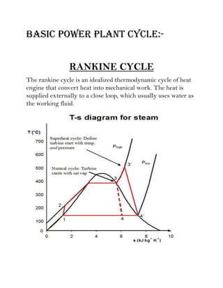
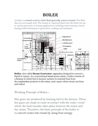
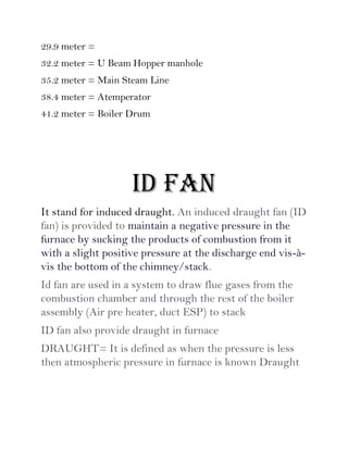
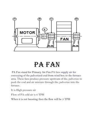
A power plant is an industrial facility that generates electricity using various energy sources such as hydro, nuclear, and thermal processes. The document details the components, working principles, and cycles involved in thermal power plants, specifically emphasizing the Rankine cycle, boiler function, and air handling systems. Additionally, it covers the importance of equipment like fans, electrostatic precipitators, and condensers in ensuring efficient power generation.