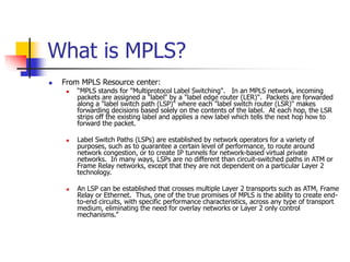
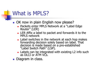
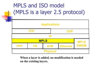
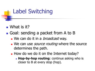
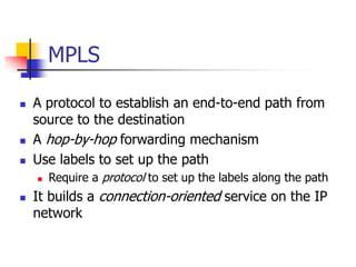
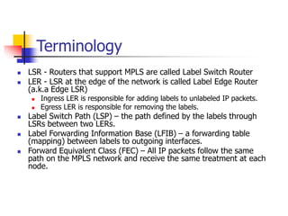
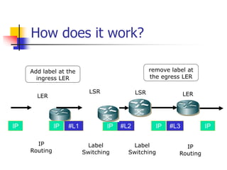
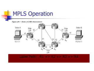
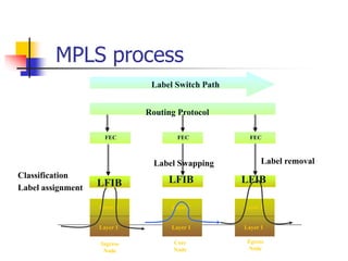
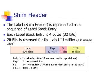
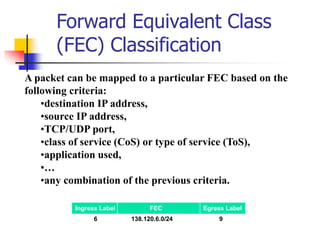
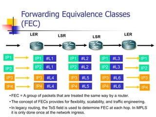
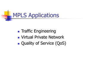
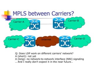
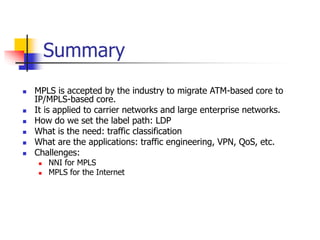
Multi-Protocol Label Switch
(MPLS)
Overview and short tutorial
Credits: Part of this
presentation is based on
James Yu lecture (Many
thanks!) and from MPLS
council web site
What is MPLS?
 From MPLS Resource center:
 “MPLS stands for "Multiprotocol Label Switching". In an MPLS network, incoming
packets are assigned a "label" by a "label edge router (LER)". Packets are forwarded
along a "label switch path (LSP)" where each "label switch router (LSR)" makes
forwarding decisions based solely on the contents of the label. At each hop, the LSR
strips off the existing label and applies a new label which tells the next hop how to
forward the packet.
 Label Switch Paths (LSPs) are established by network operators for a variety of
purposes, such as to guarantee a certain level of performance, to route around
network congestion, or to create IP tunnels for network-based virtual private
networks. In many ways, LSPs are no different than circuit-switched paths in ATM or
Frame Relay networks, except that they are not dependent on a particular Layer 2
technology.
 An LSP can be established that crosses multiple Layer 2 transports such as ATM, Frame
Relay or Ethernet. Thus, one of the true promises of MPLS is the ability to create end-
to-end circuits, with specific performance characteristics, across any type of transport
medium, eliminating the need for overlay networks or Layer 2 only control
mechanisms.”
What is MPLS?
 OK now in plain English now please?
 Packets enter MPLS Network at a “Label Edge
Router” (LER)
 LER Affix a label to packet and forwards it to the
MPLS network
 Label switches in the network at each hop makes
forwarding decision solely based on label. That
decision is made based on a pre-established
“Label Switch Path” (LSP).
 Labels can be integrated with existing L2 info such
as DLCI or ATM VCs.
 Diagram in class.
MPLS Motivation
 Original drivers towards label
switching:
 Designed to make routers faster
 ATM switches were faster than routers
 Fixed length label lookup faster than longest match used
by IP routing
 Allow a device to do the same job as a router with
performance of ATM switch
 Enabled IP + ATM integration
 Mapping of IP to ATM had become very complex, hence
simplify by replacing ATM signalling protocols with IP
control protocols
MPLS Motivation
 Growth and evolution of the Internet
 The need to evolve routing algorithm
 The need for advanced forwarding algorithm
 routing vs. forwarding (switching)
 routing: flexibility
 forwarding: price/performance
 Can we forward/switch IP packets?
 Allow speed of L2 switching at L3
 Router makes L3 forwarding decision based on a single field:
similar to L2 forwarding  Sppppppeeeeed
Some MPLS Benefits
 Traffic Engineering - the ability to set the path traffic will take through the
network, and the ability to set performance characteristics for a class of traffic
 VPNs - using MPLS, service providers can create IP tunnels throughout their
network, without the need for encryption or end-user applications
 Layer 2 Transport - New standards being defined by the IETF's PWE3 and
PPVPN working groups allow service providers to carry Layer 2 services including
Ethernet, Frame Relay and ATM over an IP/MPLS core
 Elimination of Multiple Layers - Typically most carrier networks employ an
overlay model where SONET/SDH is deployed at Layer 1, ATM is used at Layer 2
and IP is used at Layer 3. Using MPLS, carriers can migrate many of the
functions of the SONET/SDH and ATM control plane to Layer 3, thereby
simplifying network management and network complexity. Eventually, carrier
networks may be able to migrate away from SONET/SDH and ATM all-together,
which means elimination of ATM's inherent "cell-tax" in carrying IP traffic.
MPLS History
 IP over ATM
 IP Switching by Ipsilon
 Cell Switching Router (CSR) by Toshiba
 Tag switching by Cisco
 Aggregate Route-based IP Switching (IBM)
 IETF – MPLS
 http://www.ietf.org/html.charters/mpls-charter.html
 RFC3031 – MPLS Architecture
 RFC2702 – Requirements for TE over MPLS
 RFC3036 – LDP Specification
MPLS and ISO model
(MPLS is a layer 2.5 protocol)
Physical
IP
Applications
TCP UDP
PPP FR ATM
MPLS
When a layer is added, no modification is needed
on the existing layers.
Ethernet
MPS
DWDM
Label Switching
 What is it?
 Goal: sending a packet from A to B
 We can do it in a broadcast way.
 We can use source routing where the source
determines the path.
 How do we do it on the Internet today?
 Hop-by-hop routing: continue asking who is
closer to B at every stop (hop).
Using Label on the network
(This is not new!)
 ATM: VPI/VCI
 Frame Relay: DLCI
 X.25: LCI (logical Channel Identifier)
 TDM: the time slot (Circuit Identification
Code)
 Ethernet switching: ???
Q: do you see any commonality of these labels?
Label Substitution (swapping)
Label-A1 Label-B1
Label-A2
Label-A3
Label-A4
Label-B2
Label-B3
Label-B4
MPLS
 A protocol to establish an end-to-end path from
source to the destination
 A hop-by-hop forwarding mechanism
 Use labels to set up the path
 Require a protocol to set up the labels along the path
 It builds a connection-oriented service on the IP
network
Terminology
 LSR - Routers that support MPLS are called Label Switch Router
 LER - LSR at the edge of the network is called Label Edge Router
(a.k.a Edge LSR)
 Ingress LER is responsible for adding labels to unlabeled IP packets.
 Egress LER is responsible for removing the labels.
 Label Switch Path (LSP) – the path defined by the labels through
LSRs between two LERs.
 Label Forwarding Information Base (LFIB) – a forwarding table
(mapping) between labels to outgoing interfaces.
 Forward Equivalent Class (FEC) – All IP packets follow the same
path on the MPLS network and receive the same treatment at each
node.
How does it work?
IP IP #L1 IP #L2 IP #L3 IP
LSR LSR
LER LER
IP
Routing
IP
Routing
Label
Switching
Label
Switching
Add label at the
ingress LER
remove label at
the egress LER
MPLS Operation
Label Path: R1 => R2 => R3 => R4
Label Forwarding Information
Base (LFIB)
Router Incoming
Label
Incoming
Interface
Destination
Network
(FEC)
Outgoing
Interface
Outgoing
Label
R1 --- E0 172.16.1.0
S1 6
R2 6 S0 172.16.1.0
S2 11
R3 11 S0 172.16.1.0
S3 7
R4 7 S1 172.26.1.0
E0 --
Q: create LFIB for R4 => R3 => R2 => R1
Label removal
Classification
Label assignment
Routing Protocol
Label Switch Path
LFIB
Ingress
Node
Core
Node
Egress
Node
Layer 2
Layer 1
Layer 2
Layer 1
Layer 2
Layer 1
LFIB
Layer 2
Layer 1
Layer 2
Layer 1
FEC FEC FEC
MPLS process
LFIB
Label Swapping
Label Encapsulation
Label information can be carried in a packet in a variety of ways:
 A small, shim label header inserted between the Layer 2 and
network layer headers.
 As part of the Layer 2 header, if the Layer 2 header provides
adequate semantics (such as ATM).
 As part of the network layer header (future, such as IPv6).
 In general, MPLS can be implemented over any media type,
including point-to-point, Ethernet, Frame Relay, and ATM links. The
label-forwarding component is independent of the network layer
protocol.
Label Encapsulation
ATM FR Ethernet PPP
MPLS Encapsulation is specified over various media
types. Labels may use existing format (e.g., VPI/VCI)
or use a new shim label format.
VPI/VCI DLCI Shim Label
L2
Label
Datagram
IP
Header
Label
L2
Header
Shim Header
 The Label (Shim Header) is represented as a
sequence of Label Stack Entry
 Each Label Stack Entry is 4 bytes (32 bits)
 20 Bits is reserved for the Label Identifier (also named
Label)
Label
(20 bits)
Exp
(3 bits)
S
(1 bit)
TTL
(8bits)
Label : Label value (0 to 15 are reserved for special use)
Exp : Experimental Use
S : Bottom of Stack (set to 1 for the last entry in the label)
TTL : Time To Live
Ingress Label FEC Egress Label
6 138.120.6.0/24 9
A packet can be mapped to a particular FEC based on the
following criteria:
•destination IP address,
•source IP address,
•TCP/UDP port,
•class of service (CoS) or type of service (ToS),
•application used,
•…
•any combination of the previous criteria.
Forward Equivalent Class
(FEC) Classification
Forwarding Equivalence Classes
(FEC)
•FEC = A group of packets that are treated the same way by a router.
•The concept of FECs provides for flexibility, scalability, and traffic engineering.
•In legacy routing, the ToS field is used to determine FEC at each hop. In MPLS
it is only done once at the network ingress.
IP1
IP2
IP1
IP2
LSR
LSR
LER LER
IP1 #L1
IP2 #L1
IP1 #L2
IP2 #L2
IP1 #L3
IP2 #L3
IP3
IP4
IP3
IP4
IP3 #L4
IP4 #L4
IP3 #L5
IP4 #L5
IP3 #L6
IP4 #L6
MPLS Applications
 Traffic Engineering
 Virtual Private Network
 Quality of Service (QoS)
Traffic Engineering
 Traffic engineering allows a network administrator to make the path
deterministic and bypass the normal routed hop-by-hop paths. An
administrator may elect to explicitly define the path between stations to
ensure QoS or have the traffic follow a specified path to reduce traffic
loading across certain hops.
 The network administrator can reduce congestion by forcing the frame to
travel around the overloaded segments. Traffic engineering, then, enables
an administrator to define a policy for forwarding frames rather than
depending upon dynamic routing protocols.
 Traffic engineering is similar to source-routing in that an explicit path is
defined for the frame to travel. However, unlike source-routing, the hop-by-
hop definition is not carried with every frame. Rather, the hops are
configured in the LSRs ahead of time along with the appropriate label
values.
MPLS – Traffic Engineering
 End-to-End forwarding decision determined by
ingress node.
 Enables Traffic Engineering
LER 1
LSR 2 LSR 3
LER 4
L
IP
Forward to
LSR 2
LSR 3
LSR 4
LSR X
Overload !!
Overload !!
IP
IP
L
IP
L
IP
MPLS-based VPN
 One of most popular MPLS applications is the
implementation of VPN.
 The basic concept is the same as ATM transparent LAN.
 Using label (instead of IP address) to interconnect
multiple sites over a carrier’s network. Each site has its
own private IP address space.
 Different VPNs may use the same IP address space.
 Same as Frame Relay separation of different user
traffic… but more” fashionable” to use word “VPN” today.
MPLS VPN Connection Model
VPN_A
VPN_A
VPN_B
10.3.0.0
10.1.0.0
11.5.0.0
VPN_A
VPN_B
VPN_B
10.1.0.0
10.2.0.0
11.6.0.0
VPN_A
10.2.0.0
MPLS Core
VPN_A: 10.2.0.0/24, 11.6.0.0/24, 11.5.0.0/24
VPN_B: 10.2.0.0/24, 10.1.0.0/24, 10.3.0.0/24
MPLS
Edge
MPLS
Edge
MPLS VPN - Example
192.168.1.0 192.168.2.0
192.168.3.0 192.168.4.0
-- E1 10 E3
-- E2 20 E3
10 E1 30 E2
20 E1 40 E2
30 E3 -- E1
40 E3 -- E2
E1
E2
E1
E2
-- E1 50 E3
-- E2 60 E3
50 E2 70 E1
60 E2 80 E1
70 E3 -- E1
80 E3 -- E1
LSP
LSP
E3
E1 E2
E3
MPLS and QoS
 An important proposed MPLS capability is quality of service (QoS) support.
 QoS mechanisms:
 Pre-configuration based on physical interface
 Classification of incoming packets into different classes
 Classification based on network characteristics (such as congestion, throughput,
delay, and loss)
 A label corresponding to the resultant class is applied to the packet.
 Labeled packets are handled by LSRs in their path without needing to be
reclassified.
 MPLS enables simple logic to find the state that identifies how the packet
should be scheduled.
 The exact use of MPLS for QoS purposes depends a great deal on how QoS
is deployed.
 Support various QoS protocols, such as IntServ, DiffServ, and RSVP.
FEC QoS Classification
LER
MPLS label based on
1. physical interface
2. Source IP address
3. Destination IP address
4. Type of Service (ToS)
5. Protocol information
6. etc.
LSR
A priority scheme for
different label switch path (LSP)
IP Differentiated Model
Version
Length
Layer 3
IPV4
Data
ToS
1 Byte
0
7 1
2
3
4
5
6
IP Precedence Unused
Bits;
0 1 2 3
0 1 2 3 4 5 6 7 8 9 0 1 2 3 4 5 6 7 8 9 0 1 2 3 4 5 6 7 8 9 0 1
+-+-+-+-+-+-+-+-+-+-+-+-+-+-+-+-+-+-+-+-+-+-+-+-+-+-+-+-+-+-+-+-+
+-+-+-+-+-+-+-+-+-+-+-+-+-+-+-+-+-+-+-+-+-+-+-+-+-+-+-+-+-+-+-+-+
| Label | EXP |S| TTL |
other IP header info
Internet
MPLS between Carriers?
Carrier-A
Carrier-B
Carrier-C Carrier-D
Q: Does LDP work on different carriers’ network?
A (short): not yet
A (long): no network-to-network interface (NNI) signaling
.. And I really don’t expect it in the near future…
Summary
 MPLS is accepted by the industry to migrate ATM-based core to
IP/MPLS-based core.
 It is applied to carrier networks and large enterprise networks.
 How do we set the label path: LDP
 What is the need: traffic classification
 What are the applications: traffic engineering, VPN, QoS, etc.
 Challenges:
 NNI for MPLS
 MPLS for the Internet

MPLS-jpl.ppt

  • 1.
    Multi-Protocol Label Switch (MPLS) Overviewand short tutorial Credits: Part of this presentation is based on James Yu lecture (Many thanks!) and from MPLS council web site
  • 2.
    What is MPLS? From MPLS Resource center:  “MPLS stands for "Multiprotocol Label Switching". In an MPLS network, incoming packets are assigned a "label" by a "label edge router (LER)". Packets are forwarded along a "label switch path (LSP)" where each "label switch router (LSR)" makes forwarding decisions based solely on the contents of the label. At each hop, the LSR strips off the existing label and applies a new label which tells the next hop how to forward the packet.  Label Switch Paths (LSPs) are established by network operators for a variety of purposes, such as to guarantee a certain level of performance, to route around network congestion, or to create IP tunnels for network-based virtual private networks. In many ways, LSPs are no different than circuit-switched paths in ATM or Frame Relay networks, except that they are not dependent on a particular Layer 2 technology.  An LSP can be established that crosses multiple Layer 2 transports such as ATM, Frame Relay or Ethernet. Thus, one of the true promises of MPLS is the ability to create end- to-end circuits, with specific performance characteristics, across any type of transport medium, eliminating the need for overlay networks or Layer 2 only control mechanisms.”
  • 3.
    What is MPLS? OK now in plain English now please?  Packets enter MPLS Network at a “Label Edge Router” (LER)  LER Affix a label to packet and forwards it to the MPLS network  Label switches in the network at each hop makes forwarding decision solely based on label. That decision is made based on a pre-established “Label Switch Path” (LSP).  Labels can be integrated with existing L2 info such as DLCI or ATM VCs.  Diagram in class.
  • 4.
    MPLS Motivation  Originaldrivers towards label switching:  Designed to make routers faster  ATM switches were faster than routers  Fixed length label lookup faster than longest match used by IP routing  Allow a device to do the same job as a router with performance of ATM switch  Enabled IP + ATM integration  Mapping of IP to ATM had become very complex, hence simplify by replacing ATM signalling protocols with IP control protocols
  • 5.
    MPLS Motivation  Growthand evolution of the Internet  The need to evolve routing algorithm  The need for advanced forwarding algorithm  routing vs. forwarding (switching)  routing: flexibility  forwarding: price/performance  Can we forward/switch IP packets?  Allow speed of L2 switching at L3  Router makes L3 forwarding decision based on a single field: similar to L2 forwarding  Sppppppeeeeed
  • 6.
    Some MPLS Benefits Traffic Engineering - the ability to set the path traffic will take through the network, and the ability to set performance characteristics for a class of traffic  VPNs - using MPLS, service providers can create IP tunnels throughout their network, without the need for encryption or end-user applications  Layer 2 Transport - New standards being defined by the IETF's PWE3 and PPVPN working groups allow service providers to carry Layer 2 services including Ethernet, Frame Relay and ATM over an IP/MPLS core  Elimination of Multiple Layers - Typically most carrier networks employ an overlay model where SONET/SDH is deployed at Layer 1, ATM is used at Layer 2 and IP is used at Layer 3. Using MPLS, carriers can migrate many of the functions of the SONET/SDH and ATM control plane to Layer 3, thereby simplifying network management and network complexity. Eventually, carrier networks may be able to migrate away from SONET/SDH and ATM all-together, which means elimination of ATM's inherent "cell-tax" in carrying IP traffic.
  • 7.
    MPLS History  IPover ATM  IP Switching by Ipsilon  Cell Switching Router (CSR) by Toshiba  Tag switching by Cisco  Aggregate Route-based IP Switching (IBM)  IETF – MPLS  http://www.ietf.org/html.charters/mpls-charter.html  RFC3031 – MPLS Architecture  RFC2702 – Requirements for TE over MPLS  RFC3036 – LDP Specification
  • 8.
    MPLS and ISOmodel (MPLS is a layer 2.5 protocol) Physical IP Applications TCP UDP PPP FR ATM MPLS When a layer is added, no modification is needed on the existing layers. Ethernet MPS DWDM
  • 9.
    Label Switching  Whatis it?  Goal: sending a packet from A to B  We can do it in a broadcast way.  We can use source routing where the source determines the path.  How do we do it on the Internet today?  Hop-by-hop routing: continue asking who is closer to B at every stop (hop).
  • 10.
    Using Label onthe network (This is not new!)  ATM: VPI/VCI  Frame Relay: DLCI  X.25: LCI (logical Channel Identifier)  TDM: the time slot (Circuit Identification Code)  Ethernet switching: ??? Q: do you see any commonality of these labels?
  • 11.
    Label Substitution (swapping) Label-A1Label-B1 Label-A2 Label-A3 Label-A4 Label-B2 Label-B3 Label-B4
  • 12.
    MPLS  A protocolto establish an end-to-end path from source to the destination  A hop-by-hop forwarding mechanism  Use labels to set up the path  Require a protocol to set up the labels along the path  It builds a connection-oriented service on the IP network
  • 13.
    Terminology  LSR -Routers that support MPLS are called Label Switch Router  LER - LSR at the edge of the network is called Label Edge Router (a.k.a Edge LSR)  Ingress LER is responsible for adding labels to unlabeled IP packets.  Egress LER is responsible for removing the labels.  Label Switch Path (LSP) – the path defined by the labels through LSRs between two LERs.  Label Forwarding Information Base (LFIB) – a forwarding table (mapping) between labels to outgoing interfaces.  Forward Equivalent Class (FEC) – All IP packets follow the same path on the MPLS network and receive the same treatment at each node.
  • 14.
    How does itwork? IP IP #L1 IP #L2 IP #L3 IP LSR LSR LER LER IP Routing IP Routing Label Switching Label Switching Add label at the ingress LER remove label at the egress LER
  • 15.
    MPLS Operation Label Path:R1 => R2 => R3 => R4
  • 16.
    Label Forwarding Information Base(LFIB) Router Incoming Label Incoming Interface Destination Network (FEC) Outgoing Interface Outgoing Label R1 --- E0 172.16.1.0 S1 6 R2 6 S0 172.16.1.0 S2 11 R3 11 S0 172.16.1.0 S3 7 R4 7 S1 172.26.1.0 E0 -- Q: create LFIB for R4 => R3 => R2 => R1
  • 17.
    Label removal Classification Label assignment RoutingProtocol Label Switch Path LFIB Ingress Node Core Node Egress Node Layer 2 Layer 1 Layer 2 Layer 1 Layer 2 Layer 1 LFIB Layer 2 Layer 1 Layer 2 Layer 1 FEC FEC FEC MPLS process LFIB Label Swapping
  • 18.
    Label Encapsulation Label informationcan be carried in a packet in a variety of ways:  A small, shim label header inserted between the Layer 2 and network layer headers.  As part of the Layer 2 header, if the Layer 2 header provides adequate semantics (such as ATM).  As part of the network layer header (future, such as IPv6).  In general, MPLS can be implemented over any media type, including point-to-point, Ethernet, Frame Relay, and ATM links. The label-forwarding component is independent of the network layer protocol.
  • 19.
    Label Encapsulation ATM FREthernet PPP MPLS Encapsulation is specified over various media types. Labels may use existing format (e.g., VPI/VCI) or use a new shim label format. VPI/VCI DLCI Shim Label L2 Label Datagram IP Header Label L2 Header
  • 20.
    Shim Header  TheLabel (Shim Header) is represented as a sequence of Label Stack Entry  Each Label Stack Entry is 4 bytes (32 bits)  20 Bits is reserved for the Label Identifier (also named Label) Label (20 bits) Exp (3 bits) S (1 bit) TTL (8bits) Label : Label value (0 to 15 are reserved for special use) Exp : Experimental Use S : Bottom of Stack (set to 1 for the last entry in the label) TTL : Time To Live
  • 21.
    Ingress Label FECEgress Label 6 138.120.6.0/24 9 A packet can be mapped to a particular FEC based on the following criteria: •destination IP address, •source IP address, •TCP/UDP port, •class of service (CoS) or type of service (ToS), •application used, •… •any combination of the previous criteria. Forward Equivalent Class (FEC) Classification
  • 22.
    Forwarding Equivalence Classes (FEC) •FEC= A group of packets that are treated the same way by a router. •The concept of FECs provides for flexibility, scalability, and traffic engineering. •In legacy routing, the ToS field is used to determine FEC at each hop. In MPLS it is only done once at the network ingress. IP1 IP2 IP1 IP2 LSR LSR LER LER IP1 #L1 IP2 #L1 IP1 #L2 IP2 #L2 IP1 #L3 IP2 #L3 IP3 IP4 IP3 IP4 IP3 #L4 IP4 #L4 IP3 #L5 IP4 #L5 IP3 #L6 IP4 #L6
  • 23.
    MPLS Applications  TrafficEngineering  Virtual Private Network  Quality of Service (QoS)
  • 24.
    Traffic Engineering  Trafficengineering allows a network administrator to make the path deterministic and bypass the normal routed hop-by-hop paths. An administrator may elect to explicitly define the path between stations to ensure QoS or have the traffic follow a specified path to reduce traffic loading across certain hops.  The network administrator can reduce congestion by forcing the frame to travel around the overloaded segments. Traffic engineering, then, enables an administrator to define a policy for forwarding frames rather than depending upon dynamic routing protocols.  Traffic engineering is similar to source-routing in that an explicit path is defined for the frame to travel. However, unlike source-routing, the hop-by- hop definition is not carried with every frame. Rather, the hops are configured in the LSRs ahead of time along with the appropriate label values.
  • 25.
    MPLS – TrafficEngineering  End-to-End forwarding decision determined by ingress node.  Enables Traffic Engineering LER 1 LSR 2 LSR 3 LER 4 L IP Forward to LSR 2 LSR 3 LSR 4 LSR X Overload !! Overload !! IP IP L IP L IP
  • 26.
    MPLS-based VPN  Oneof most popular MPLS applications is the implementation of VPN.  The basic concept is the same as ATM transparent LAN.  Using label (instead of IP address) to interconnect multiple sites over a carrier’s network. Each site has its own private IP address space.  Different VPNs may use the same IP address space.  Same as Frame Relay separation of different user traffic… but more” fashionable” to use word “VPN” today.
  • 27.
    MPLS VPN ConnectionModel VPN_A VPN_A VPN_B 10.3.0.0 10.1.0.0 11.5.0.0 VPN_A VPN_B VPN_B 10.1.0.0 10.2.0.0 11.6.0.0 VPN_A 10.2.0.0 MPLS Core VPN_A: 10.2.0.0/24, 11.6.0.0/24, 11.5.0.0/24 VPN_B: 10.2.0.0/24, 10.1.0.0/24, 10.3.0.0/24 MPLS Edge MPLS Edge
  • 28.
    MPLS VPN -Example 192.168.1.0 192.168.2.0 192.168.3.0 192.168.4.0 -- E1 10 E3 -- E2 20 E3 10 E1 30 E2 20 E1 40 E2 30 E3 -- E1 40 E3 -- E2 E1 E2 E1 E2 -- E1 50 E3 -- E2 60 E3 50 E2 70 E1 60 E2 80 E1 70 E3 -- E1 80 E3 -- E1 LSP LSP E3 E1 E2 E3
  • 29.
    MPLS and QoS An important proposed MPLS capability is quality of service (QoS) support.  QoS mechanisms:  Pre-configuration based on physical interface  Classification of incoming packets into different classes  Classification based on network characteristics (such as congestion, throughput, delay, and loss)  A label corresponding to the resultant class is applied to the packet.  Labeled packets are handled by LSRs in their path without needing to be reclassified.  MPLS enables simple logic to find the state that identifies how the packet should be scheduled.  The exact use of MPLS for QoS purposes depends a great deal on how QoS is deployed.  Support various QoS protocols, such as IntServ, DiffServ, and RSVP.
  • 30.
    FEC QoS Classification LER MPLSlabel based on 1. physical interface 2. Source IP address 3. Destination IP address 4. Type of Service (ToS) 5. Protocol information 6. etc. LSR A priority scheme for different label switch path (LSP)
  • 31.
    IP Differentiated Model Version Length Layer3 IPV4 Data ToS 1 Byte 0 7 1 2 3 4 5 6 IP Precedence Unused Bits; 0 1 2 3 0 1 2 3 4 5 6 7 8 9 0 1 2 3 4 5 6 7 8 9 0 1 2 3 4 5 6 7 8 9 0 1 +-+-+-+-+-+-+-+-+-+-+-+-+-+-+-+-+-+-+-+-+-+-+-+-+-+-+-+-+-+-+-+-+ +-+-+-+-+-+-+-+-+-+-+-+-+-+-+-+-+-+-+-+-+-+-+-+-+-+-+-+-+-+-+-+-+ | Label | EXP |S| TTL | other IP header info
  • 32.
    Internet MPLS between Carriers? Carrier-A Carrier-B Carrier-CCarrier-D Q: Does LDP work on different carriers’ network? A (short): not yet A (long): no network-to-network interface (NNI) signaling .. And I really don’t expect it in the near future…
  • 33.
    Summary  MPLS isaccepted by the industry to migrate ATM-based core to IP/MPLS-based core.  It is applied to carrier networks and large enterprise networks.  How do we set the label path: LDP  What is the need: traffic classification  What are the applications: traffic engineering, VPN, QoS, etc.  Challenges:  NNI for MPLS  MPLS for the Internet