Download to read offline
![Amit, Mr. Shamsher Singh / International Journal of Engineering Research and Applications
(IJERA) ISSN: 2248-9622 www.ijera.com
Vol. 2, Issue 5, September- October 2012, pp.112-115
B) MPLS Header: II LITERATURE SURVEY
MPLS sticks a 32 bit Header as shown below: MPLS-TP ring protection mechanisms as a
Label (20 Bits): Carries information about novel protection mechanism, which aggregates merits
setting up the LSP based on a given FEC. Either of both wrapping and steering approaches, and which
Manual configuration or inserted on the basis of reduces packet loss significantly in case of in order
static or dynamic routing protocol delivery. The present article describes the
COS (3 bits):Defines the required Class of implementation in detail and shows that the new
Service. With 3 bits, 8 possible classes. Affects approach highly reduces packet loss compared to the
the Queuing and discard algorithms as the packet current mechanism[1]. A new architecture for MPLS-
travels through the Network. Some times it is based micro mobility management. Presented
copied from the IP Header TOS field. proposal called Optimized Integrated-Multi-Protocol
S (STACK) ( 1 BIT): MPLS supports multiple Label Switching (Optimized I-NMLPLS). Optimized
Labels. The processing of labelled stack is I-NMPLS is a hierarchical approach to support
always based on the top stack. We shall study micro-mobility. This approach integrates the traffic
this feature of MPLS in more detail shortly. engineering and QoS capabilities of MPLS with
TTL (Time To Live) ( 8 bits): Same function as Mobile IP Fast Authentication protocol (MIFA) as a
TTL in the IP Header. The packet is killed after mobility management framework. The integration
travelling the specified number of hops and if the between N1LPLS and MIFA is achieved through
packet has still not reached is destination. integration of MIFA control messages with MPLS
signalling traffic[2]. MPLS is a next generation
In today’s network world the advancement backbone architecture, it can speed up packet
of the network infrastructure is the sound base that forwarding to destination by label switching.
networks must rely on to compete in society. MPLS However, if there exists no backup LSP when the
offers that sound base at a lower cost and with primary LSP fails, MPLS frames cannot be
enhanced flexibility. It not only can use pre-existing forwarded to destination. Therefore, fault recovery
equipment used for technologies such as ATM and has become an important research area in MPLS
Frame Relay, but it allows the fine tuning of more Traffic Engineering[3]. A MPLS based routing
advanced technologies such as VoIP or video algorithm is present for reducing the number of
conferencing. Versatility and redundancy is what MPLS labels to N + M without increasing any link
makes a network reliable and flexible, and MPLS can load. Presented explicit N + M bound makes it easy
offer those solutions. It is not a matter of to limit the table size requirement for a planed
consideration; it is a matter of time and necessity in network, and the linearity allows for tables
world today. implemented in fast memory. For differentiated
services with K traffic classes with different load
C) MPLS-TP constraints, Presented bound increases to K(N+M).
Tomorrow's network will mostly carry Presented stack-depth is only one, justifying
packets. As a result, an evolution of existing time- implementations of MPLS with limited stack-
division multiplexing (TDM)-based transport depth[4].
networks is taking place, and new architectures This paper describes design,
optimized to carry packets are being defined. The implementation, and capability of a MPLS simulator,
function of a transport network is to carry which suppaas label swapping operation, LDP, CR-
information between service edge devices. These LDP, and various sorts of label distribution function.
devices could be Digital Subscriber Line Access It enables researchers to simulate how a U P is
Multiplexers (DSLAMs), gateways, T1/E1 established and terminated, and how the labelled
aggregators, broadband remote access servers packets act on the LSP. In order to show MPLS
(BRAS), etc. Traditional transport systems based on simulator's capability, the basic MPLS function
SDH/SONET platforms provide low-speed defined in MPLS standards is simulated; label
bandwidth granularity network services as well as distribution schemes, flow aggregation, ER-LSP, and
high-speed long-haul transmission services. Circuit- LSP Tunnel[5]. They introduces a T-MPLS
switched transport network services with fixed simulation tool developed using OPNET modeler
bandwidth granularity (64 Kbps, 1.5 Mbps, 2 Mbps, 11.5. Author proposed a simulation node structure
50 Mbps, 150 Mbps, 600 Mbps, etc.) were emulated including four layers, i.e. Client Layer, Adaptation
using connection-oriented, packet-switched (CO-PS) Layer, Control Layer and the Switching &
technologies and similar managed-bandwidth Forwarding Layer. All the L2 (PDH, SONET/SDH,
services. However, in the access/aggregation and ETH, FR, ATM, etc) and L3 (IP) payload could be
metro domains, there is a desire by carriers to mapped into T-MPLS tunnel through either MPLS
simplify packet transport networking in order to encapsulated method or pseudo wire mechanism[6].
reduce capital expenditures (CapEx) and operational Author provide some performance measurements
expenses (OpEx) in their next-generation comparing the prototype to software routers. The
networks.[5] measurements indicate that the prototype is an
113 | P a g e](https://image.slidesharecdn.com/v25112115-121016014813-phpapp02/85/V25112115-2-320.jpg)
![Amit, Mr. Shamsher Singh / International Journal of Engineering Research and Applications
(IJERA) ISSN: 2248-9622 www.ijera.com
Vol. 2, Issue 5, September- October 2012, pp.112-115
appropriate tool for achieving line speed forwarding
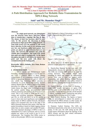
in testbeds and other experimental networks[7] A Establish the MPLS network in Ring topology
work on Mobile MPLS with Route Optimization is
presented by the author and proposes a route
optimization protocol to overcome this problem
in Mobile MPLS. By adding a correspondent
Establish the Save points over the network at
agent function to Mobile MPLS's edge routers,
equal distances from nods
the mobility binding of a mobile node can be
cached by the edge routers and the packet
routing to the mobile node can be route-
optimized[8]. Another work present an innovative
multi-service testbed for MPLS-TP networks to Store the transmission information on Save Points
demonstrate the transport performance of
interconnected rings. By validating dual-label and
two extended protection schemes, hardware
experimental results are given to show their
influences on transport[9].
Implement broken link or packet drop at random
location over the network
III RESEARCH METHODOLOGY
The proposed work is about to analyze the
network for the network fault and provide the
network restoration scheme by defining the
alternative path. The work also includes the Detect the packet drop and pass the information
distribution of substituted path notification among all to nearest save point
nodes over the network. The network reliability
depends on how accurately the fault information is
defined and the QOS depends on the efficient
distribution of notification over the network. Instruct source to stop the communication and
retransmit data from backup channel set this
In the existing methodology as the packet channel as main channel
loss is detected in such network it is detected by the
last save point that the information is lost. Now the
save point will regenerate the packet and send it in
the opposite direction and from the other path the
communication will be performed. But the main As the link reconstructed start using same channel
drawback of this approach is the complete re-routing for communication
process in worst case. It means if the data will be lost
near to the destination node and save point performs
the communication from reverse direction. Now the
packet has to travel the complete cycle again. The
overall algorithm for the proposed work is presented As the link reconstructed start using same channel
in the form of a flowchart given as under. for communication
Analyse the throughput
Figure 2: Proposed Methodology
Figure 2 shows the complete architecture of MPLS
network. In this proposed work we are defining a 2
Lane System for the network communication. The
properties of proposed system are
The proposed system is a 2 Lane
system.
Each Channel can send or receive data.
Both channels are independent to the
communication.
114 | P a g e](https://image.slidesharecdn.com/v25112115-121016014813-phpapp02/85/V25112115-3-320.jpg)
![Amit, Mr. Shamsher Singh / International Journal of Engineering Research and Applications
(IJERA) ISSN: 2248-9622 www.ijera.com
Vol. 2, Issue 5, September- October 2012, pp.112-115
Second channel is defined as the backup [7] Ali Diab, Rene Boringer, “Optimized I-
channel. MPLS: A Fast and Transparent Micro-
The main communication will be Mobility-Enabled MPLS
performed using main channel. Framework”, 1-4244-0398-7/06 §2006 IEEE
As the packet loss detected by the save [8] Yimin Qiu, “A Research of MPLS-based
point. Channel 2 will be selected for the Network Fault Recovery”, 2010 Third
data communication. International Conference on Intelligent
Same Save point will control both Networks and Intelligent Systems 978-0-
channel. 7695-4249-2/10 © 2010 IEEE
If the packet loss occur in second [9] David Applegate, “Load optimal MPLS
channel also then it will chose the routing with N + M labels”, 0-7803-
traditional approach to move in opposite 7753-2/03 (C) 2003 IEEE
direction and perform the [10] Gaeil Ahn and Woojik Chun, ” Design and
communication Implementation of MPLS Network
Simulator Supporting LDP and CR-LDP”,
IV CONCLUSION 0-7695-0777-8/00 0 2000 IEEE
The proposed work is the improvement over [11] Bin Li, Yongjun Zhang, Shanguo Huang,
the existing MPLS network with an alternate path Wanyi G, “Cascaded Packet Transfer
path approach. The system will use extra hardware as Schemes to Improve Wireless T-MPLS
well as extra backup path and gives the better Network Bandwidth Efficiency”, 978-1-
reliability over the network. The proposed system is 4244-3693-4/09 ©2009 IEEE
an intelligent system that will work on ring based [12] James Kempf, Scott Whyte, Jonathan
high speed networks. Ellithorpe, Peyman Kazemian, “OpenFlow
MPLS and the Open Source Label Switched
Router”, 978-0-9836283-0-9 c 2011 ITC
REFERENCES [13] Savinya Polvichai, “Mobile MPLS with
[1]. Wikipedia, “Internet backbone”. Free
Route Optimization: The Proposed Protocol
encyclopedia of information [Online].
and Simulation Study”, 20ll Eighth
Available:
International Joint Conference on
http://en.wikipedia.org/wiki/Internet_backbo
Computer Science and Software
ne [Accessed: March 25th, 2009]
Engineering (JCSSE) 978-1-4577-0687-
[2]. Juniper Networks, “Technical
5/11 ©2011 IEEE
Documentation: JUNOS 5.3 Internet
[14] Zhihui Zhang Yongjun Zhang Wanyi G,
Software Configuration Guide: MPLS
“Demonstration of Transport and
Applications,” Juniper Networks Inc, 1999-
Protection Schemes in a Multi-
2009. [Online]. Available:
service Testbed for MPLS-TP Networks”,
http://www.juniper.net/techpubs/software/ju
978-1- 4244-6554-5/11 ©2011 IEEE
nos/junos53/swconfig53-mpls-
apps/html/swconfig53-mpls-appsTOC.htm.
[Accessed: April. 17, 2009].
[3]. InetDaemon, “Tutorials by InetDaemon:
BGP Update Message” InetDaemon”, 1996.
[Online]. Available:
http://www.inetdaemon.com/tutorials/intern
et/ip/routing/bgp/operation/messages/update
/nlri.shtml. [Accessed: April. 20, 2009].
[4]. H. Jonathan Chao, Xiaolei Guo. Quality of
service control in high-speed networks,
illustrated ed. Reading, MA: Wiley-IEEE,
2001. [E-book] Available: Google e-book.
[5]. Cisco White Paper, “Understanding MPLS-
TP and Its Benefits, © 2009 Cisco Systems,
Inc. All rights reserved. This document is
Cisco Public Information.
[6] Wenjun Xie, Shanguo Huang, Wanyi Gu,
“AN IMPROVED RING PROTECTION
METHOD IN MPLS-TP NETWORKS”,
Proceedings of IC- NIDC2010, 978-
1-4244-6853-9/10 ©2010 IEEE
115 | P a g e](https://image.slidesharecdn.com/v25112115-121016014813-phpapp02/85/V25112115-4-320.jpg)

The document discusses a proposed method for reliable data transmission in a high-speed MPLS ring network, introducing the concept of 'save points' which act as backup paths during signal disruptions. It elaborates on routing approaches, such as hop-by-hop and explicit routing, and emphasizes the importance of fault recovery and packet loss reduction. The method aims to enhance network reliability and efficiency by allowing independent communication channels while addressing the challenges of packet loss in a ring topology.