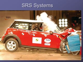
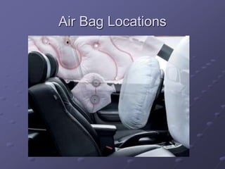
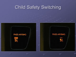
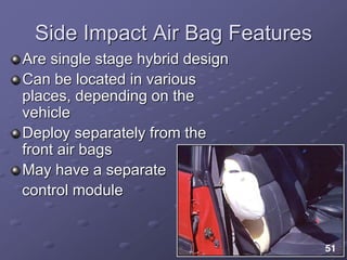
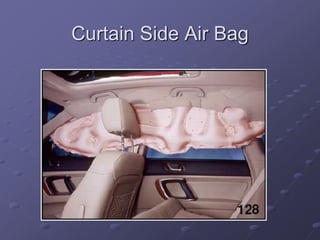
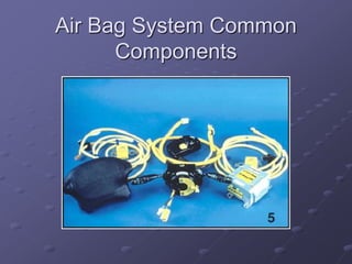
SRS Systems
BANG!!!
BANG!!!
Supplemental Restraint
Systems
Early studies found that a very high
percentage of drivers were not using seat
belts, resulting in ejection from vehicles
and severe trauma injuries
Passive (no driver action) restraints
developed in early 70’s and required by
law in late 80’s to protect vehicle
passengers when unbelted in vehicle
Supplemental Restraint
Systems
Passive Seat Belts
 Lap belts and shoulder belts
Air Bags
 Driver side and passenger side
 Early air bags 100% deployment power
 60/40 two stage as 100% too powerful in
some situations
 Both systems SUPPLEMENT Seat Belts
 Neither will work affectively without the seat
belts buckled
Passive Seat Belt System
Features
Uses a control module to monitor
operation
The module receives input from various
position and limit switches
The module activates a motor to
position the seat belt properly on the
driver’s shoulder
Passive/Automatic Seat Belt
Can be motor driven
and move from A
pillar to B pillar
Can be connected to
door (obsolete)
Passive Seat Belt
Motor & Cable
Popular in 80’s and 90’s
Motor located behind B
Pillar
Track runs from A to B
Pillar
Limit Switches located
in Both A and B Pillar
Tend to wear from dirt in
track, stopping belt in
mid-travel
Seat Belt Pretensioners
Used to tighten the
seat belt and shoulder
harness around the
occupant when the air
bag is deployed
May be mounted on
the buckle side or
retractor side of the
seat belt
Air Bag Safety
ALWAYS FOLLOW MFG TESTING
PROCEDURES!
CARRY AIR BAG ASSEMBLIES
FACE DOWN
ALWAYS DISARM SRS SYS PER
MFG BEFORE SERVICING
RELATED SYSTEMS
NEVER TAP INTO YELLOW WIRE
LOOMS
Air Bag Physics
Air bags deploy at about 200mph
Must stop a person moving 90
ft/sec in about 5 feet…without
killing the person!
LOUD!!!
 Jet engine @ 100’, gunshot 140dB
 Air bag deployment 165dB
 Death of hearing tissue 180dB
Want more physics?
Stand-by for more
pain…
Air Bag Locations
Driver (steering wheel) and passenger
front (dash)
Side air bag (side of seat)
Side-torso
Side tubular or curtain (above head)
Rear curtain
Center
Knee
Seat belt
Air Bag Locations
Motorcycle SRS Systems
Personal SRS Systems
Aviation SRS Systems
Runway safety for top fashion
models (can’t be too careful in
front of all those cameras…)
Available in Blonde, Brunette & Redhead
…or when you absolutely,
positively have to be at another
planet in one piece!
Pedestrian SRS Systems
Used to prevent
pedestrian head injury
In production now in
Asian markets
Was to be in US in
2012
REMEMBER..
Disarm air bags before servicing related parts!
 May need to wait up to 10 minutes for capacitors to
discharge
You must use torque wrench to torque sensors
and modules. A loose sensor can give false
acceleration readings.
Do NOT use air tools near sensors!
Live air bags must be deployed before sending
back. Don’t share the love.
Driver’s side Air Bag
Multi-Stage Air Bag Features
Uses two squibs to control the rate of
inflation
In a minor accident, only one squib is
deployed
As the severity of deceleration forces
increases, the second squib will deploy
60/40 Air Bag Inflator
In medium speed deceleration, 60%
charge is used
In high speed deceleration, both 60% and
40% charges are
used for full
occupant protection
Two Stage SRS connectors
Passenger Side Air Bag
Features
They are much larger than driver’s side
bags
They deploy with the driver’s side bag,
on most systems
Many systems have cut-off switches
 Usually on trucks where there is no back
seat
 Was add-on kit from Ford in the late 90’s
 Most new vehicles now equipped w/switch
Passenger Side Air Bag
Child Safety Switching
Side Impact Air Bag Features
Are single stage hybrid design
Can be located in various
places, depending on the
vehicle
Deploy separately from the
front air bags
May have a separate
control module
Curtain Side Air Bag
Air Bag System Common
Components
Air Bag System Common
Components
Diagnostic Module
 Constantly monitors the readiness of the
SRS electrical system
Crash Sensors
 Used to signal that the vehicle is involved
in a crash
Seat Weight/Position Sensors
 Inform module of passenger position &
weight
Diagnostic Module Functions
Controls the instrument panel warning
lamp
Continuously monitors all air bag
components
Controls air bag diagnostic functions
Provides an energy reserve to deploy air
bag if battery voltage is lost during a
collision
SRS Module
Note Arrow shows
mount direction
Diagnostic Module Self Test
When key is turned on the SRS module
performs the following checks
 Checks reserve power from capacitor
 Checks bulb condition
 Checks crash sensors for shorts opens or
grounds
 Checks air bag resistance
 If all checks are okay, the system is active
 Stores crash information for retrieval later
Very controversial!
Types of Sensors
Mass-type sensor
 Contains gold-plated contacts and a gold-
plated ball
Cash value 2 cents
 When vehicle is involved in a crash, the
ball rolls forward and closes the switch
contacts
Accelerometer sensor
 Contains a piezoelectric element that is
distorted in a crash
 Generates an analog voltage in relation to
the severity of the crash
Side Impact Sensor
Mounted in “B” pillar between front and
rear seat rows
Senses side impact, begins process of
inflating seat and curtain air bags
Seat Weight Sensor
OPDS Side Impact Air Bag
Air Bag On/Off Switches
May be manually controlled when a
child is sitting in the passenger seat
Some systems automatically detect
when a child seat is in the passenger
side of the front seat
 Sensors must be calibrated when any
portion of the seat is replaced.
 Accident may cause floor pan damage
making re-calibration necessary
Calibrating with Special Service
Tool: Plastic Butt
Typical Air Bag Deployment
Sequence
When a crash occurs, the arming sensor
will close first, then the crash sensors will
close
 The arming sensor must “set” first
 Then crash sensors tell SRS module
location/severity of crash
Typical Air Bag Deployment
Sequence
Within 40 milliseconds, the igniter module
burns the propellant and inflates the bag
Within 100 milliseconds, the air bag starts
to deflate
Within 2 seconds, the air bag is completely
deflated
By-Products of Inflator Module
Combustion
Nitrogen - 99.2%
Water - 0.6%
Hydrogen - 0.1%
Sodium oxide - less than 1/10 of 1 part per
million (PPM)
Sodium hydroxide - very minute quantity
Nothing that will make you sick if you touch
it…besides it just saved your life!
End SRS Systems

SRS systems

  • 1.
  • 3.
  • 5.
    Supplemental Restraint Systems Early studiesfound that a very high percentage of drivers were not using seat belts, resulting in ejection from vehicles and severe trauma injuries Passive (no driver action) restraints developed in early 70’s and required by law in late 80’s to protect vehicle passengers when unbelted in vehicle
  • 6.
    Supplemental Restraint Systems Passive SeatBelts  Lap belts and shoulder belts Air Bags  Driver side and passenger side  Early air bags 100% deployment power  60/40 two stage as 100% too powerful in some situations  Both systems SUPPLEMENT Seat Belts  Neither will work affectively without the seat belts buckled
  • 7.
    Passive Seat BeltSystem Features Uses a control module to monitor operation The module receives input from various position and limit switches The module activates a motor to position the seat belt properly on the driver’s shoulder
  • 8.
    Passive/Automatic Seat Belt Canbe motor driven and move from A pillar to B pillar Can be connected to door (obsolete)
  • 9.
    Passive Seat Belt Motor& Cable Popular in 80’s and 90’s Motor located behind B Pillar Track runs from A to B Pillar Limit Switches located in Both A and B Pillar Tend to wear from dirt in track, stopping belt in mid-travel
  • 10.
    Seat Belt Pretensioners Usedto tighten the seat belt and shoulder harness around the occupant when the air bag is deployed May be mounted on the buckle side or retractor side of the seat belt
  • 11.
    Air Bag Safety ALWAYSFOLLOW MFG TESTING PROCEDURES! CARRY AIR BAG ASSEMBLIES FACE DOWN ALWAYS DISARM SRS SYS PER MFG BEFORE SERVICING RELATED SYSTEMS NEVER TAP INTO YELLOW WIRE LOOMS
  • 12.
    Air Bag Physics Airbags deploy at about 200mph Must stop a person moving 90 ft/sec in about 5 feet…without killing the person! LOUD!!!  Jet engine @ 100’, gunshot 140dB  Air bag deployment 165dB  Death of hearing tissue 180dB
  • 13.
  • 15.
    Air Bag Locations Driver(steering wheel) and passenger front (dash) Side air bag (side of seat) Side-torso Side tubular or curtain (above head) Rear curtain Center Knee Seat belt
  • 16.
  • 17.
  • 18.
  • 19.
  • 20.
    Runway safety fortop fashion models (can’t be too careful in front of all those cameras…) Available in Blonde, Brunette & Redhead
  • 21.
    …or when youabsolutely, positively have to be at another planet in one piece!
  • 22.
    Pedestrian SRS Systems Usedto prevent pedestrian head injury In production now in Asian markets Was to be in US in 2012
  • 23.
    REMEMBER.. Disarm air bagsbefore servicing related parts!  May need to wait up to 10 minutes for capacitors to discharge You must use torque wrench to torque sensors and modules. A loose sensor can give false acceleration readings. Do NOT use air tools near sensors! Live air bags must be deployed before sending back. Don’t share the love.
  • 24.
  • 25.
    Multi-Stage Air BagFeatures Uses two squibs to control the rate of inflation In a minor accident, only one squib is deployed As the severity of deceleration forces increases, the second squib will deploy
  • 26.
    60/40 Air BagInflator In medium speed deceleration, 60% charge is used In high speed deceleration, both 60% and 40% charges are used for full occupant protection
  • 27.
    Two Stage SRSconnectors
  • 28.
    Passenger Side AirBag Features They are much larger than driver’s side bags They deploy with the driver’s side bag, on most systems Many systems have cut-off switches  Usually on trucks where there is no back seat  Was add-on kit from Ford in the late 90’s  Most new vehicles now equipped w/switch
  • 29.
  • 30.
  • 31.
    Side Impact AirBag Features Are single stage hybrid design Can be located in various places, depending on the vehicle Deploy separately from the front air bags May have a separate control module
  • 32.
  • 33.
    Air Bag SystemCommon Components
  • 34.
    Air Bag SystemCommon Components Diagnostic Module  Constantly monitors the readiness of the SRS electrical system Crash Sensors  Used to signal that the vehicle is involved in a crash Seat Weight/Position Sensors  Inform module of passenger position & weight
  • 35.
    Diagnostic Module Functions Controlsthe instrument panel warning lamp Continuously monitors all air bag components Controls air bag diagnostic functions Provides an energy reserve to deploy air bag if battery voltage is lost during a collision
  • 36.
    SRS Module Note Arrowshows mount direction
  • 37.
    Diagnostic Module SelfTest When key is turned on the SRS module performs the following checks  Checks reserve power from capacitor  Checks bulb condition  Checks crash sensors for shorts opens or grounds  Checks air bag resistance  If all checks are okay, the system is active  Stores crash information for retrieval later Very controversial!
  • 38.
    Types of Sensors Mass-typesensor  Contains gold-plated contacts and a gold- plated ball Cash value 2 cents  When vehicle is involved in a crash, the ball rolls forward and closes the switch contacts
  • 40.
    Accelerometer sensor  Containsa piezoelectric element that is distorted in a crash  Generates an analog voltage in relation to the severity of the crash
  • 41.
    Side Impact Sensor Mountedin “B” pillar between front and rear seat rows Senses side impact, begins process of inflating seat and curtain air bags
  • 42.
  • 43.
  • 44.
    Air Bag On/OffSwitches May be manually controlled when a child is sitting in the passenger seat Some systems automatically detect when a child seat is in the passenger side of the front seat  Sensors must be calibrated when any portion of the seat is replaced.  Accident may cause floor pan damage making re-calibration necessary
  • 45.
    Calibrating with SpecialService Tool: Plastic Butt
  • 46.
    Typical Air BagDeployment Sequence When a crash occurs, the arming sensor will close first, then the crash sensors will close  The arming sensor must “set” first  Then crash sensors tell SRS module location/severity of crash
  • 47.
    Typical Air BagDeployment Sequence Within 40 milliseconds, the igniter module burns the propellant and inflates the bag Within 100 milliseconds, the air bag starts to deflate Within 2 seconds, the air bag is completely deflated
  • 48.
    By-Products of InflatorModule Combustion Nitrogen - 99.2% Water - 0.6% Hydrogen - 0.1% Sodium oxide - less than 1/10 of 1 part per million (PPM) Sodium hydroxide - very minute quantity Nothing that will make you sick if you touch it…besides it just saved your life!
  • 49.