Downloaded 2,528 times

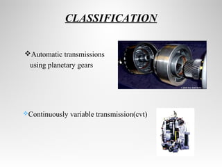
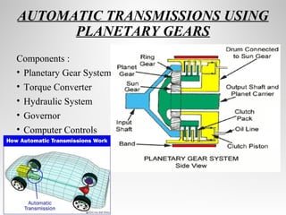
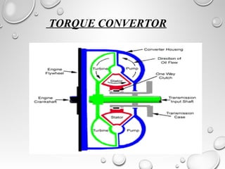
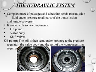
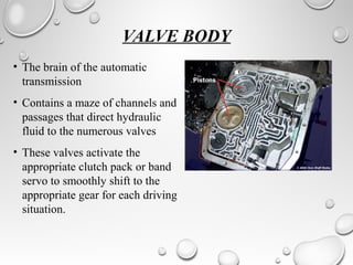
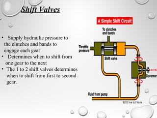
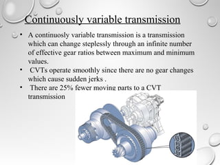


Automatic transmissions use either planetary gears or a continuously variable transmission (CVT) to automatically shift gears without clutch pedals. Planetary gear transmissions contain a planetary gear set, torque converter, hydraulic system, governor, and computer controls to shift smoothly. The hydraulic system includes an oil pump, valve body, and shift valves to direct fluid pressure and activate clutches during gear changes. A CVT provides stepless gear ratios between maximum and minimum values for smooth shifting without discernible gear changes. Modern automatic transmissions precisely control shifting using computer monitors of throttle, speed, load, and other factors.