Downloaded 1,782 times
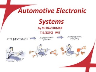
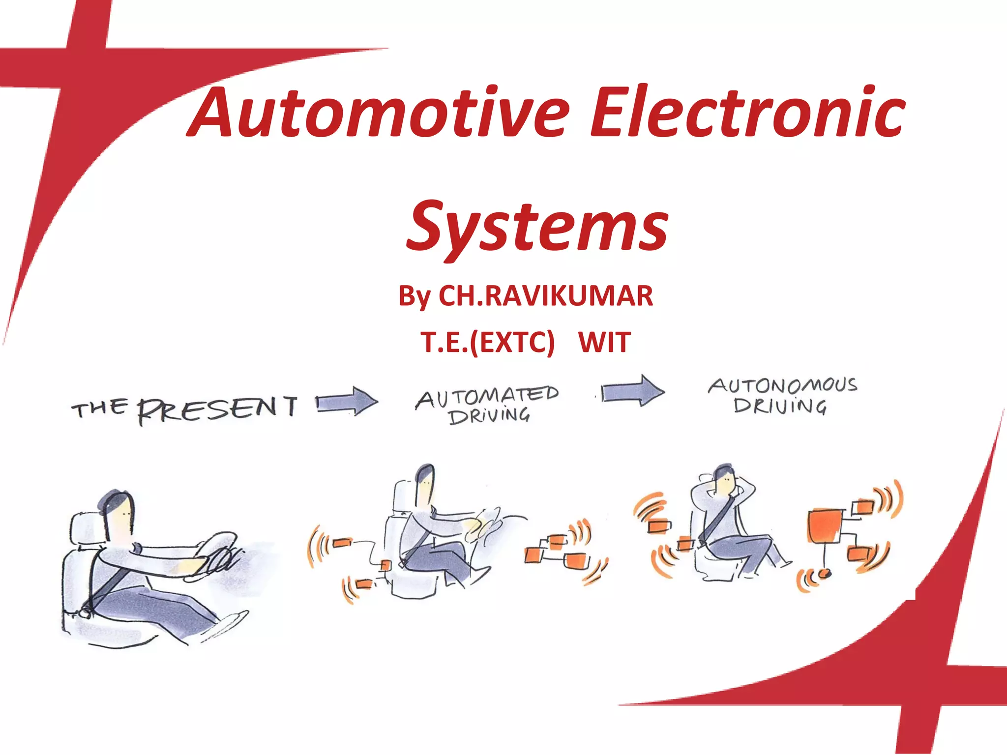
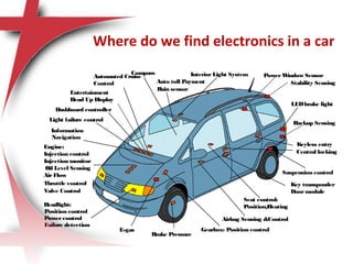
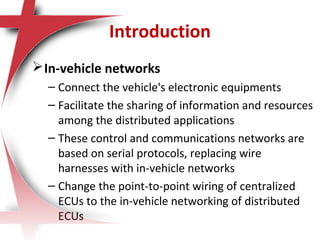
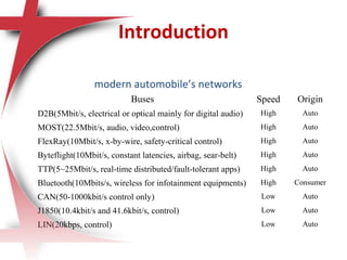
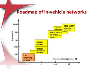
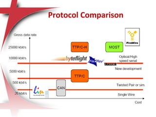
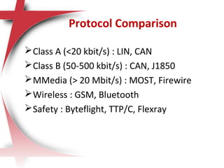
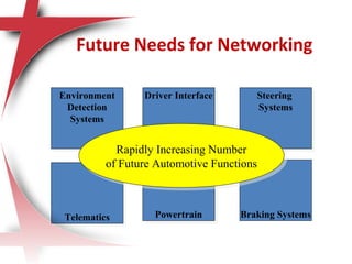
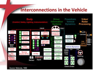
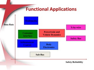
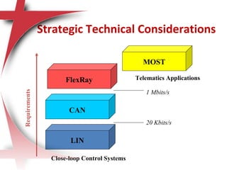
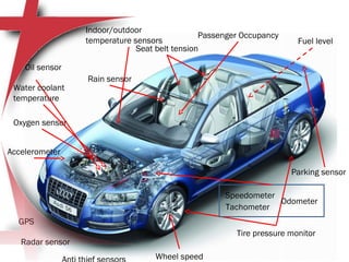
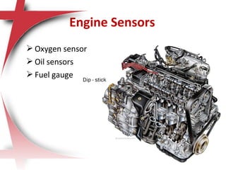
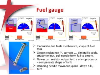
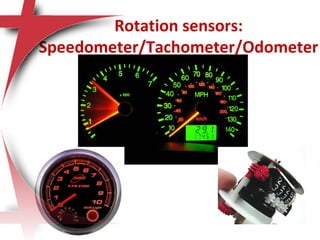
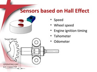
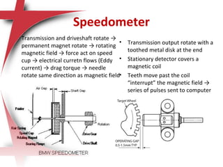
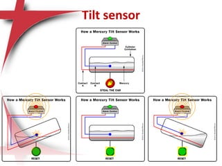
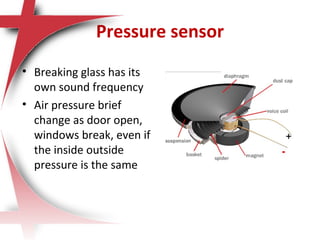
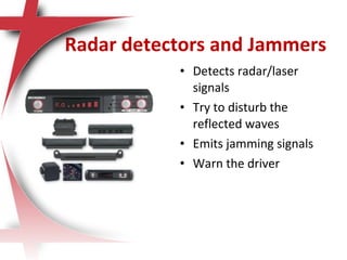


This document discusses automotive electronic systems and the various sensors used in modern vehicles. It begins by outlining several disciplines in automotive engineering such as safety, fuel economy, vehicle dynamics, and vehicle electronics. It then provides more details on specific sensors used for functions like engine monitoring, driver information, safety, and vehicle control. These include oxygen, oil, fuel level, speed, and temperature sensors. The document also discusses emerging in-vehicle networks used to connect electronic components and the various protocols used, including CAN, LIN, FlexRay, and MOST. It outlines the need for advanced sensor technologies and networking to enable more autonomous vehicle features in the future.


