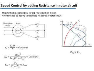
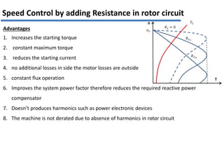
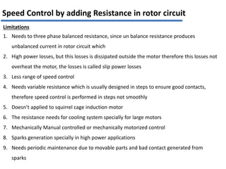
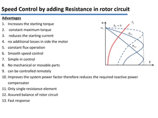
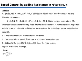
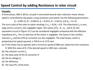
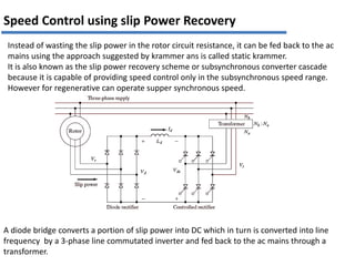
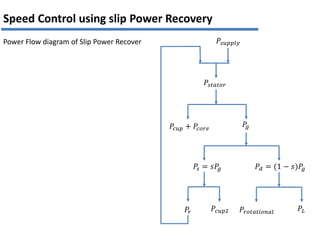
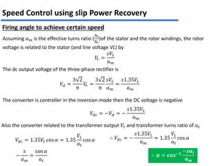
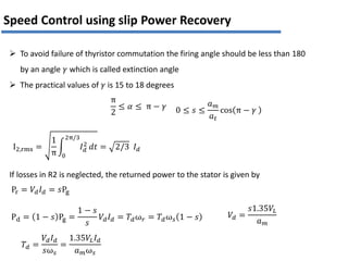
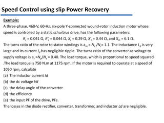
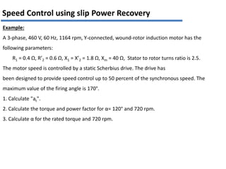
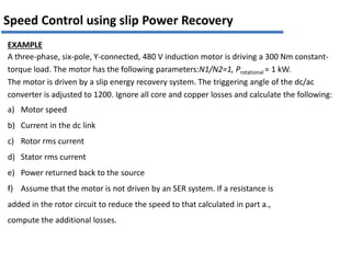
Advanced Electric Drives
Ass. Prof. Dr. Mohamed El-Kourfouly
Dr. Magdi A. Mosa
Electrical Power and Machine Department
Faculty of Engineering – Helwan University
Speed Control of 3phase I. M.
The speed and the torque of I.M can be varied by one of the following means:
1. Stator Voltage Control
2. Stator Frequency Control
3. Stator Voltage /Frequency Control
4. Rotor resistance control.
5. Slip Power Recovery
6. Rotor Voltage Control
7. Stator Current Control
8. Stator Current, and Frequency Control
9. Pole changing
T
n
𝑅𝑥1
𝑅𝑥 = 0
𝑅𝑥2
𝑛𝑠
𝑇𝐿
𝑅𝑥2
> 𝑅𝑥1
𝑇𝑚 =
3𝑉𝑝ℎ
2
2ω𝑠 𝑋1 + 𝑋′2
2 = 𝐶𝑜𝑠𝑛𝑡𝑎𝑛𝑡
𝑛𝑠 =
120𝑓
𝑃
= 𝐶𝑜𝑛𝑠𝑡𝑎𝑛𝑡
𝑆𝑐𝑟 =
𝑅′2
𝑋1 + 𝑋′2
∝ 𝑅𝑎𝑑𝑑
Speed Control by adding Resistance in rotor circuit
This method is applied only for slip ring induction motors
Accomplished by adding three phase resistance in rotor circuit
Advantages
1. Increases the starting torque
2. constant maximum torque
3. reduces the starting current
4. no additional losses in side the motor losses are outside
5. constant flux operation
6. Improves the system power factor therefore reduces the required reactive power
compensator
7. Doesn’t produces harmonics such as power electronic devices
8. The machine is not derated due to absence of harmonics in rotor circuit
Speed Control by adding Resistance in rotor circuit
T
n
𝑅𝑥1
𝑅𝑥 = 0
𝑅𝑥2
𝑛𝑠
𝑇𝐿
Limitations
1. Needs to three phase balanced resistance, since un balance resistance produces
unbalanced current in rotor circuit which
2. High power losses, but this losses is dissipated outside the motor therefore this losses not
overheat the motor, the losses is called slip power losses
3. Less range of speed control
4. Needs variable resistance which is usually designed in steps to ensure good contacts,
therefore speed control is performed in steps not smoothly
5. Doesn’t applied to squirrel cage induction motor
6. The resistance needs for cooling system specially for large motors
7. Mechanically Manual controlled or mechanically motorized control
8. Sparks generation specially in high power applications
9. Needs periodic maintenance due to movable parts and bad contact generated from
sparks
Speed Control by adding Resistance in rotor circuit
Id
Id
iR
Id
Ts
Ton
is
t
t
t
Id
The three-phase resistor may be replaced by a three-phase diode rectifier and a dc converter,
as shown in Figure, where the gate-turn-off thyristor (GTO) or an insulated-gate bipolar
transistor (IGBT) operates as switch.
1. The slip frequency AC rotor voltages are converted into DC by a 3-phase diode bridge and
applied across an enteral resistance R. The semiconductor switch is operated periodically
with a period T𝑠 and remains on for an interval ton in each period.
2. The effective value of resistance R changes from R to 0 as ton changes from 0 to T𝑠
3. The filter inductor L𝑑, is provided to minimize the ripple in current Id
iR
is
i2
i2
Id
2π/3 ωt
2π/3
2π
π
Id
Rotor Current
Is =
𝑡𝑜𝑛
𝑇𝑠
𝐼𝑑 = 𝐷𝐼𝑑
IR =
𝑡𝑜𝑓𝑓
𝑇𝑠
𝐼𝑑 = 1 − 𝐷 𝐼𝑑
𝐸𝑅 = 𝐼𝑑
2
R𝑡𝑜𝑓𝑓 = 𝐼𝑑
2
R 1 − D T
𝑃𝑅 =
𝐸𝑅
𝑇
=
𝐼𝑑
2
R 1 − D T
𝑇
= 𝐼𝑑
2
R 1 − D = 𝐼𝑑
2
𝑅𝑒𝑓𝑓
𝑹𝒆𝒇𝒇 = 𝐑 𝟏 − 𝑫
𝑡𝑜𝑓𝑓 = 1 − D 𝑇𝑠
𝑡𝑜𝑛 = D𝑇𝑠
The average value of switch current
The average value of Resistor current
Energy Dissipated in the resistance
Average power in the resistance
The effective value of the resistance
Id
Id
Id
Ts
ton
iR
is
t
t
t
Speed Control by adding Resistance in rotor circuit
Note
The effective value of the resistance is proportional inversely with the duty cycle D.
𝑅𝑒𝑓𝑓 = R 1 − D
If the switch is completely open during the switching periods
D = 0 𝑅𝑒𝑓𝑓 = R
If the switch is completely close during the switching periods
D = 1 𝑅𝑒𝑓𝑓 = 0
The effective value of the resistance is changed smoothly by varying
the duty ratio from 1 to 0
T
n
𝐷1 = 1
𝑛𝑠
𝑇𝐿
𝐷2
𝐷3
𝐷3 < 𝐷2 < 𝐷1
Speed Control by adding Resistance in rotor circuit
i2
Id
2π/3 ωt
2π/3
2π
π
Id
I2,rms =
1
π
𝐼𝑑
2
2π/3
0
𝑑𝑡 = 2/3 𝐼𝑑
𝑃𝑅 = 𝐼𝑑
2
R 1 − D =3𝐼2,𝑟𝑚𝑠
2
𝑅𝑎𝑐 = 3
2
3
𝐼𝑑
2
𝑅𝑎𝑐
𝑅𝑎𝑐 = 0.5 1 − D R
The effective AC resistance seen by rotor circuit
Speed Control by adding Resistance in rotor circuit
The total resistance in rotor circuit is the summation of 𝑅𝑎𝑐 and rotor windings resistance per
phase
𝑅𝑡𝑜𝑡𝑎𝑙 = 𝑅𝑎𝑐 + 𝑅2
the torque is produced only by the fundamental. The harmonics produce only
pulsating torques.
i2
Id
2π/3 ωt
2π/3
2π
π
Id
Fourier analysis
The waveform is quarter odd
Therefore even harmonics is zero
Average value is zero
The fundamental component is given by
𝑏1 =
4
π
𝐼𝑑 sin ω𝑡 𝑑ω𝑡 =
π/2
π/6
−
4
π
𝐼𝑑 cos
π
2
− cos
π
6
=
2 3
π
𝐼𝑑
𝐼𝑟1 =
𝑎1
2
=
6
π
𝐼𝑑 =
6
π
3
2
I2,rms =
3
π
I2,rms
This means the motor developed torque due to 𝐼𝑟1 while heat is generated is I2,rms therefore
for maximum current I2,rms the machine useful current is 𝐼𝑟1 the difference between this
values is called machine derating factor due to harmonics
Motor current derating =
𝐼𝑟1
I2,rms
=
3
π
= 0.95
Speed Control by adding Resistance in rotor circuit
If the ripple in the Id, commutation overlap in the diode bridge, skin effect, and –the reduction
in full-load speed due to losses in diode bridge, inverter, transformer, and semiconductor
switch are considered, the derating of the motor will be much higher.
Motor equivalent circuit
𝑃
𝑔 = 𝑃𝑚 + 3𝐼𝑟𝑚𝑠
2 𝑅𝑡𝑜𝑡𝑎𝑙 = 𝑃𝑚 + 3
π
3
2
𝐼𝑟1
2
𝑅𝑡𝑜𝑡𝑎𝑙 = 𝑃𝑚 + 3
π2
9
𝐼𝑟1
2
𝑅𝑡𝑜𝑡𝑎𝑙
𝑃𝑔1 = 𝑃
𝑔 = 𝑃𝑚 + 3
π2
9
𝐼𝑟1
2
𝑅𝑡𝑜𝑡𝑎𝑙
The total power in rotor circuit is given by
The fundamental power in rotor circuit comes through air gap is given by
𝑃𝑚 = (1 − 𝑠)𝑃𝑔1 = (1 − 𝑠)𝑃𝑚 + 3
π2
9
𝐼𝑟1
2
𝑅𝑡𝑜𝑡𝑎𝑙(1 − 𝑠)
𝑃𝑚 = 3
π
3
2
𝐼𝑟1
2
𝑅𝑡𝑜𝑡𝑎𝑙
(1 − 𝑠)
𝑠
𝑃
𝑔 = 𝑃𝑚 + 3
π2
9
𝐼𝑟1
2
𝑅𝑡𝑜𝑡𝑎𝑙 = 3
π2
9
𝐼𝑟1
2
𝑅𝑡𝑜𝑡𝑎𝑙
(1 − 𝑠)
𝑠
+ 3
π2
9
𝐼𝑟1
2
𝑅𝑡𝑜𝑡𝑎𝑙
𝑃
𝑔 = 3𝐼𝑟1
2
π2
9
− 1 𝑅𝑡𝑜𝑡𝑎𝑙 +
𝑅𝑡𝑜𝑡𝑎𝑙
𝑠
= 3𝐼𝑟1
2
𝑅𝑒
Speed Control by adding Resistance in rotor circuit
The effective rotor resistance
𝑅𝑒 =
π2
9
− 1 𝑅𝑡𝑜𝑡𝑎𝑙 +
𝑅𝑡𝑜𝑡𝑎𝑙
𝑠
= 𝑅ℎ +
𝑅𝑓
𝑠
𝑅ℎ =
π2
9
− 1 𝑅𝑡𝑜𝑡𝑎𝑙 =
π2
9
− 1 0.5 1 − D 𝑅 + 𝑅2
𝑅𝑓 = 𝑅𝑡𝑜𝑡𝑎𝑙 = 0.5 1 − D 𝑅 + 𝑅2
𝑅ℎis the resistance equivalent to harmonic losses
𝑅𝑓is the resistance corresponding to fundamental components losses
Speed Control by adding Resistance in rotor circuit
DC-Coil
1. The filter inductor L, is provided to minimize the ripple in current Id‘. A high ripple in Id
produces high harmonic content in the rotor, increasing copper losses and causing
derating of the motor.
2. The filter inductor also helps in eliminating discontinuous conduction at light loads.
3. As in the case of a DC motor, discontinuous conduction makes the speed regulation poor.
4. The main contributor to the ripple is the diode bridge and not the semiconductor switch,
because it operates at a sufficiently high frequency.
Speed Control by adding Resistance in rotor circuit
Advantages
1. Increases the starting torque
2. constant maximum torque
3. reduces the starting current
4. no additional losses in side the motor
5. constant flux operation
6. Smooth speed control
7. Simple in control
8. No mechanical or movable parts
9. can be controlled remotely
10. Improves the system power factor therefore reduces the required reactive power
compensator
11. Only single resistance element
12. Assured balance of rotor circuit
13. Fast response
Speed Control by adding Resistance in rotor circuit
T
n
𝑅𝑥1
𝑅𝑥 = 0
𝑅𝑥2
𝑛𝑠
𝑇𝐿
Limitations
1. High power losses, but this losses is dissipated outside the motor therefore this losses not
overheat the motor, the losses is called slip power losses
2. Less range of speed control
3. Doesn’t applied to squirrel cage induction motor
4. The resistance needs for cooling system specially for large motors
5. Produces harmonics in rotor circuit therefore the motor should be oversized or derated
6. Needs DC coil to avoid discontinues current operation specially at light loads
Speed Control by adding Resistance in rotor circuit
Example
A 3-phase, 460 V, 60 Hz, 1164 rpm, Y-connected, wound-rotor induction motor has the
following parameters:
R1 = 0.4 Ω, R’2 = 0.6 Ω, X1 = X’2 = 1.8 Ω, Xm = 40 Ω, Stator to rotor turns ratio is 2.5.
The motor speed is controlled by static rotor resistance control. Fi1ter resistance is neglected
and the external resistance is chosen such that at D=0, the breakdown torque is obtained at
standstill.
1. Ca1cu1ate the va1ue of the external resistance.
2. Ca1culate D for a speed of 960 rpm at 1.5 times the rated torque.
3. Ca1culate the speed for D=0.6 and l.5 times the rated torque.
Neglect friction and windage.
Speed Control by adding Resistance in rotor circuit
Note:
R’=
𝑁𝑠
𝑁𝑟
2
R
Example:
A three-phase, 460-V, 60-Hz, six-pole Y-connected wound-rotor induction motor whose
speed is controlled by slip power, using resistance and switch, has the following parameters:
Rs = 0.041 Ω, R’r = 0.044 Ω, Xs = 0.29 Ω, X’r = 0.44 Ω, and Xm = 6.1 Ω.
The turns ratio of the rotor to stator windings is nm = Nr/Ns = 0.9. The inductance Ld is very
large and its current Id has negligible ripple. The values of Rs , Rr , Xs , and Xr for the
equivalent circuit in Figure 15.2 can be considered negligible compared with the effective
impedance of Ld. The no-load loss of the motor is negligible. The losses in the rectifier,
inductor Ld, and the GTO dc converter are also negligible. The load torque, which is
proportional to speed squared, is 750 N.m at 1175 rpm.
(a) If the motor has to operate with a minimum speed of 800 rpm, determine the resistance
R. With this value of R, if the desired speed is 1050 rpm, calculate
(b) the inductor current Id
(c) the duty cycle of the dc converter D
(d) the dc voltage Vd
(e) the efficiency
(f) the input PFs of the drive.
Speed Control by adding Resistance in rotor circuit
Instead of wasting the slip power in the rotor circuit resistance, it can be fed back to the ac
mains using the approach suggested by krammer ans is called static krammer.
It is also known as the slip power recovery scheme or subsynchronous converter cascade
because it is capable of providing speed control only in the subsynchronous speed range.
However for regenerative can operate supper synchronous speed.
A diode bridge converts a portion of slip power into DC which in turn is converted into line
frequency by a 3-phase line commutated inverter and fed back to the ac mains through a
transformer.
Speed Control using slip Power Recovery
𝑃𝑠𝑢𝑝𝑝𝑙𝑦
𝑃𝑠𝑡𝑎𝑡𝑜𝑟
𝑃𝑐𝑢𝑝 + 𝑃𝑐𝑜𝑟𝑒
𝑃
𝑔
𝑃𝑑 = (1 − 𝑠)𝑃
𝑔
𝑃𝑠 = 𝑠𝑃
𝑔
𝑃𝐿
𝑃𝑐𝑢𝑝2 𝑃𝑟𝑜𝑡𝑎𝑡𝑖𝑜𝑛𝑎𝑙
𝑃𝑟
Speed Control using slip Power Recovery
Power Flow diagram of Slip Power Recover
Assuming 𝑎𝑚 is the effective turns ratio (
𝑁𝑠
𝑁𝑟
)of the stator and the rotor windings, the rotor
voltage is related to the stator (and line voltage VL) by
𝑉
𝑟 =
𝑠𝑉𝐿
𝑎𝑚
The dc output voltage of the three-phase rectifier is
𝑉𝑑 =
3 2
π
𝑉
𝑟 =
3 2
π
𝑠𝑉𝐿
𝑎𝑚
=
𝑠1.35𝑉𝐿
𝑎𝑚
The converter is controller in the inversion mode then the DC voltage is negative
𝑉𝑑𝑐 = −𝑉𝑑 = −
𝑠1.35𝑉𝐿
𝑎𝑚
Also the converter related to the transformer output 𝑉𝑡 and transformer turns ratio of 𝑎𝑡
𝑉𝑑𝑐 = 1.35𝑉𝑡 cos 𝛼 = 1.35
𝑉𝐿
𝑎𝑡
cos 𝛼 ∴ 𝑉𝑑𝑐 = −
𝑠1.35𝑉𝐿
𝑎𝑚
= 1.35
𝑉𝐿
𝑎𝑡
cos 𝛼
−
𝑠
𝑎𝑚
=
cos 𝛼
𝑎𝑡
∴ 𝜶 = 𝒄𝒐𝒔−𝟏
−𝒔𝒂𝒕
𝒂𝒎
Speed Control using slip Power Recovery
Firing angle to achieve certain speed
I2,rms =
1
π
𝐼𝑑
2
2π/3
0
𝑑𝑡 = 2/3 𝐼𝑑
π
2
≤ 𝛼 ≤ π − 𝛾 0 ≤ 𝑠 ≤
𝑎𝑚
𝑎𝑡
cos π − 𝛾
Speed Control using slip Power Recovery
Pr = 𝑉𝑑𝐼𝑑 = 𝑠Pg
If losses in R2 is neglected, the returned power to the stator is given by
Pd = 1 − 𝑠 Pg =
1 − 𝑠
𝑠
𝑉𝑑𝐼𝑑 = 𝑇𝑑ω𝑟 = 𝑇𝑑ω𝑠 1 − 𝑠
𝑇𝑑 =
𝑉𝑑𝐼𝑑
𝑠ω𝑠
=
1.35𝑉𝐿𝐼𝑑
𝑎𝑚ω𝑠
𝑉𝑑 =
𝑠1.35𝑉𝐿
𝑎𝑚
 To avoid failure of thyristor commutation the firing angle should be less than 180
by an angle 𝛾 which is called extinction angle
 The practical values of 𝛾 is 15 to 18 degrees
Example:
A three-phase, 460-V, 60-Hz, six-pole Y-connected wound-rotor induction motor whose
speed is controlled by a static schurbius drive, has the following parameters:
Rs = 0.041 Ω, R’r = 0.044 Ω, Xs = 0.29 Ω, X’r = 0.44 Ω, and Xm = 6.1 Ω.
The turns ratio of the rotor to stator windings is am = Ns /Nr= 1.1. The inductance Ld is very
large and its current Id has negligible ripple. The turns ratio of the converter ac voltage to
supply voltage is at =Np/Ns = 0.40. The load torque, which is proportional to speed squared
.The load torque is 750 N.m at 1175 rpm. If the motor is required to operate at a speed of
1050 rpm, calculate
(a) The inductor current Id
(b) the dc voltage Vd
(c) the delay angle of the converter
(d) the efficiency
(e) the input PF of the drive, PFs.
The losses in the diode rectifier, converter, transformer, and inductor Ld are negligible.
Speed Control using slip Power Recovery
Example:
A 3-phase, 460 V, 60 Hz, 1164 rpm, Y-connected, wound-rotor induction motor has the
following parameters:
R1 = 0.4 Ω, R’2 = 0.6 Ω, X1 = X’2 = 1.8 Ω, Xm = 40 Ω, Stator to rotor turns ratio is 2.5.
The motor speed is controlled by a static Scherbius drive. The drive has
been designed to provide speed control up to 50 percent of the synchronous speed. The
maximum value of the firing angle is 170°.
1. Calculate "at".
2. Calculate the torque and power factor for α= 120° and 720 rpm.
3. Calculate α for the rated torque and 720 rpm.
EXAMPLE
A three-phase, six-pole, Y-connected, 480 V induction motor is driving a 300 Nm constant-
torque load. The motor has the following parameters:N1/N2=1, Protational = 1 kW.
The motor is driven by a slip energy recovery system. The triggering angle of the dc/ac
converter is adjusted to 1200. Ignore all core and copper losses and calculate the following:
a) Motor speed
b) Current in the dc link
c) Rotor rms current
d) Stator rms current
e) Power returned back to the source
f) Assume that the motor is not driven by an SER system. If a resistance is
added in the rotor circuit to reduce the speed to that calculated in part a.,
compute the additional losses.
Speed Control using slip Power Recovery
Dr. Magdi A. Mosa
magdimosa@yahoo.com
01282969241

Drive_Lecture_4_slip_power (1) for machines

  • 1.
    Advanced Electric Drives Ass.Prof. Dr. Mohamed El-Kourfouly Dr. Magdi A. Mosa Electrical Power and Machine Department Faculty of Engineering – Helwan University
  • 2.
    Speed Control of3phase I. M. The speed and the torque of I.M can be varied by one of the following means: 1. Stator Voltage Control 2. Stator Frequency Control 3. Stator Voltage /Frequency Control 4. Rotor resistance control. 5. Slip Power Recovery 6. Rotor Voltage Control 7. Stator Current Control 8. Stator Current, and Frequency Control 9. Pole changing
  • 3.
    T n 𝑅𝑥1 𝑅𝑥 = 0 𝑅𝑥2 𝑛𝑠 𝑇𝐿 𝑅𝑥2 >𝑅𝑥1 𝑇𝑚 = 3𝑉𝑝ℎ 2 2ω𝑠 𝑋1 + 𝑋′2 2 = 𝐶𝑜𝑠𝑛𝑡𝑎𝑛𝑡 𝑛𝑠 = 120𝑓 𝑃 = 𝐶𝑜𝑛𝑠𝑡𝑎𝑛𝑡 𝑆𝑐𝑟 = 𝑅′2 𝑋1 + 𝑋′2 ∝ 𝑅𝑎𝑑𝑑 Speed Control by adding Resistance in rotor circuit This method is applied only for slip ring induction motors Accomplished by adding three phase resistance in rotor circuit
  • 4.
    Advantages 1. Increases thestarting torque 2. constant maximum torque 3. reduces the starting current 4. no additional losses in side the motor losses are outside 5. constant flux operation 6. Improves the system power factor therefore reduces the required reactive power compensator 7. Doesn’t produces harmonics such as power electronic devices 8. The machine is not derated due to absence of harmonics in rotor circuit Speed Control by adding Resistance in rotor circuit T n 𝑅𝑥1 𝑅𝑥 = 0 𝑅𝑥2 𝑛𝑠 𝑇𝐿
  • 5.
    Limitations 1. Needs tothree phase balanced resistance, since un balance resistance produces unbalanced current in rotor circuit which 2. High power losses, but this losses is dissipated outside the motor therefore this losses not overheat the motor, the losses is called slip power losses 3. Less range of speed control 4. Needs variable resistance which is usually designed in steps to ensure good contacts, therefore speed control is performed in steps not smoothly 5. Doesn’t applied to squirrel cage induction motor 6. The resistance needs for cooling system specially for large motors 7. Mechanically Manual controlled or mechanically motorized control 8. Sparks generation specially in high power applications 9. Needs periodic maintenance due to movable parts and bad contact generated from sparks Speed Control by adding Resistance in rotor circuit
  • 6.
    Speed Control byadding Resistance in rotor circuit Id Id iR Id Ts Ton is t t t Id The three-phase resistor may be replaced by a three-phase diode rectifier and a dc converter, as shown in Figure, where the gate-turn-off thyristor (GTO) or an insulated-gate bipolar transistor (IGBT) operates as switch. 1. The slip frequency AC rotor voltages are converted into DC by a 3-phase diode bridge and applied across an enteral resistance R. The semiconductor switch is operated periodically with a period T𝑠 and remains on for an interval ton in each period. 2. The effective value of resistance R changes from R to 0 as ton changes from 0 to T𝑠 3. The filter inductor L𝑑, is provided to minimize the ripple in current Id iR is i2 i2 Id 2π/3 ωt 2π/3 2π π Id Rotor Current
  • 7.
    Is = 𝑡𝑜𝑛 𝑇𝑠 𝐼𝑑 =𝐷𝐼𝑑 IR = 𝑡𝑜𝑓𝑓 𝑇𝑠 𝐼𝑑 = 1 − 𝐷 𝐼𝑑 𝐸𝑅 = 𝐼𝑑 2 R𝑡𝑜𝑓𝑓 = 𝐼𝑑 2 R 1 − D T 𝑃𝑅 = 𝐸𝑅 𝑇 = 𝐼𝑑 2 R 1 − D T 𝑇 = 𝐼𝑑 2 R 1 − D = 𝐼𝑑 2 𝑅𝑒𝑓𝑓 𝑹𝒆𝒇𝒇 = 𝐑 𝟏 − 𝑫 𝑡𝑜𝑓𝑓 = 1 − D 𝑇𝑠 𝑡𝑜𝑛 = D𝑇𝑠 The average value of switch current The average value of Resistor current Energy Dissipated in the resistance Average power in the resistance The effective value of the resistance Id Id Id Ts ton iR is t t t Speed Control by adding Resistance in rotor circuit
  • 8.
    Note The effective valueof the resistance is proportional inversely with the duty cycle D. 𝑅𝑒𝑓𝑓 = R 1 − D If the switch is completely open during the switching periods D = 0 𝑅𝑒𝑓𝑓 = R If the switch is completely close during the switching periods D = 1 𝑅𝑒𝑓𝑓 = 0 The effective value of the resistance is changed smoothly by varying the duty ratio from 1 to 0 T n 𝐷1 = 1 𝑛𝑠 𝑇𝐿 𝐷2 𝐷3 𝐷3 < 𝐷2 < 𝐷1 Speed Control by adding Resistance in rotor circuit i2 Id 2π/3 ωt 2π/3 2π π Id I2,rms = 1 π 𝐼𝑑 2 2π/3 0 𝑑𝑡 = 2/3 𝐼𝑑
  • 9.
    𝑃𝑅 = 𝐼𝑑 2 R1 − D =3𝐼2,𝑟𝑚𝑠 2 𝑅𝑎𝑐 = 3 2 3 𝐼𝑑 2 𝑅𝑎𝑐 𝑅𝑎𝑐 = 0.5 1 − D R The effective AC resistance seen by rotor circuit Speed Control by adding Resistance in rotor circuit The total resistance in rotor circuit is the summation of 𝑅𝑎𝑐 and rotor windings resistance per phase 𝑅𝑡𝑜𝑡𝑎𝑙 = 𝑅𝑎𝑐 + 𝑅2 the torque is produced only by the fundamental. The harmonics produce only pulsating torques. i2 Id 2π/3 ωt 2π/3 2π π Id Fourier analysis The waveform is quarter odd Therefore even harmonics is zero Average value is zero The fundamental component is given by
  • 10.
    𝑏1 = 4 π 𝐼𝑑 sinω𝑡 𝑑ω𝑡 = π/2 π/6 − 4 π 𝐼𝑑 cos π 2 − cos π 6 = 2 3 π 𝐼𝑑 𝐼𝑟1 = 𝑎1 2 = 6 π 𝐼𝑑 = 6 π 3 2 I2,rms = 3 π I2,rms This means the motor developed torque due to 𝐼𝑟1 while heat is generated is I2,rms therefore for maximum current I2,rms the machine useful current is 𝐼𝑟1 the difference between this values is called machine derating factor due to harmonics Motor current derating = 𝐼𝑟1 I2,rms = 3 π = 0.95 Speed Control by adding Resistance in rotor circuit If the ripple in the Id, commutation overlap in the diode bridge, skin effect, and –the reduction in full-load speed due to losses in diode bridge, inverter, transformer, and semiconductor switch are considered, the derating of the motor will be much higher.
  • 11.
    Motor equivalent circuit 𝑃 𝑔= 𝑃𝑚 + 3𝐼𝑟𝑚𝑠 2 𝑅𝑡𝑜𝑡𝑎𝑙 = 𝑃𝑚 + 3 π 3 2 𝐼𝑟1 2 𝑅𝑡𝑜𝑡𝑎𝑙 = 𝑃𝑚 + 3 π2 9 𝐼𝑟1 2 𝑅𝑡𝑜𝑡𝑎𝑙 𝑃𝑔1 = 𝑃 𝑔 = 𝑃𝑚 + 3 π2 9 𝐼𝑟1 2 𝑅𝑡𝑜𝑡𝑎𝑙 The total power in rotor circuit is given by The fundamental power in rotor circuit comes through air gap is given by 𝑃𝑚 = (1 − 𝑠)𝑃𝑔1 = (1 − 𝑠)𝑃𝑚 + 3 π2 9 𝐼𝑟1 2 𝑅𝑡𝑜𝑡𝑎𝑙(1 − 𝑠) 𝑃𝑚 = 3 π 3 2 𝐼𝑟1 2 𝑅𝑡𝑜𝑡𝑎𝑙 (1 − 𝑠) 𝑠 𝑃 𝑔 = 𝑃𝑚 + 3 π2 9 𝐼𝑟1 2 𝑅𝑡𝑜𝑡𝑎𝑙 = 3 π2 9 𝐼𝑟1 2 𝑅𝑡𝑜𝑡𝑎𝑙 (1 − 𝑠) 𝑠 + 3 π2 9 𝐼𝑟1 2 𝑅𝑡𝑜𝑡𝑎𝑙 𝑃 𝑔 = 3𝐼𝑟1 2 π2 9 − 1 𝑅𝑡𝑜𝑡𝑎𝑙 + 𝑅𝑡𝑜𝑡𝑎𝑙 𝑠 = 3𝐼𝑟1 2 𝑅𝑒 Speed Control by adding Resistance in rotor circuit
  • 12.
    The effective rotorresistance 𝑅𝑒 = π2 9 − 1 𝑅𝑡𝑜𝑡𝑎𝑙 + 𝑅𝑡𝑜𝑡𝑎𝑙 𝑠 = 𝑅ℎ + 𝑅𝑓 𝑠 𝑅ℎ = π2 9 − 1 𝑅𝑡𝑜𝑡𝑎𝑙 = π2 9 − 1 0.5 1 − D 𝑅 + 𝑅2 𝑅𝑓 = 𝑅𝑡𝑜𝑡𝑎𝑙 = 0.5 1 − D 𝑅 + 𝑅2 𝑅ℎis the resistance equivalent to harmonic losses 𝑅𝑓is the resistance corresponding to fundamental components losses Speed Control by adding Resistance in rotor circuit
  • 13.
    DC-Coil 1. The filterinductor L, is provided to minimize the ripple in current Id‘. A high ripple in Id produces high harmonic content in the rotor, increasing copper losses and causing derating of the motor. 2. The filter inductor also helps in eliminating discontinuous conduction at light loads. 3. As in the case of a DC motor, discontinuous conduction makes the speed regulation poor. 4. The main contributor to the ripple is the diode bridge and not the semiconductor switch, because it operates at a sufficiently high frequency. Speed Control by adding Resistance in rotor circuit
  • 14.
    Advantages 1. Increases thestarting torque 2. constant maximum torque 3. reduces the starting current 4. no additional losses in side the motor 5. constant flux operation 6. Smooth speed control 7. Simple in control 8. No mechanical or movable parts 9. can be controlled remotely 10. Improves the system power factor therefore reduces the required reactive power compensator 11. Only single resistance element 12. Assured balance of rotor circuit 13. Fast response Speed Control by adding Resistance in rotor circuit T n 𝑅𝑥1 𝑅𝑥 = 0 𝑅𝑥2 𝑛𝑠 𝑇𝐿
  • 15.
    Limitations 1. High powerlosses, but this losses is dissipated outside the motor therefore this losses not overheat the motor, the losses is called slip power losses 2. Less range of speed control 3. Doesn’t applied to squirrel cage induction motor 4. The resistance needs for cooling system specially for large motors 5. Produces harmonics in rotor circuit therefore the motor should be oversized or derated 6. Needs DC coil to avoid discontinues current operation specially at light loads Speed Control by adding Resistance in rotor circuit
  • 16.
    Example A 3-phase, 460V, 60 Hz, 1164 rpm, Y-connected, wound-rotor induction motor has the following parameters: R1 = 0.4 Ω, R’2 = 0.6 Ω, X1 = X’2 = 1.8 Ω, Xm = 40 Ω, Stator to rotor turns ratio is 2.5. The motor speed is controlled by static rotor resistance control. Fi1ter resistance is neglected and the external resistance is chosen such that at D=0, the breakdown torque is obtained at standstill. 1. Ca1cu1ate the va1ue of the external resistance. 2. Ca1culate D for a speed of 960 rpm at 1.5 times the rated torque. 3. Ca1culate the speed for D=0.6 and l.5 times the rated torque. Neglect friction and windage. Speed Control by adding Resistance in rotor circuit Note: R’= 𝑁𝑠 𝑁𝑟 2 R
  • 17.
    Example: A three-phase, 460-V,60-Hz, six-pole Y-connected wound-rotor induction motor whose speed is controlled by slip power, using resistance and switch, has the following parameters: Rs = 0.041 Ω, R’r = 0.044 Ω, Xs = 0.29 Ω, X’r = 0.44 Ω, and Xm = 6.1 Ω. The turns ratio of the rotor to stator windings is nm = Nr/Ns = 0.9. The inductance Ld is very large and its current Id has negligible ripple. The values of Rs , Rr , Xs , and Xr for the equivalent circuit in Figure 15.2 can be considered negligible compared with the effective impedance of Ld. The no-load loss of the motor is negligible. The losses in the rectifier, inductor Ld, and the GTO dc converter are also negligible. The load torque, which is proportional to speed squared, is 750 N.m at 1175 rpm. (a) If the motor has to operate with a minimum speed of 800 rpm, determine the resistance R. With this value of R, if the desired speed is 1050 rpm, calculate (b) the inductor current Id (c) the duty cycle of the dc converter D (d) the dc voltage Vd (e) the efficiency (f) the input PFs of the drive. Speed Control by adding Resistance in rotor circuit
  • 18.
    Instead of wastingthe slip power in the rotor circuit resistance, it can be fed back to the ac mains using the approach suggested by krammer ans is called static krammer. It is also known as the slip power recovery scheme or subsynchronous converter cascade because it is capable of providing speed control only in the subsynchronous speed range. However for regenerative can operate supper synchronous speed. A diode bridge converts a portion of slip power into DC which in turn is converted into line frequency by a 3-phase line commutated inverter and fed back to the ac mains through a transformer. Speed Control using slip Power Recovery
  • 19.
    𝑃𝑠𝑢𝑝𝑝𝑙𝑦 𝑃𝑠𝑡𝑎𝑡𝑜𝑟 𝑃𝑐𝑢𝑝 + 𝑃𝑐𝑜𝑟𝑒 𝑃 𝑔 𝑃𝑑= (1 − 𝑠)𝑃 𝑔 𝑃𝑠 = 𝑠𝑃 𝑔 𝑃𝐿 𝑃𝑐𝑢𝑝2 𝑃𝑟𝑜𝑡𝑎𝑡𝑖𝑜𝑛𝑎𝑙 𝑃𝑟 Speed Control using slip Power Recovery Power Flow diagram of Slip Power Recover
  • 20.
    Assuming 𝑎𝑚 isthe effective turns ratio ( 𝑁𝑠 𝑁𝑟 )of the stator and the rotor windings, the rotor voltage is related to the stator (and line voltage VL) by 𝑉 𝑟 = 𝑠𝑉𝐿 𝑎𝑚 The dc output voltage of the three-phase rectifier is 𝑉𝑑 = 3 2 π 𝑉 𝑟 = 3 2 π 𝑠𝑉𝐿 𝑎𝑚 = 𝑠1.35𝑉𝐿 𝑎𝑚 The converter is controller in the inversion mode then the DC voltage is negative 𝑉𝑑𝑐 = −𝑉𝑑 = − 𝑠1.35𝑉𝐿 𝑎𝑚 Also the converter related to the transformer output 𝑉𝑡 and transformer turns ratio of 𝑎𝑡 𝑉𝑑𝑐 = 1.35𝑉𝑡 cos 𝛼 = 1.35 𝑉𝐿 𝑎𝑡 cos 𝛼 ∴ 𝑉𝑑𝑐 = − 𝑠1.35𝑉𝐿 𝑎𝑚 = 1.35 𝑉𝐿 𝑎𝑡 cos 𝛼 − 𝑠 𝑎𝑚 = cos 𝛼 𝑎𝑡 ∴ 𝜶 = 𝒄𝒐𝒔−𝟏 −𝒔𝒂𝒕 𝒂𝒎 Speed Control using slip Power Recovery Firing angle to achieve certain speed
  • 21.
    I2,rms = 1 π 𝐼𝑑 2 2π/3 0 𝑑𝑡 =2/3 𝐼𝑑 π 2 ≤ 𝛼 ≤ π − 𝛾 0 ≤ 𝑠 ≤ 𝑎𝑚 𝑎𝑡 cos π − 𝛾 Speed Control using slip Power Recovery Pr = 𝑉𝑑𝐼𝑑 = 𝑠Pg If losses in R2 is neglected, the returned power to the stator is given by Pd = 1 − 𝑠 Pg = 1 − 𝑠 𝑠 𝑉𝑑𝐼𝑑 = 𝑇𝑑ω𝑟 = 𝑇𝑑ω𝑠 1 − 𝑠 𝑇𝑑 = 𝑉𝑑𝐼𝑑 𝑠ω𝑠 = 1.35𝑉𝐿𝐼𝑑 𝑎𝑚ω𝑠 𝑉𝑑 = 𝑠1.35𝑉𝐿 𝑎𝑚  To avoid failure of thyristor commutation the firing angle should be less than 180 by an angle 𝛾 which is called extinction angle  The practical values of 𝛾 is 15 to 18 degrees
  • 22.
    Example: A three-phase, 460-V,60-Hz, six-pole Y-connected wound-rotor induction motor whose speed is controlled by a static schurbius drive, has the following parameters: Rs = 0.041 Ω, R’r = 0.044 Ω, Xs = 0.29 Ω, X’r = 0.44 Ω, and Xm = 6.1 Ω. The turns ratio of the rotor to stator windings is am = Ns /Nr= 1.1. The inductance Ld is very large and its current Id has negligible ripple. The turns ratio of the converter ac voltage to supply voltage is at =Np/Ns = 0.40. The load torque, which is proportional to speed squared .The load torque is 750 N.m at 1175 rpm. If the motor is required to operate at a speed of 1050 rpm, calculate (a) The inductor current Id (b) the dc voltage Vd (c) the delay angle of the converter (d) the efficiency (e) the input PF of the drive, PFs. The losses in the diode rectifier, converter, transformer, and inductor Ld are negligible. Speed Control using slip Power Recovery
  • 23.
    Speed Control usingslip Power Recovery Example: A 3-phase, 460 V, 60 Hz, 1164 rpm, Y-connected, wound-rotor induction motor has the following parameters: R1 = 0.4 Ω, R’2 = 0.6 Ω, X1 = X’2 = 1.8 Ω, Xm = 40 Ω, Stator to rotor turns ratio is 2.5. The motor speed is controlled by a static Scherbius drive. The drive has been designed to provide speed control up to 50 percent of the synchronous speed. The maximum value of the firing angle is 170°. 1. Calculate "at". 2. Calculate the torque and power factor for α= 120° and 720 rpm. 3. Calculate α for the rated torque and 720 rpm.
  • 24.
    EXAMPLE A three-phase, six-pole,Y-connected, 480 V induction motor is driving a 300 Nm constant- torque load. The motor has the following parameters:N1/N2=1, Protational = 1 kW. The motor is driven by a slip energy recovery system. The triggering angle of the dc/ac converter is adjusted to 1200. Ignore all core and copper losses and calculate the following: a) Motor speed b) Current in the dc link c) Rotor rms current d) Stator rms current e) Power returned back to the source f) Assume that the motor is not driven by an SER system. If a resistance is added in the rotor circuit to reduce the speed to that calculated in part a., compute the additional losses. Speed Control using slip Power Recovery
  • 25.
    Dr. Magdi A.Mosa magdimosa@yahoo.com 01282969241