Downloaded 102 times

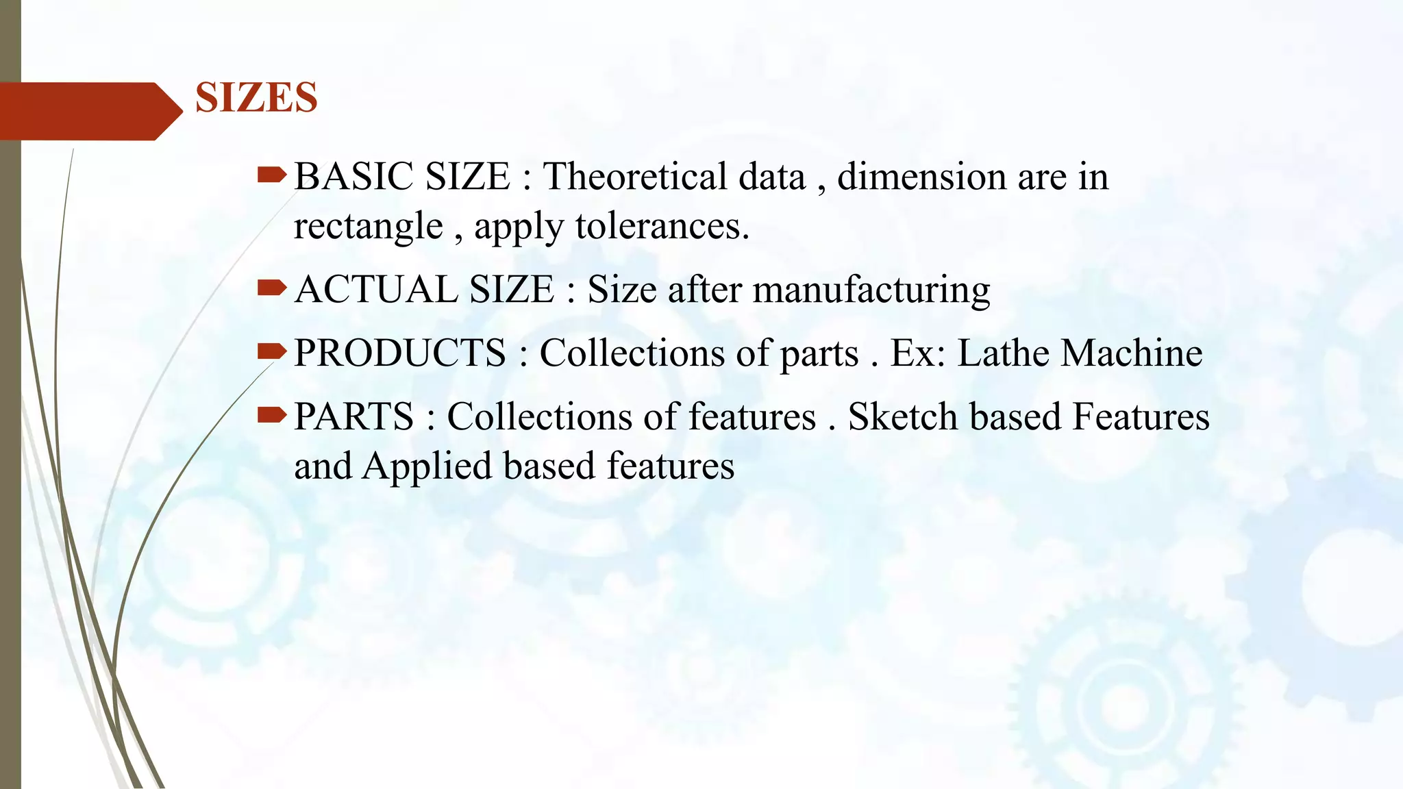
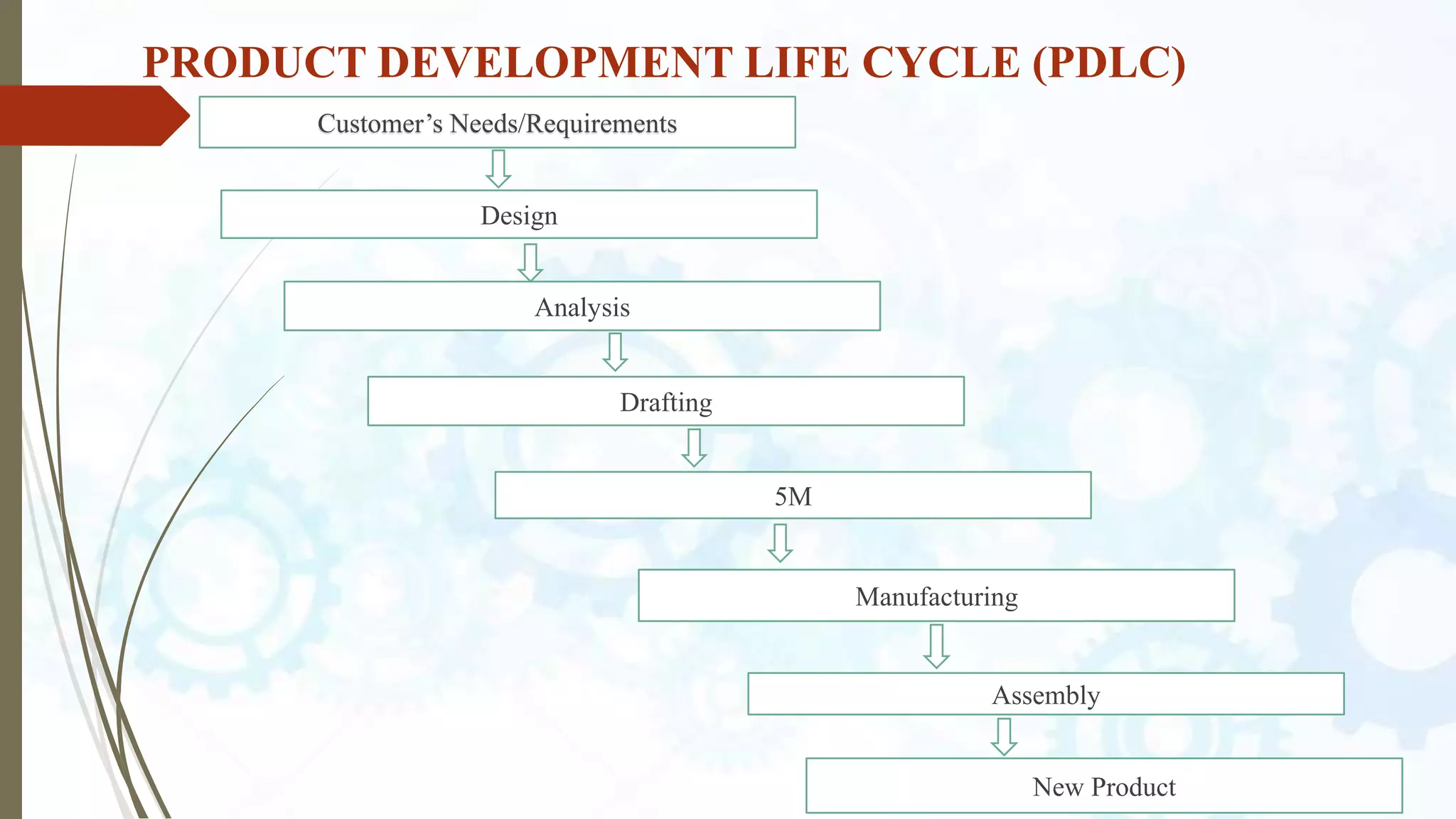
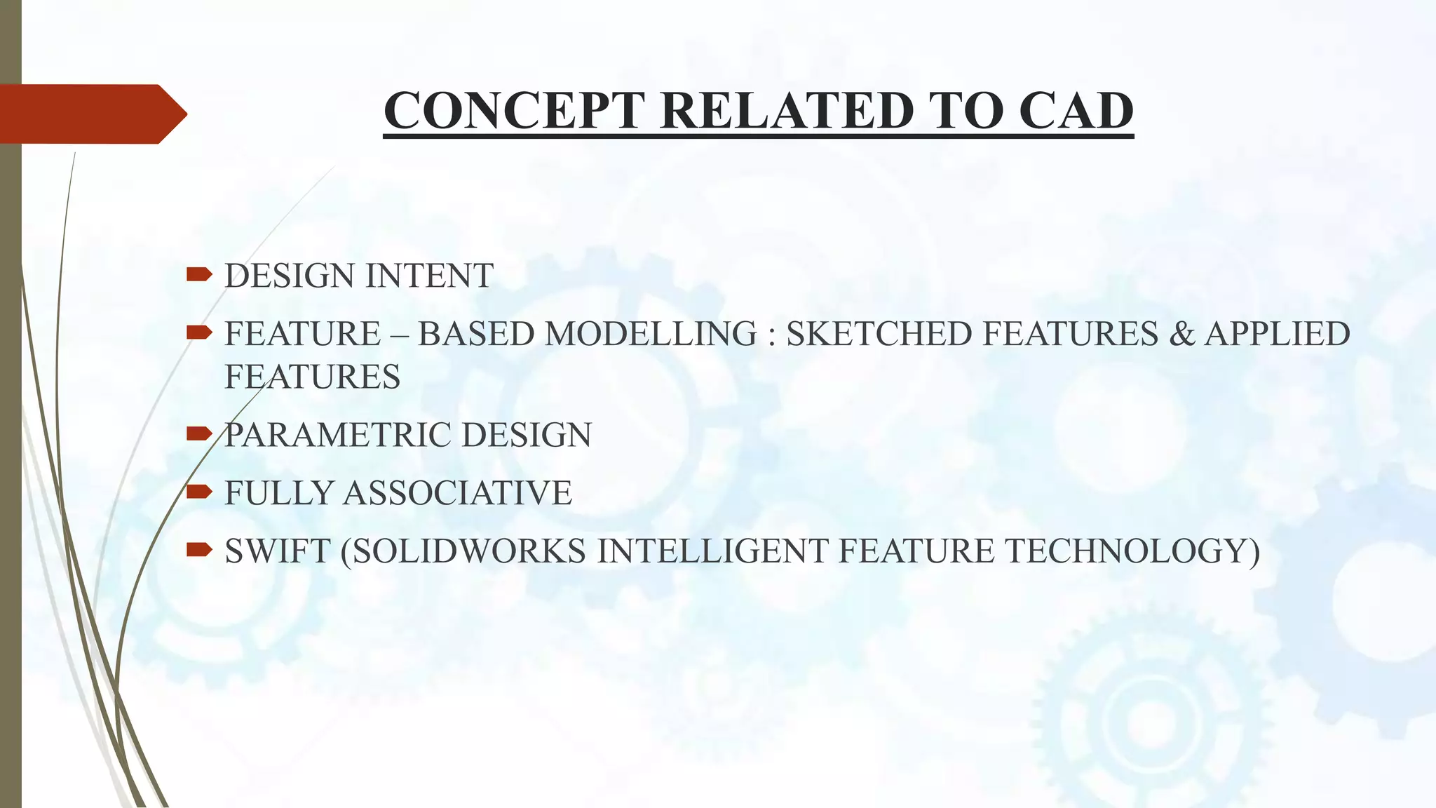
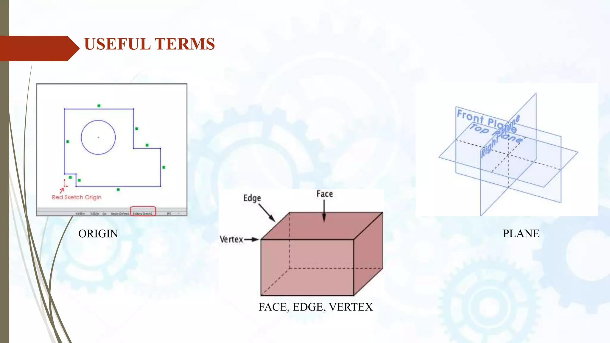
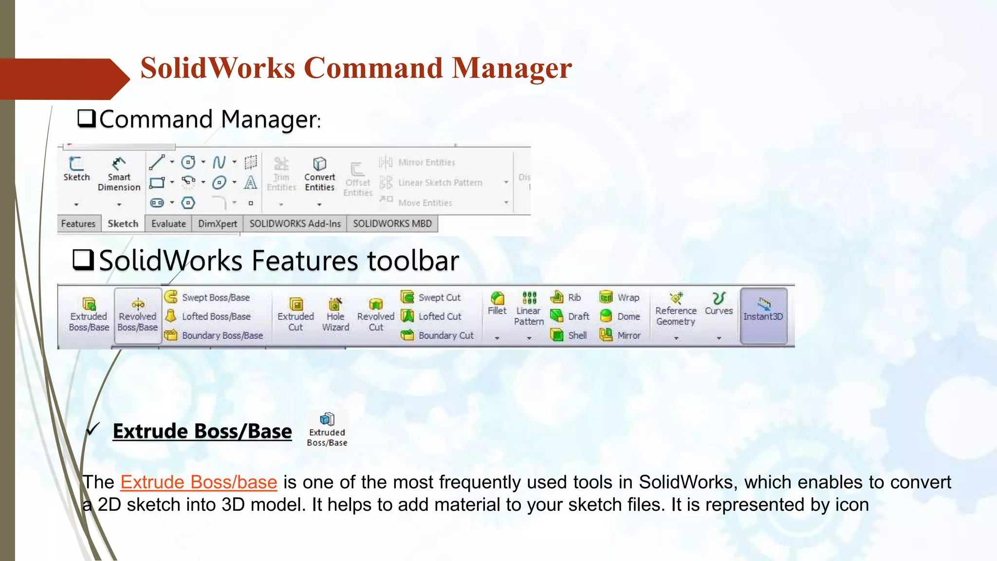

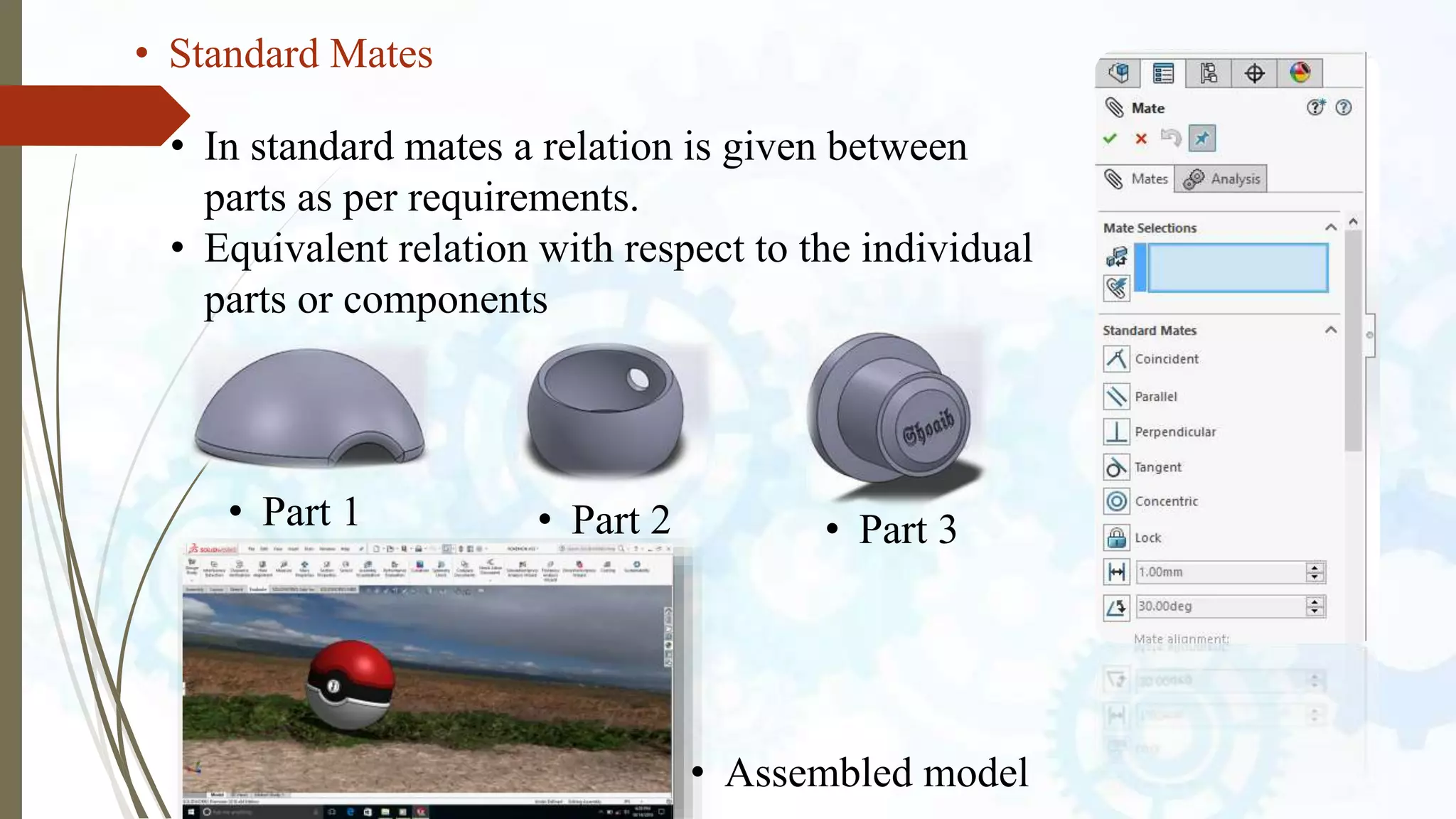
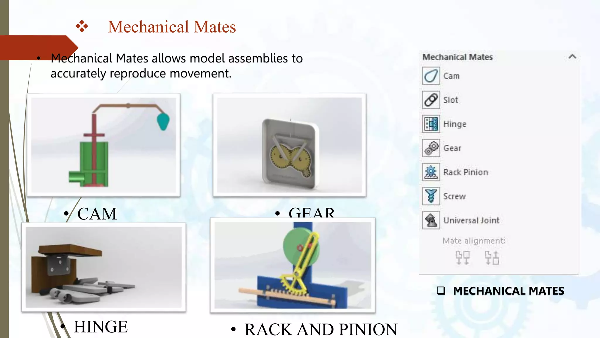
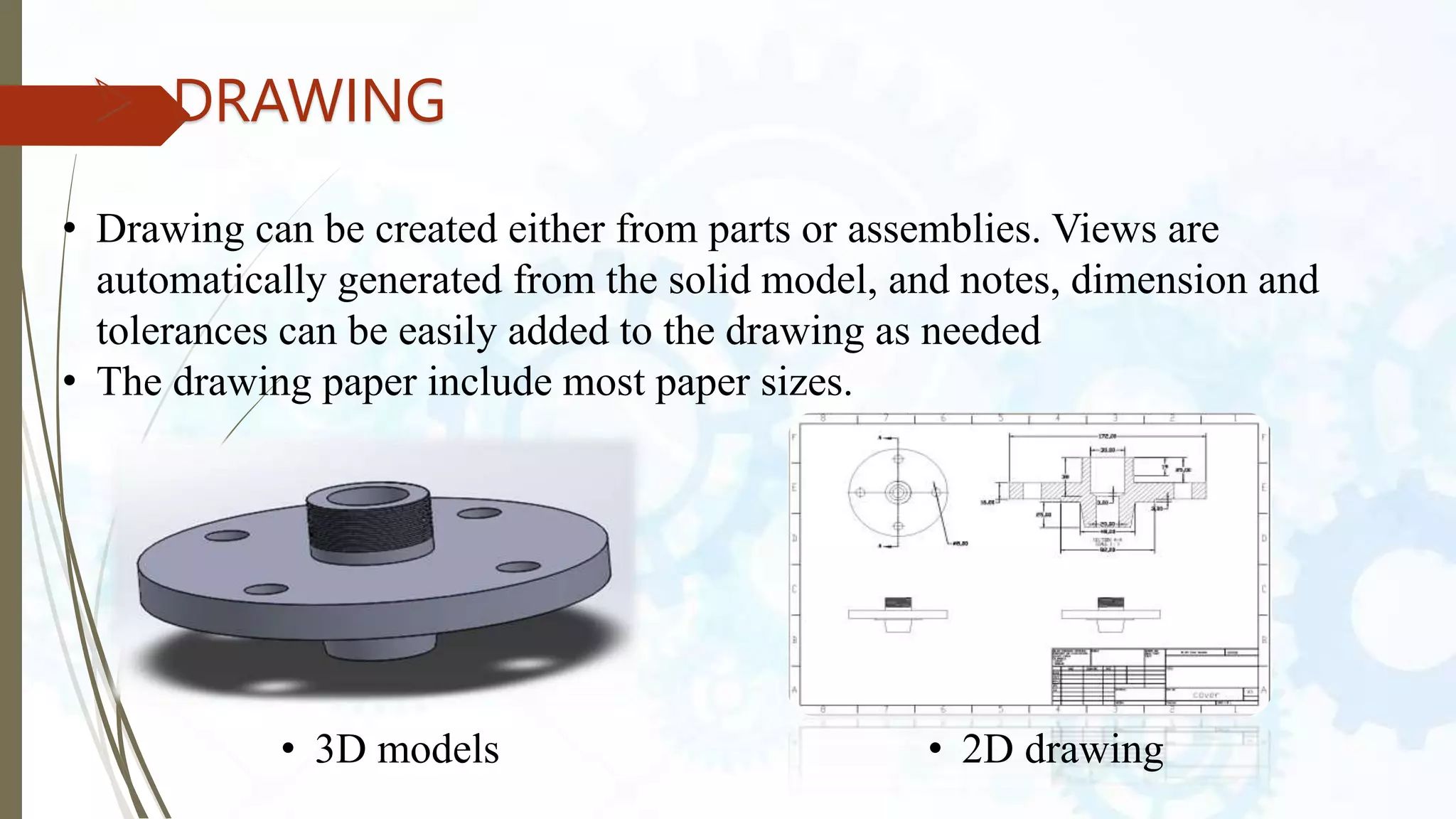

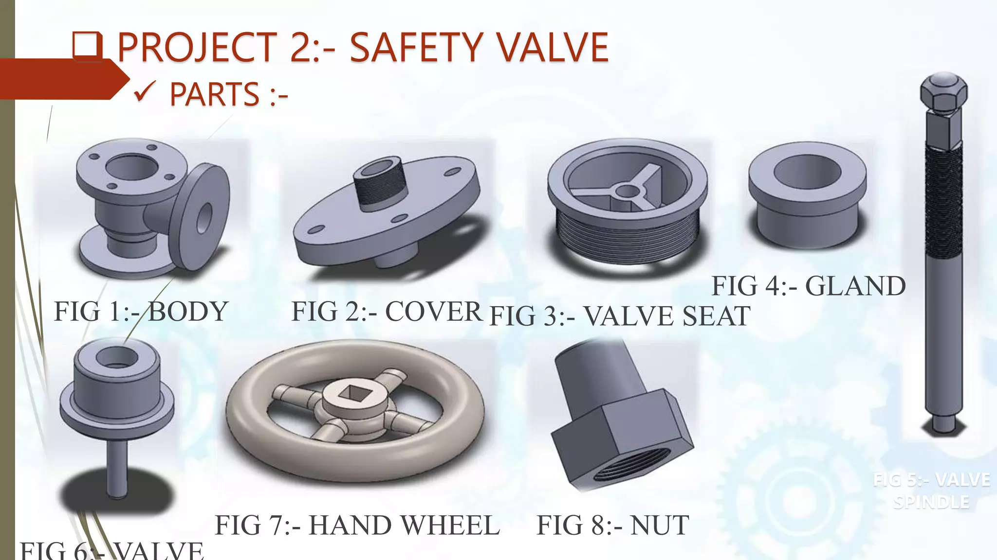
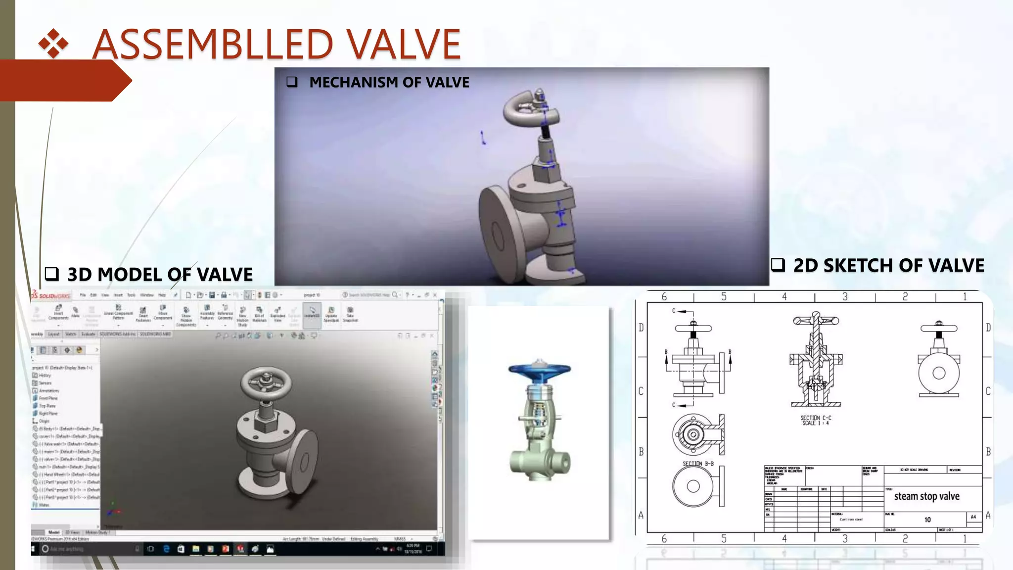


This document provides an introduction to SolidWorks, a 3D CAD software application. It discusses what SolidWorks is, some of its key features and benefits, and what types of design work can be done in SolidWorks, including 3D modeling, parametric modeling, assembly design, 2D drawing generation, simulation, and rendering. The document also covers SolidWorks concepts like design intent, feature-based modeling, and parametric design. Examples of projects that can be modeled in SolidWorks, like a gear train and nut-bolt assembly and a safety valve, are also presented.