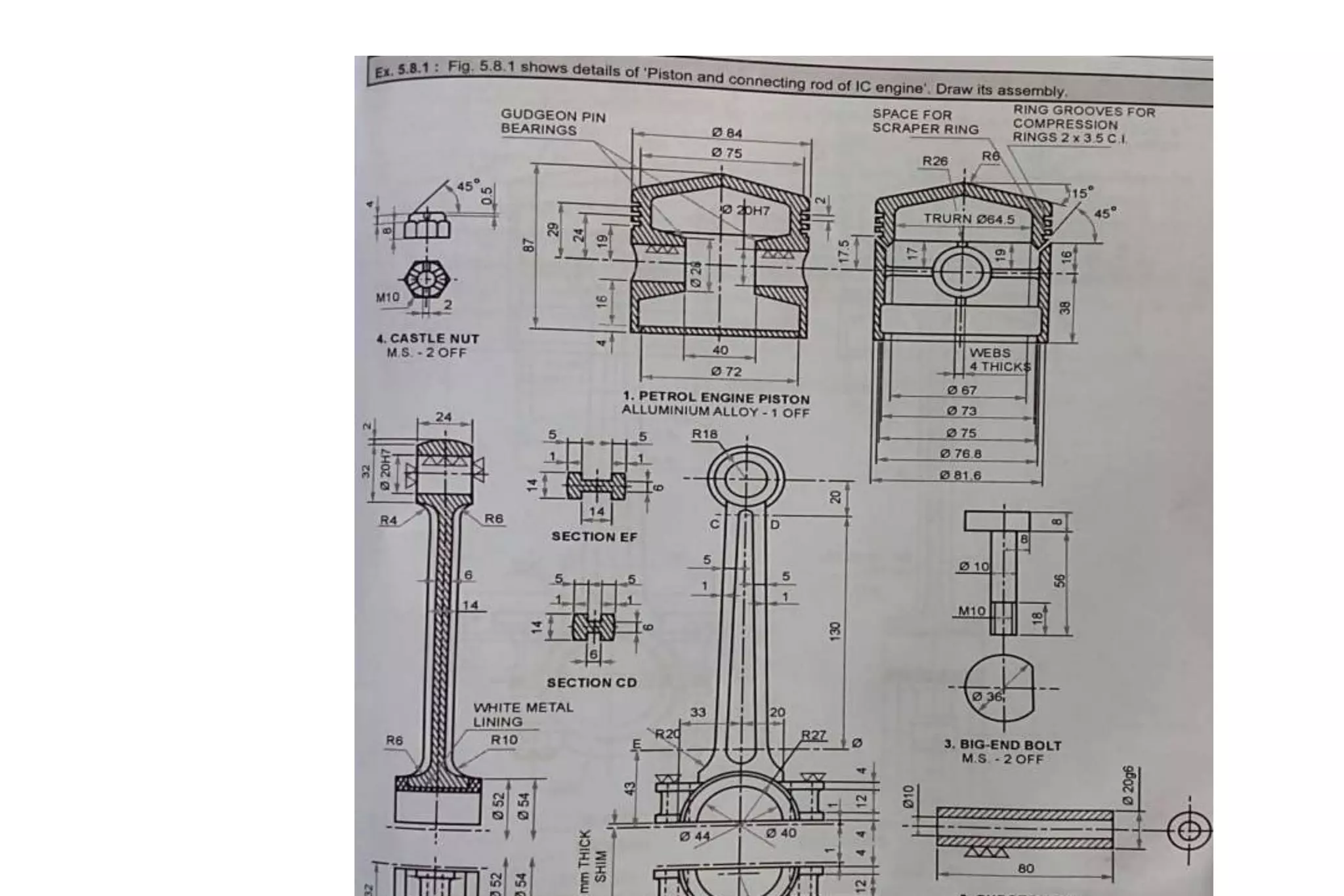
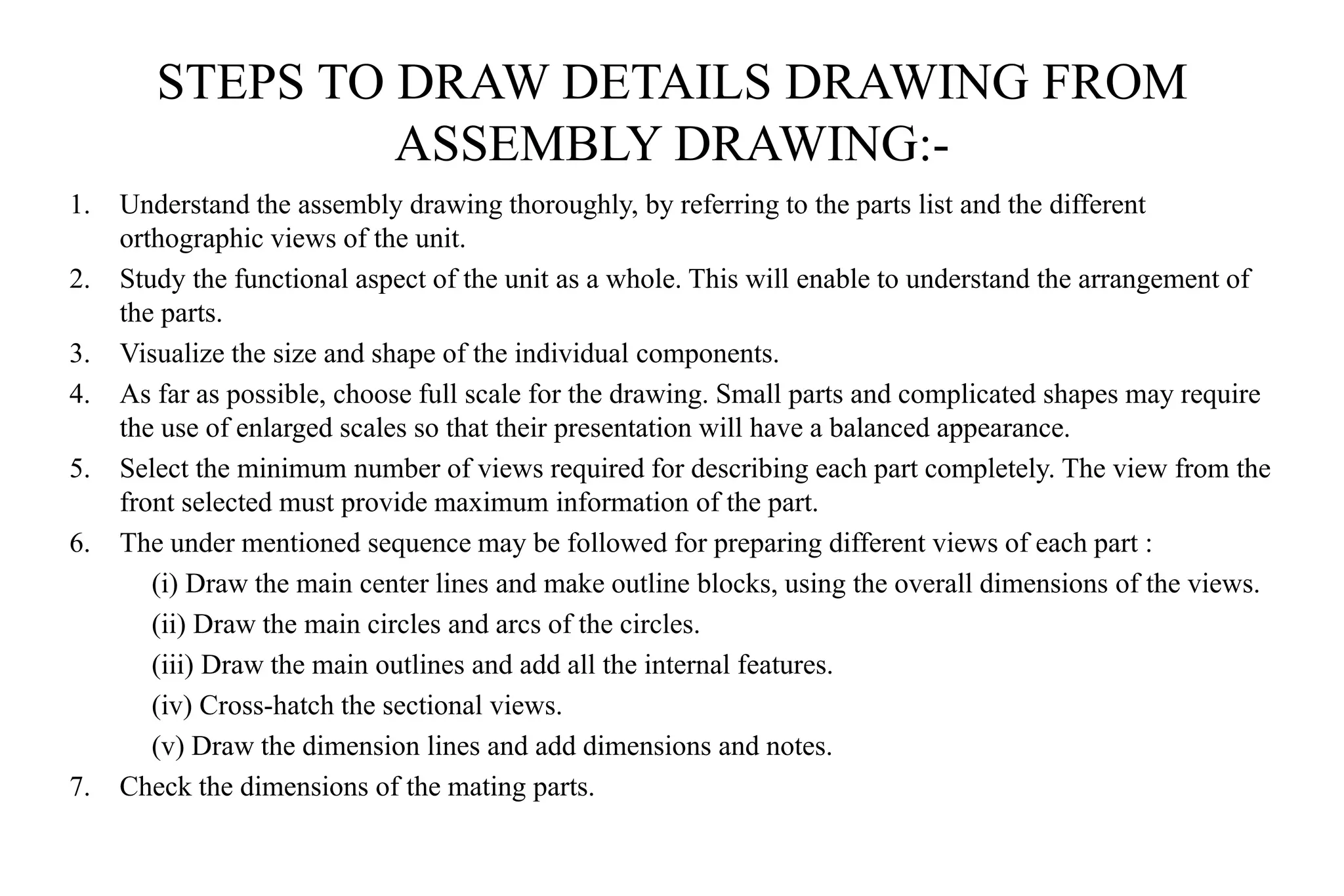
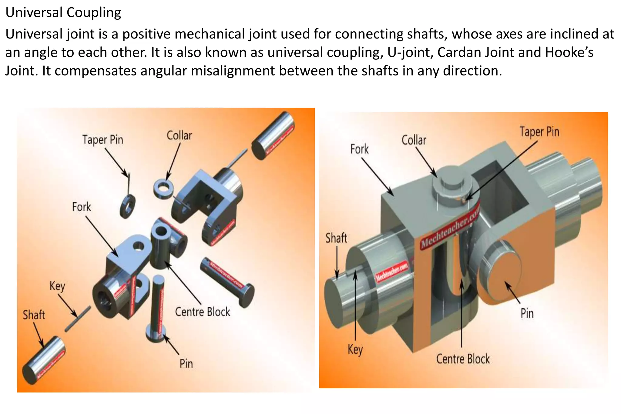
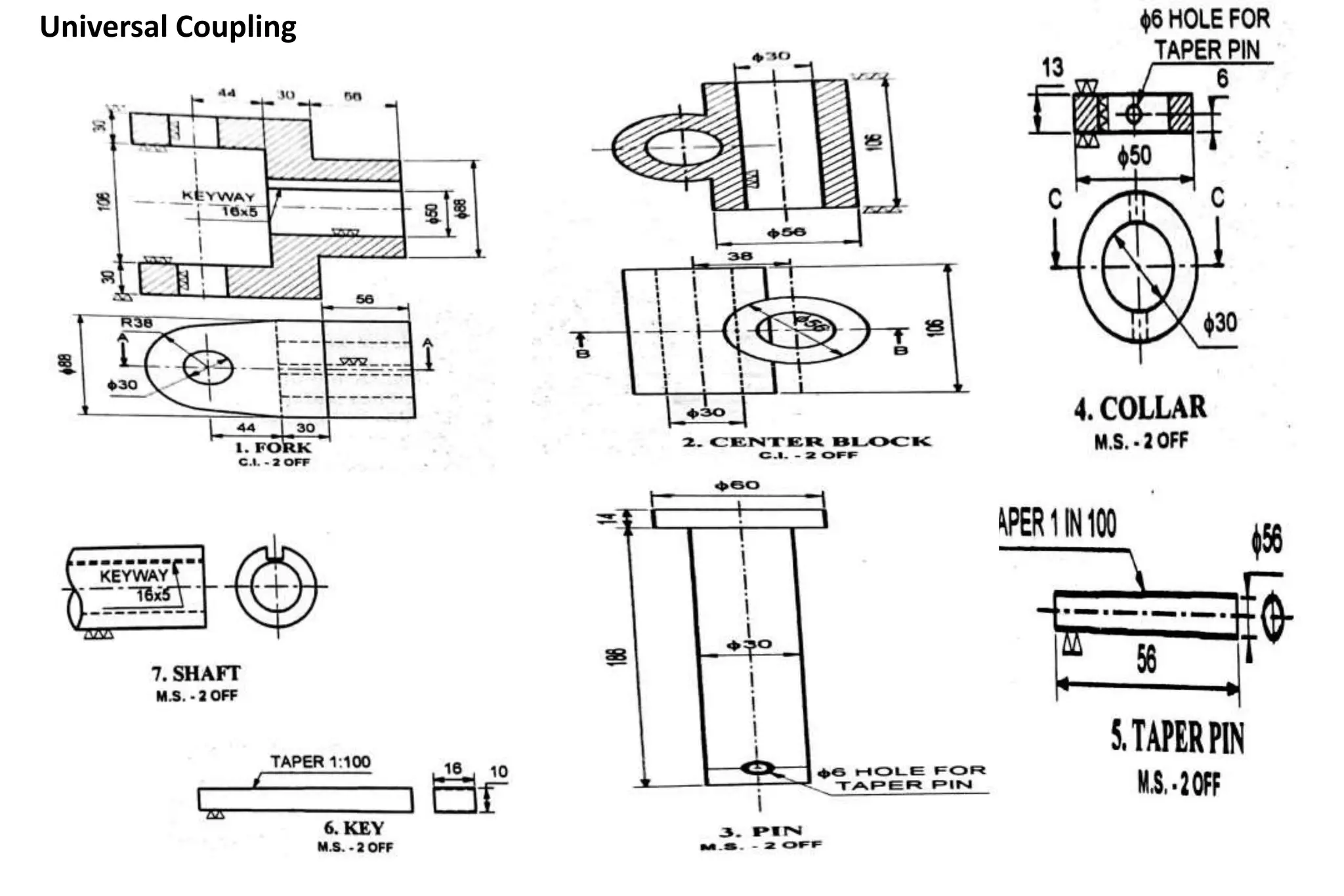
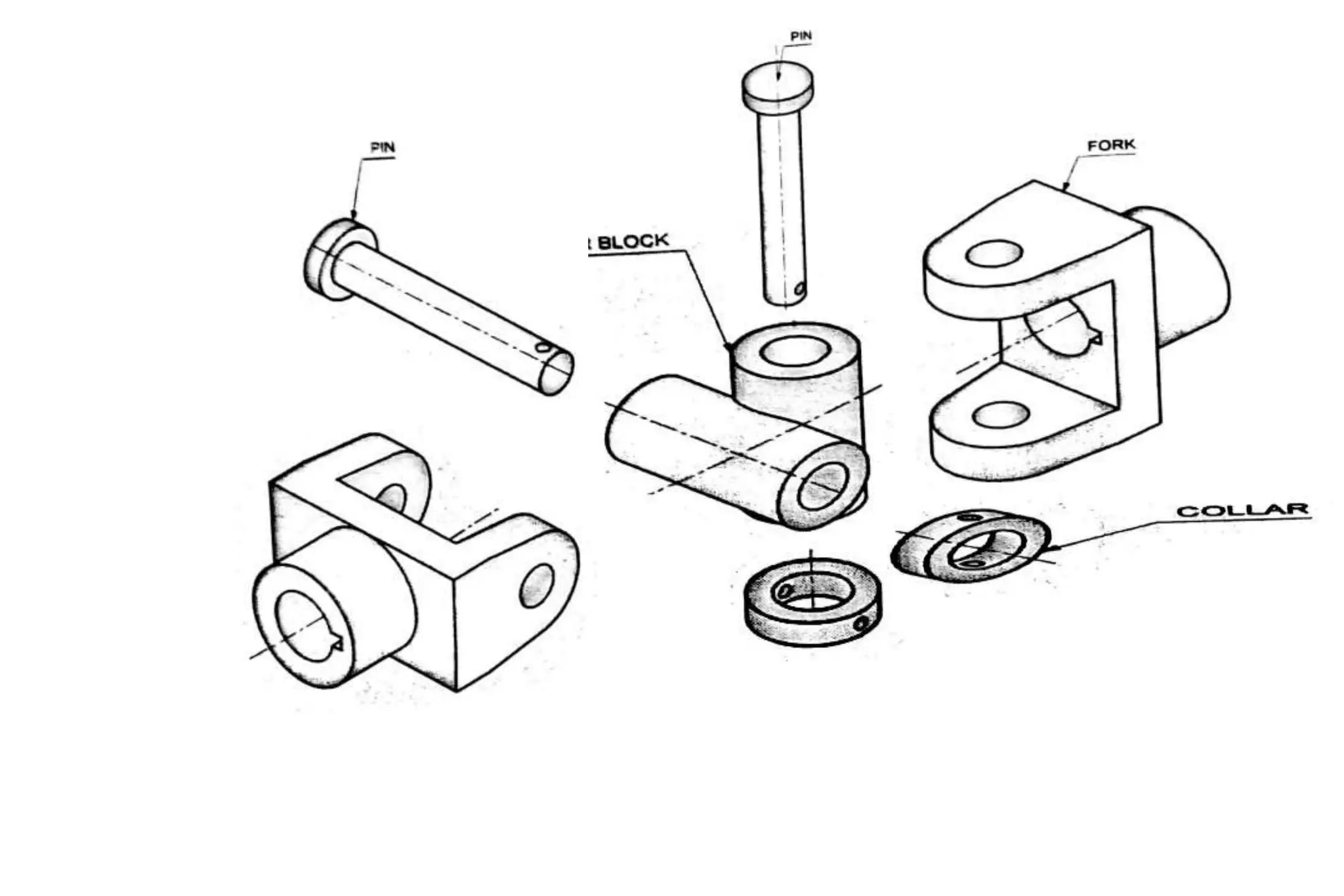
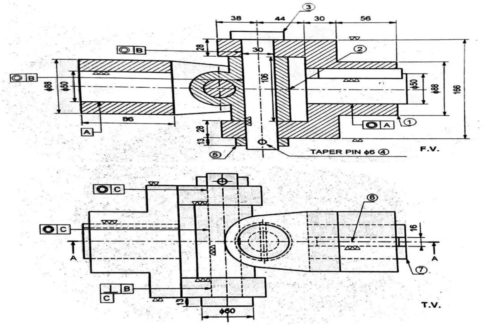
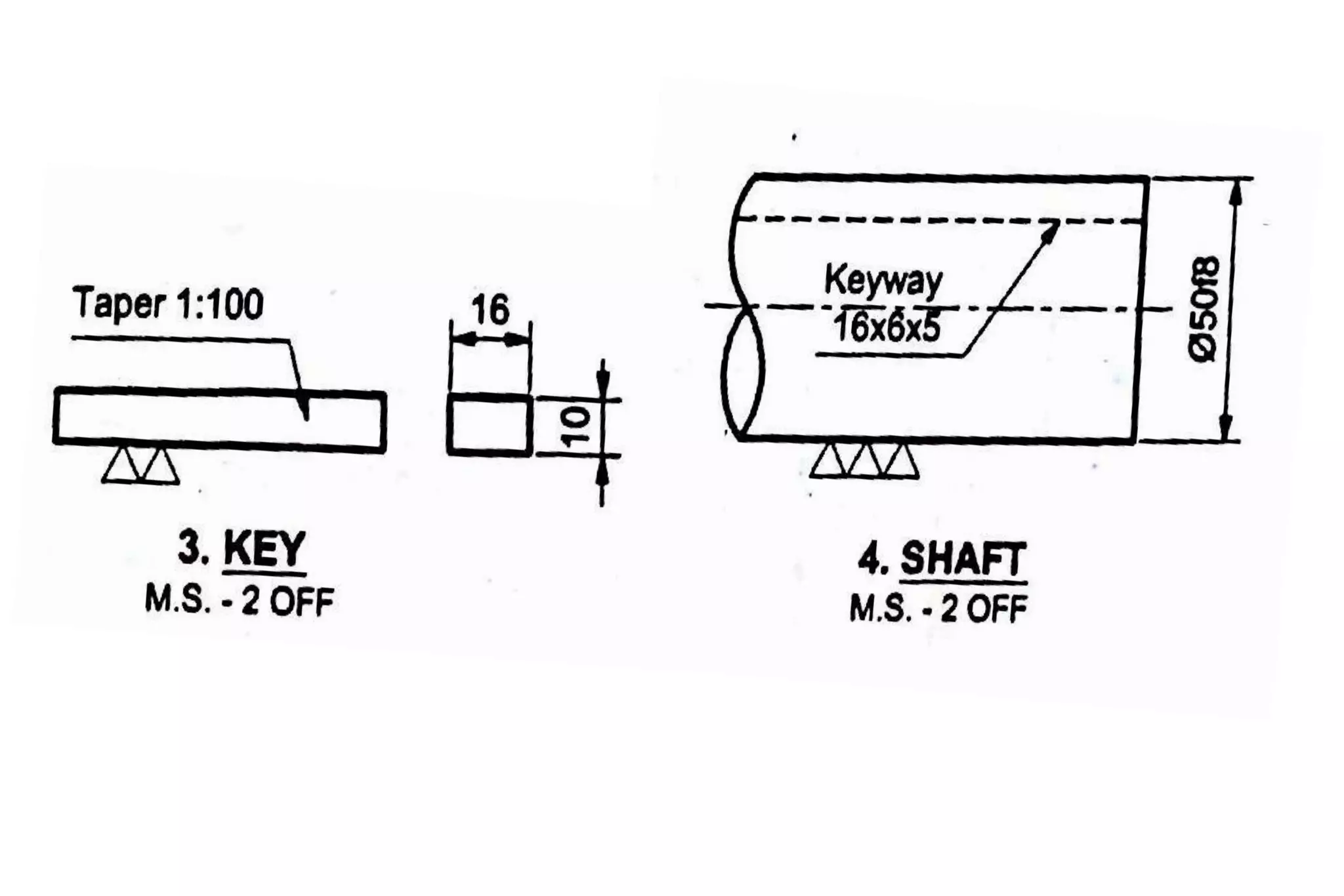
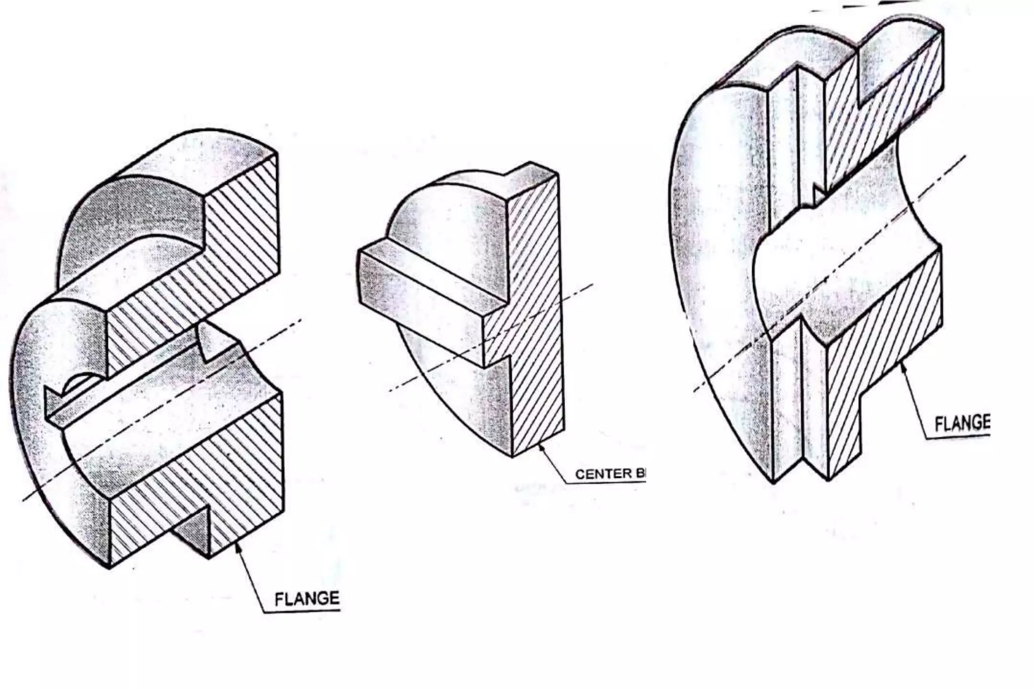
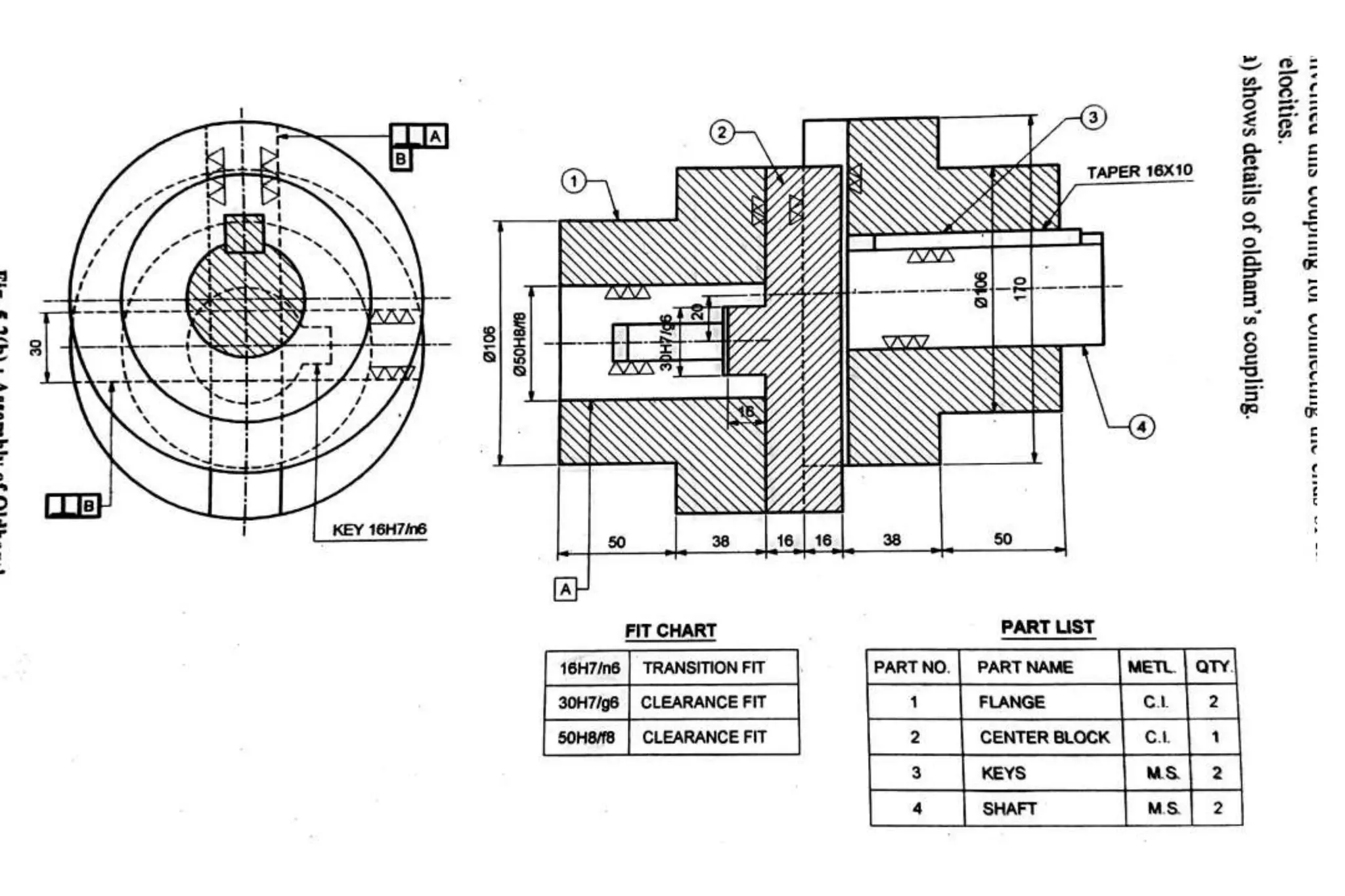
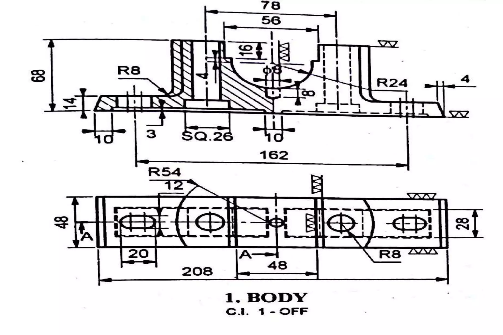
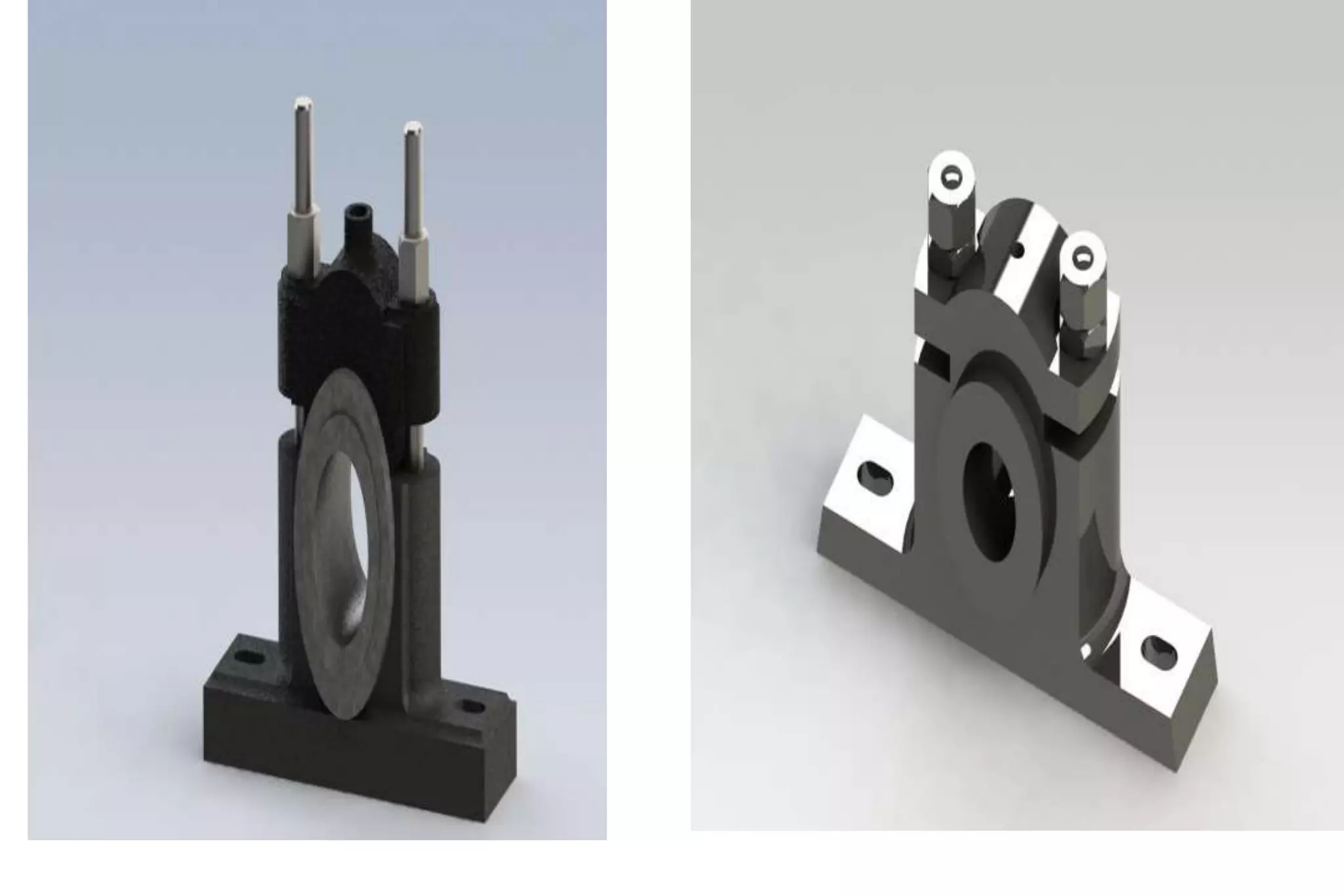
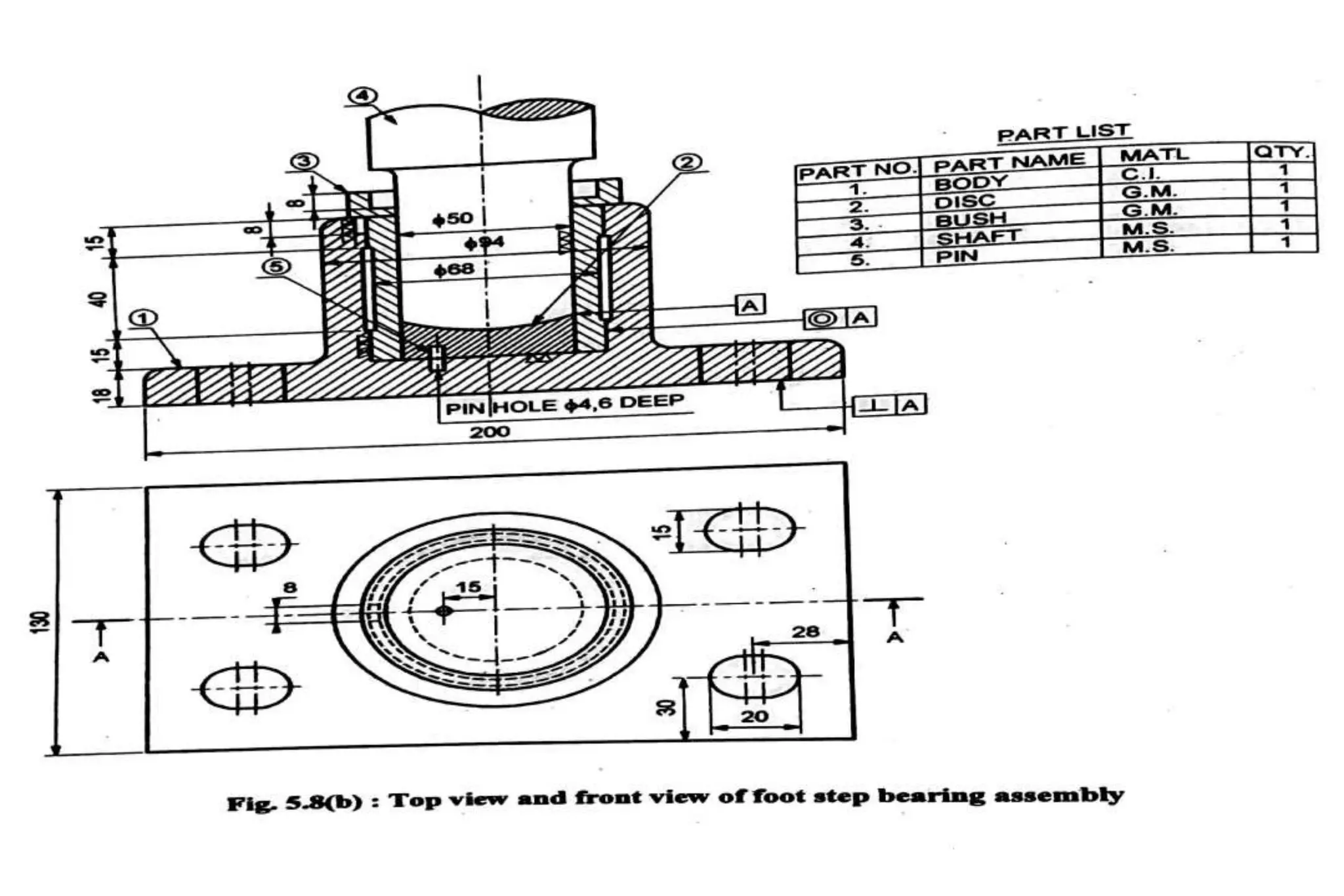
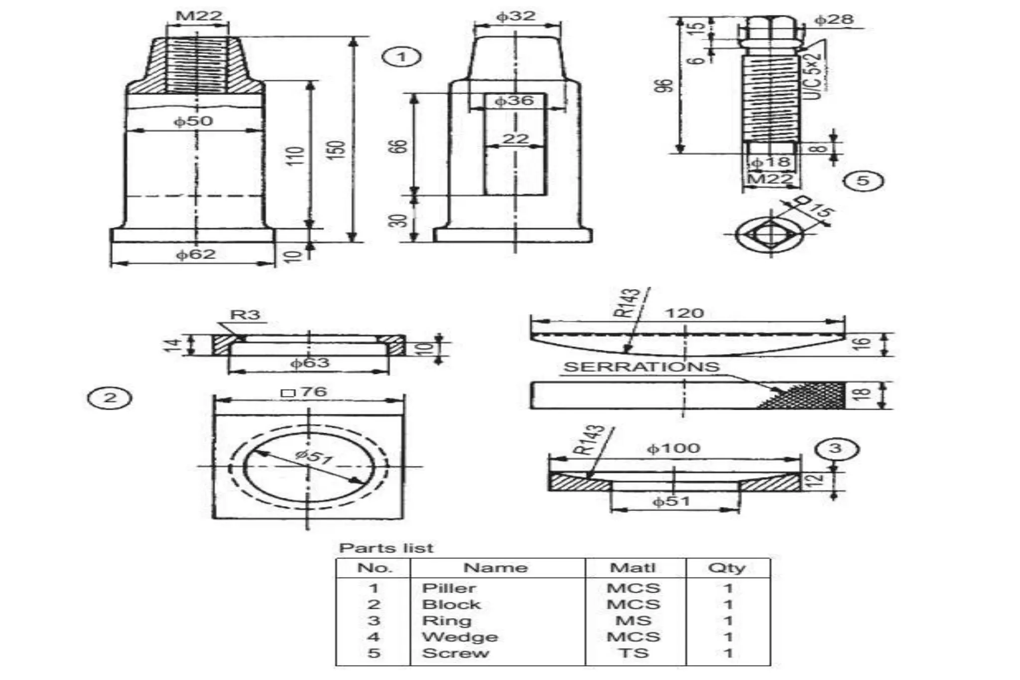
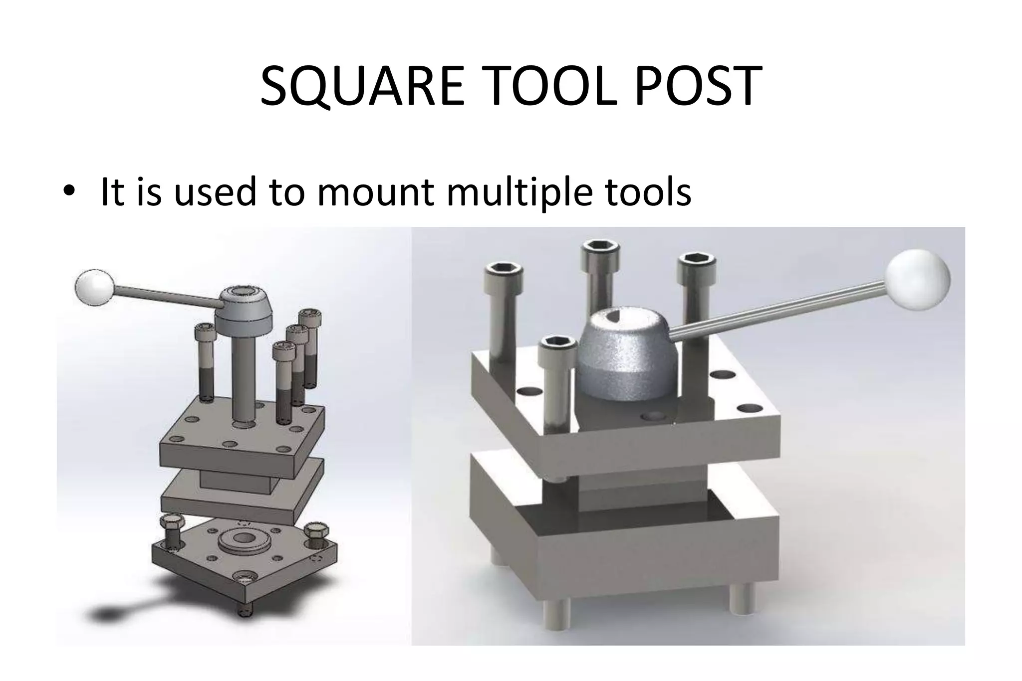
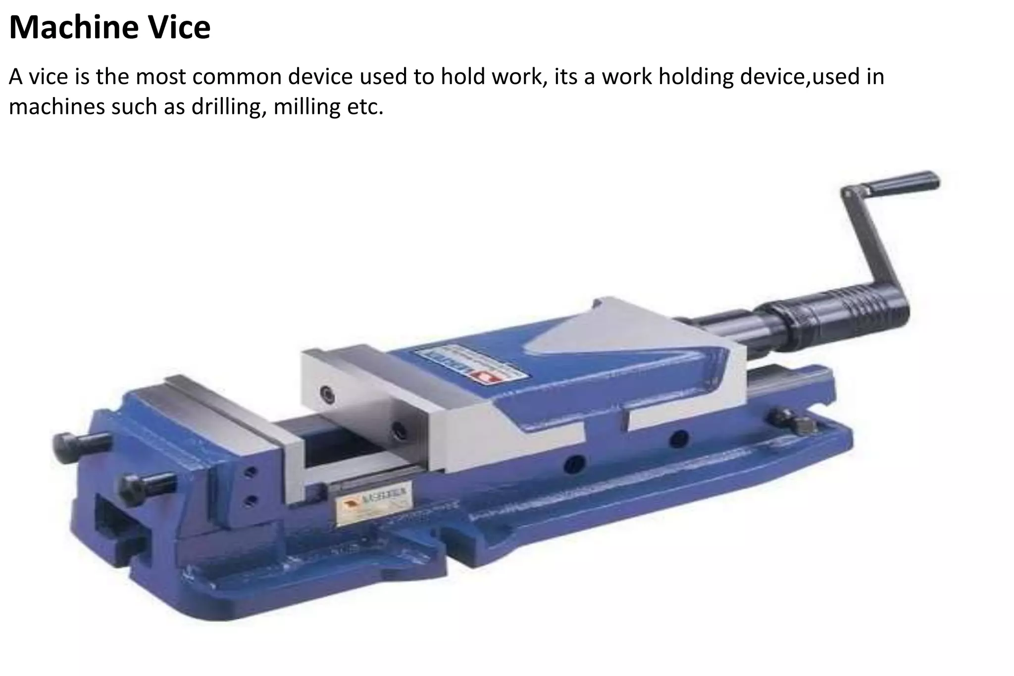
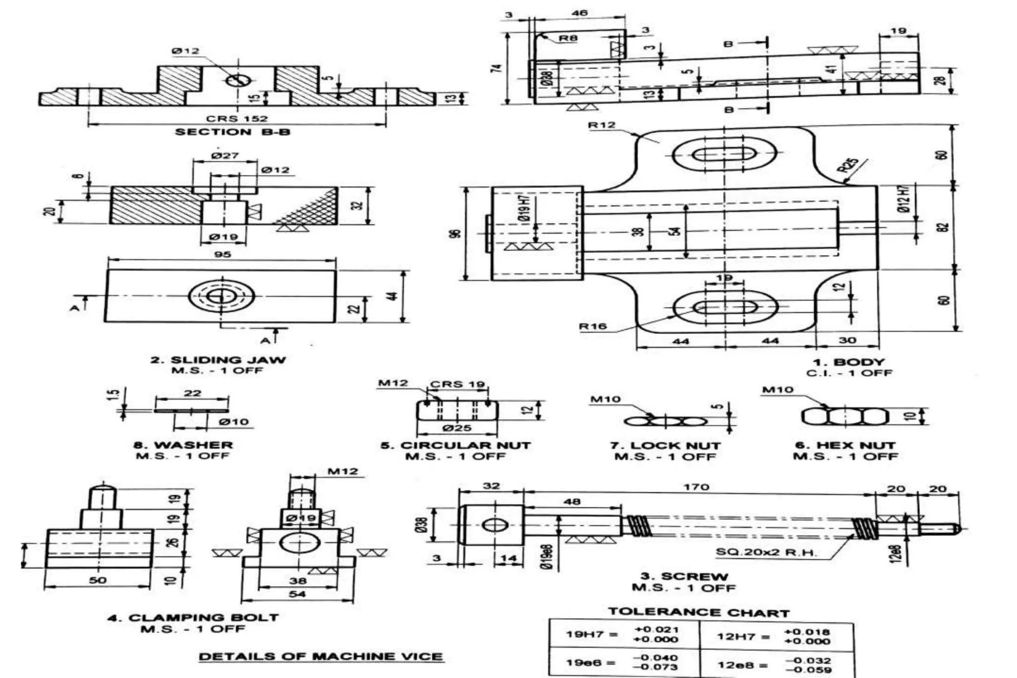
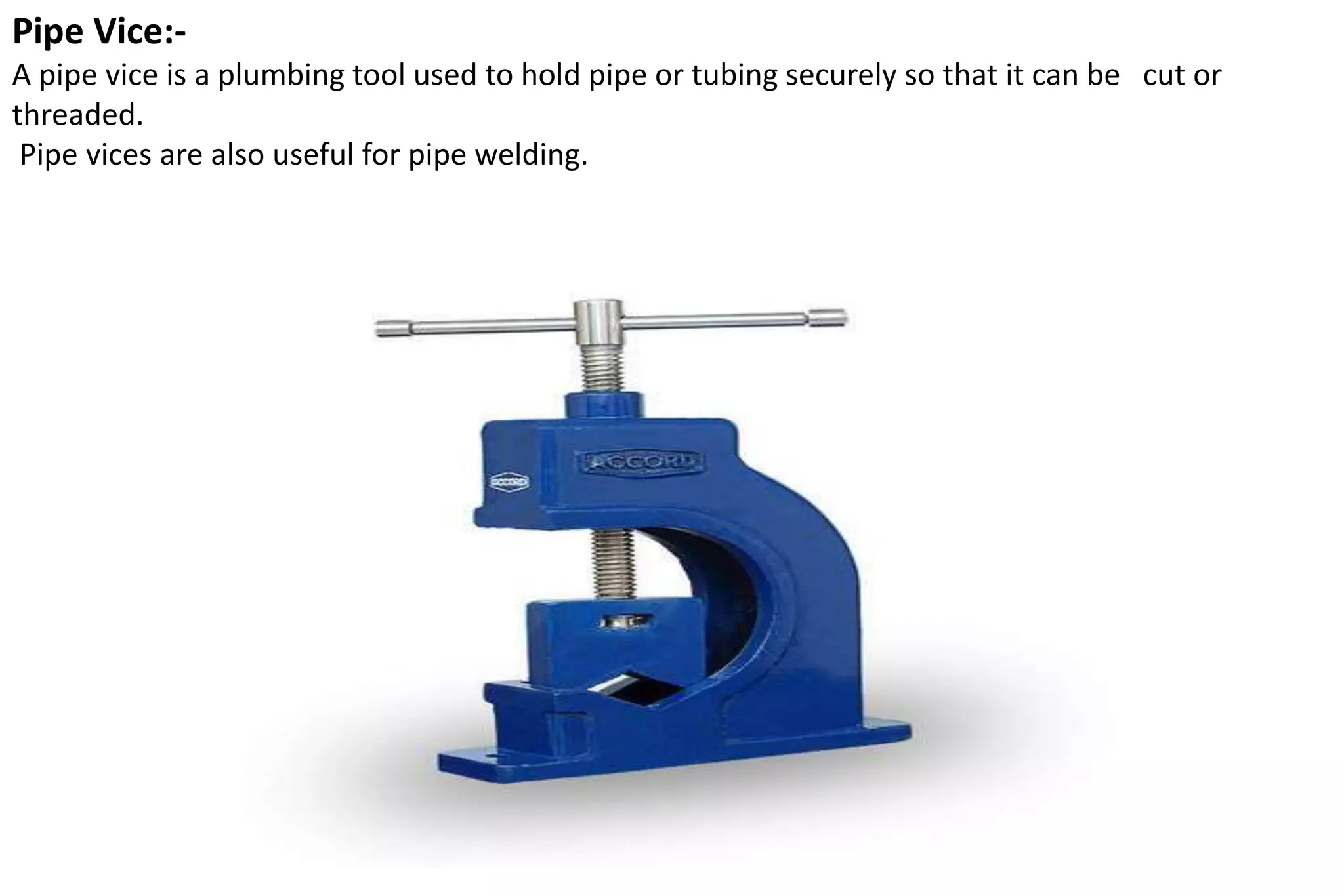
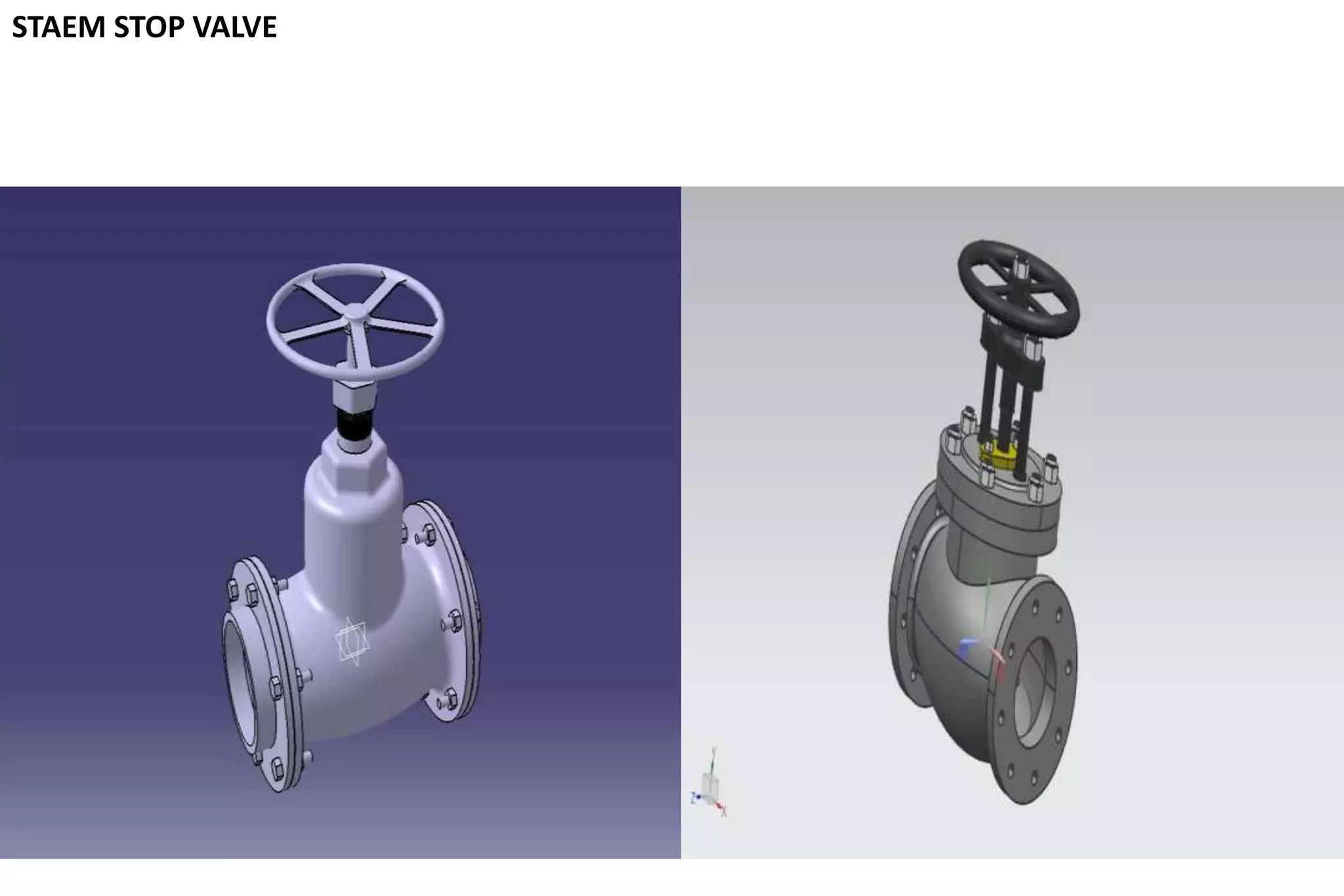
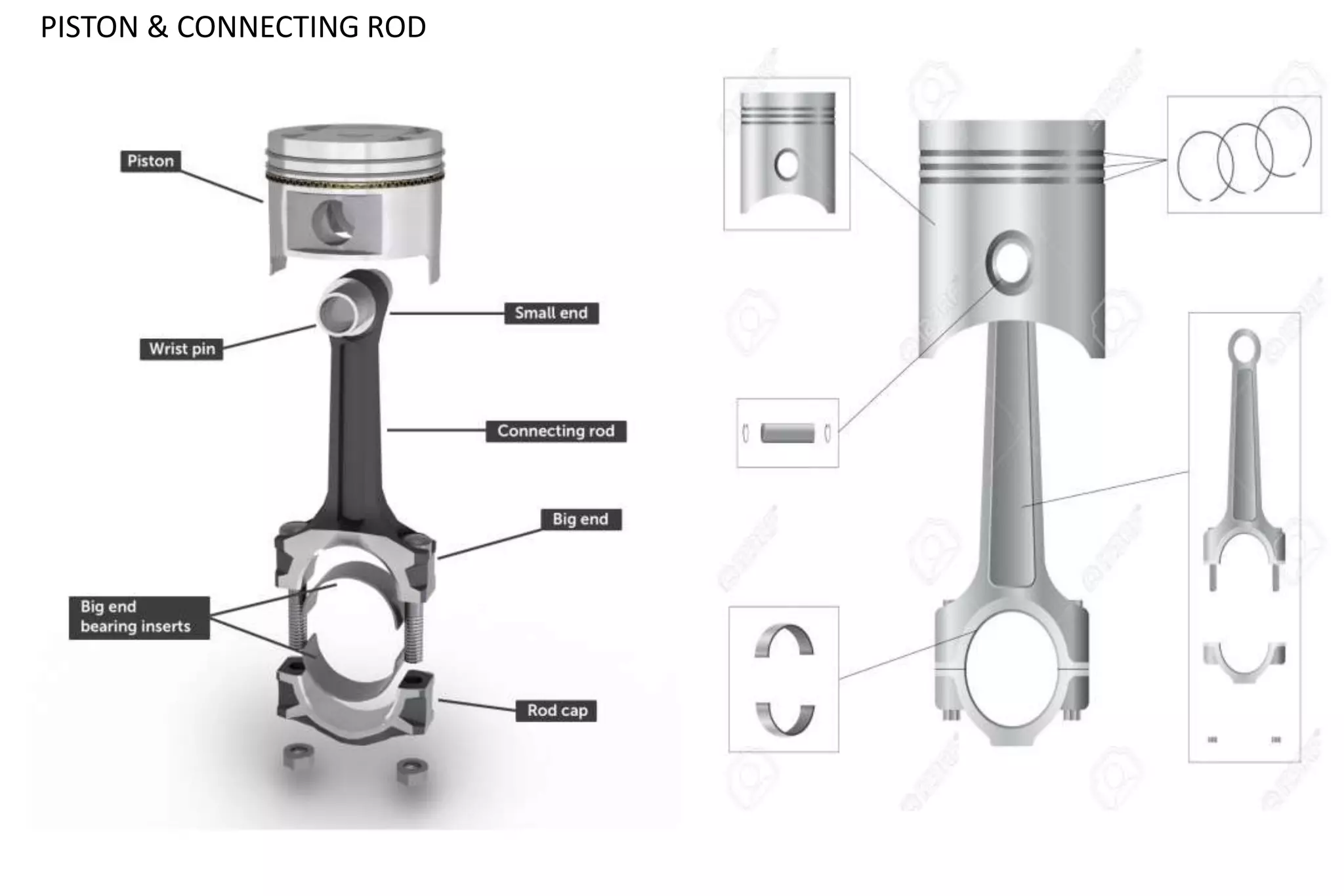
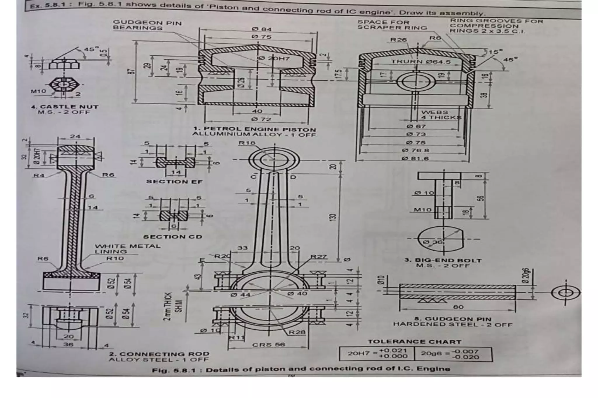
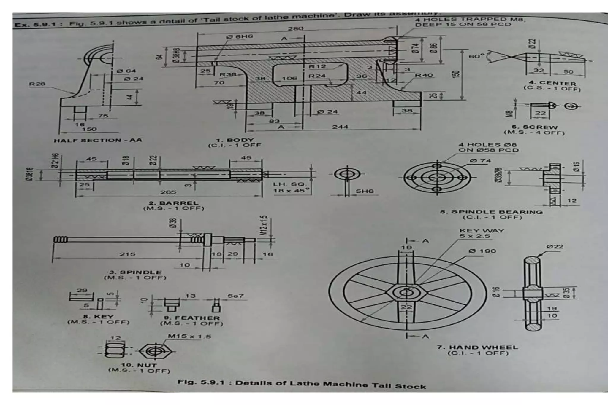
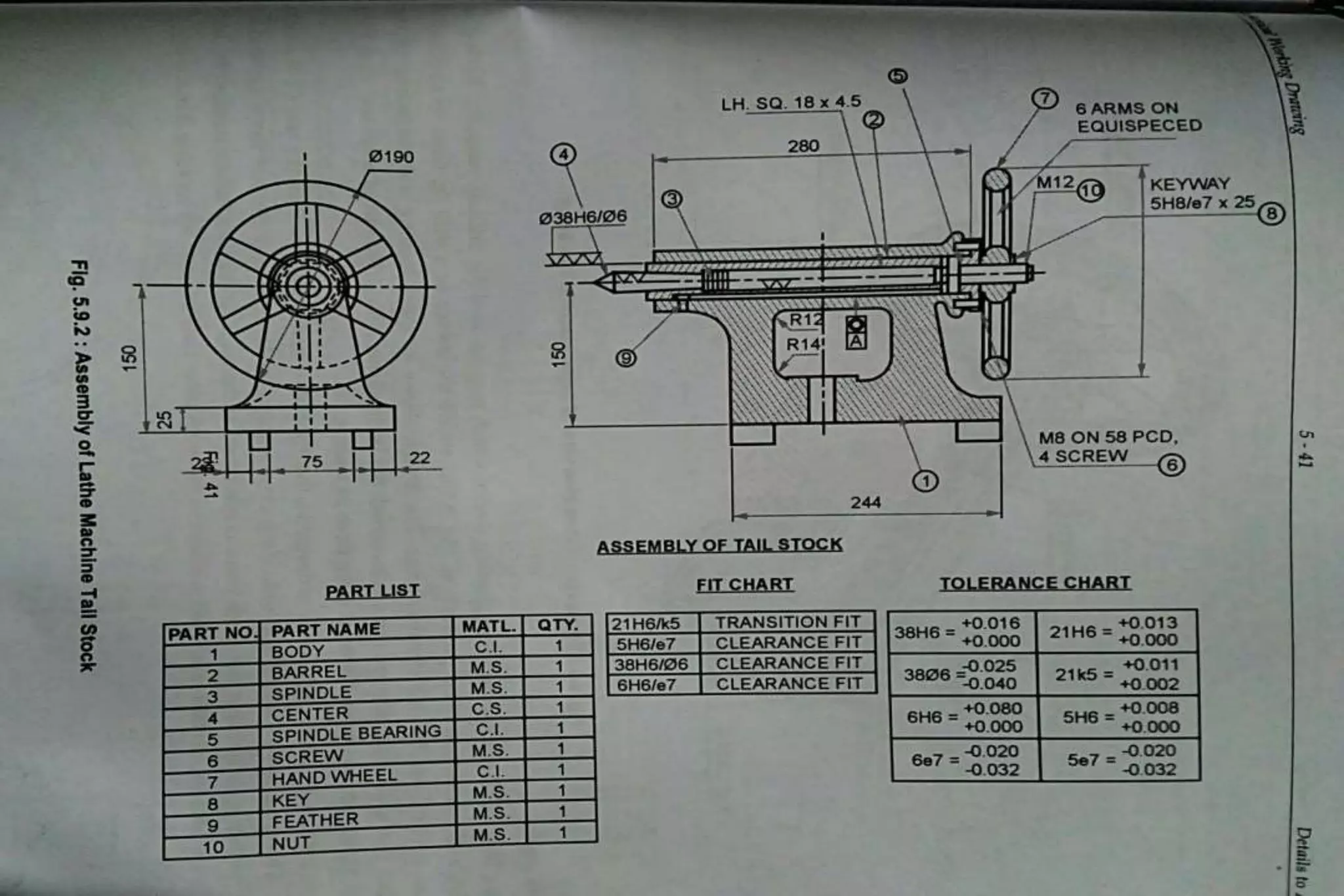
Unit V & VI
Details to Assembly & Assembly to
Details (32 Marks)
Class: SYME
Course: Mechanical Working Drawing (22341)
Academic Year: 2019-20
MR. MORE G.A.
LECTURER (MECHANICAL ENGINEERING DEPARTMENT)
( TSSM BSCOER POLYTECHNIC NARHE PUNE -41)
PISTON & CONNECTING ROD ASSEMBLY
Course Outcome & Unit Outcomes
Sr.
No.
Course Outcome
C341.
5
Draw assembly and detailed drawing of products
Sr.
No.
Unit Outcome
5.a. Explain the general procedure for assembly of components
5.b.
State details of components and sequence of components of the given
assembly
5.c. Draw assembly drawing from the given detailed drawing
STEPS TO DRAW ASSEMBLY DRAWING FROM
DETAILS DRAWING:-
1. Understand the purpose, principle of operation and field of application of the given
machine. This will help in understanding the functional requirements of individual parts
and their location.
2. Examine thoroughly, the external and internal features of the individual parts.
3. Choose a proper scale for the assembly drawing.
4. Estimate the overall dimensions of the views of the assembly drawing and make the
outline blocks for each of the required view, leaving enough space between them, for
indicating dimensions and adding required notes.
5. Draw the axes of symmetry for all the views of the assembly drawing.
6. Begin with the view from the front, by drawing first, the main parts of the machine and
then adding the rest of the parts, in the sequence of assembly.
7. Project the other required views from the view from the front complete views.
8. Mark the location and overall dimensions and add the part numbers on the drawing.
9. Prepare the parts list.
STEPS TO DRAW DETAILS DRAWING FROM
ASSEMBLY DRAWING:-
1. Understand the assembly drawing thoroughly, by referring to the parts list and the different
orthographic views of the unit.
2. Study the functional aspect of the unit as a whole. This will enable to understand the arrangement of
the parts.
3. Visualize the size and shape of the individual components.
4. As far as possible, choose full scale for the drawing. Small parts and complicated shapes may require
the use of enlarged scales so that their presentation will have a balanced appearance.
5. Select the minimum number of views required for describing each part completely. The view from the
front selected must provide maximum information of the part.
6. The under mentioned sequence may be followed for preparing different views of each part :
(i) Draw the main center lines and make outline blocks, using the overall dimensions of the views.
(ii) Draw the main circles and arcs of the circles.
(iii) Draw the main outlines and add all the internal features.
(iv) Cross-hatch the sectional views.
(v) Draw the dimension lines and add dimensions and notes.
7. Check the dimensions of the mating parts.
Types of Assembly Drawing
ASSEMBLY DRAWING
Design
Assembly
Drawing
Layout
Assembly
Drawing
Installation
Assembly
Drawing
General
Assembly
Drawing
Working
Assembly
Drawing
Prepare Part List (Bill of Material)
Part
No.
Part
Name
Mtl QTY
1 FORK CI 2
2 CETER
BLOCK
CI 1
3 PIN MS 2
4 TAPER
PIN
MS 2
5 COLLAR MS 2
6 KEY MS 2
7 SHAFT MS 2
Universal Coupling
Universal joint is a positive mechanical joint used for connecting shafts, whose axes are inclined at
an angle to each other. It is also known as universal coupling, U-joint, Cardan Joint and Hooke’s
Joint. It compensates angular misalignment between the shafts in any direction.
Universal Coupling
OLDHAM COUPLING
Oldham coupling is used to connect two shafts non parallel axis Oldham coupling
PLUMMER BLOCK
A pillow block (or plummer block) is a pedestal used to provide support for a rotating shaft with
the help of compatible bearings & various accessories.
FOOT STEP BEARING
A footstep bearing is usually in the form of a block that has a cavity in which the lower part of
a shaft can be fitted. It is designed to provide support to a vertical shaft or spindle.
LATHE TOOL POST
• It is used to mount single point cutting tool
SQUARE TOOL POST
• It is used to mount multiple tools
Machine Vice
A vice is the most common device used to hold work, its a work holding device,used in
machines such as drilling, milling etc.
Pipe Vice:-
A pipe vice is a plumbing tool used to hold pipe or tubing securely so that it can be cut or
threaded.
Pipe vices are also useful for pipe welding.
SCREW JACK
STAEM STOP VALVE
PISTON & CONNECTING ROD
LATHE TAILSTOCK
DRILL JIG
A jig's primary purpose is to provide repeatability, accuracy, and interchange ability in
the manufacturing of products. A jig is often confused with a fixture; a fixture holds the
work in a fixed location. A device that does both functions (holding the work and guiding a
tool) is called a jig.
ASSEMBLY TO DETAILS OF MECHINE COMPONENTS

ASSEMBLY TO DETAILS OF MECHINE COMPONENTS

  • 1.
    Unit V &VI Details to Assembly & Assembly to Details (32 Marks) Class: SYME Course: Mechanical Working Drawing (22341) Academic Year: 2019-20 MR. MORE G.A. LECTURER (MECHANICAL ENGINEERING DEPARTMENT) ( TSSM BSCOER POLYTECHNIC NARHE PUNE -41)
  • 2.
    PISTON & CONNECTINGROD ASSEMBLY
  • 4.
    Course Outcome &Unit Outcomes Sr. No. Course Outcome C341. 5 Draw assembly and detailed drawing of products Sr. No. Unit Outcome 5.a. Explain the general procedure for assembly of components 5.b. State details of components and sequence of components of the given assembly 5.c. Draw assembly drawing from the given detailed drawing
  • 5.
    STEPS TO DRAWASSEMBLY DRAWING FROM DETAILS DRAWING:- 1. Understand the purpose, principle of operation and field of application of the given machine. This will help in understanding the functional requirements of individual parts and their location. 2. Examine thoroughly, the external and internal features of the individual parts. 3. Choose a proper scale for the assembly drawing. 4. Estimate the overall dimensions of the views of the assembly drawing and make the outline blocks for each of the required view, leaving enough space between them, for indicating dimensions and adding required notes. 5. Draw the axes of symmetry for all the views of the assembly drawing. 6. Begin with the view from the front, by drawing first, the main parts of the machine and then adding the rest of the parts, in the sequence of assembly. 7. Project the other required views from the view from the front complete views. 8. Mark the location and overall dimensions and add the part numbers on the drawing. 9. Prepare the parts list.
  • 6.
    STEPS TO DRAWDETAILS DRAWING FROM ASSEMBLY DRAWING:- 1. Understand the assembly drawing thoroughly, by referring to the parts list and the different orthographic views of the unit. 2. Study the functional aspect of the unit as a whole. This will enable to understand the arrangement of the parts. 3. Visualize the size and shape of the individual components. 4. As far as possible, choose full scale for the drawing. Small parts and complicated shapes may require the use of enlarged scales so that their presentation will have a balanced appearance. 5. Select the minimum number of views required for describing each part completely. The view from the front selected must provide maximum information of the part. 6. The under mentioned sequence may be followed for preparing different views of each part : (i) Draw the main center lines and make outline blocks, using the overall dimensions of the views. (ii) Draw the main circles and arcs of the circles. (iii) Draw the main outlines and add all the internal features. (iv) Cross-hatch the sectional views. (v) Draw the dimension lines and add dimensions and notes. 7. Check the dimensions of the mating parts.
  • 7.
    Types of AssemblyDrawing ASSEMBLY DRAWING Design Assembly Drawing Layout Assembly Drawing Installation Assembly Drawing General Assembly Drawing Working Assembly Drawing
  • 8.
    Prepare Part List(Bill of Material) Part No. Part Name Mtl QTY 1 FORK CI 2 2 CETER BLOCK CI 1 3 PIN MS 2 4 TAPER PIN MS 2 5 COLLAR MS 2 6 KEY MS 2 7 SHAFT MS 2
  • 9.
    Universal Coupling Universal jointis a positive mechanical joint used for connecting shafts, whose axes are inclined at an angle to each other. It is also known as universal coupling, U-joint, Cardan Joint and Hooke’s Joint. It compensates angular misalignment between the shafts in any direction.
  • 10.
  • 13.
    OLDHAM COUPLING Oldham couplingis used to connect two shafts non parallel axis Oldham coupling
  • 20.
    PLUMMER BLOCK A pillowblock (or plummer block) is a pedestal used to provide support for a rotating shaft with the help of compatible bearings & various accessories.
  • 30.
    FOOT STEP BEARING Afootstep bearing is usually in the form of a block that has a cavity in which the lower part of a shaft can be fitted. It is designed to provide support to a vertical shaft or spindle.
  • 35.
    LATHE TOOL POST •It is used to mount single point cutting tool
  • 38.
    SQUARE TOOL POST •It is used to mount multiple tools
  • 40.
    Machine Vice A viceis the most common device used to hold work, its a work holding device,used in machines such as drilling, milling etc.
  • 44.
    Pipe Vice:- A pipevice is a plumbing tool used to hold pipe or tubing securely so that it can be cut or threaded. Pipe vices are also useful for pipe welding.
  • 46.
  • 47.
  • 49.
  • 52.
  • 55.
    DRILL JIG A jig'sprimary purpose is to provide repeatability, accuracy, and interchange ability in the manufacturing of products. A jig is often confused with a fixture; a fixture holds the work in a fixed location. A device that does both functions (holding the work and guiding a tool) is called a jig.