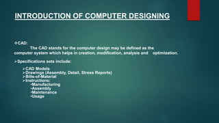
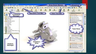
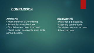
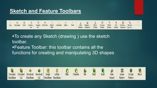
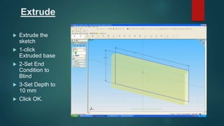
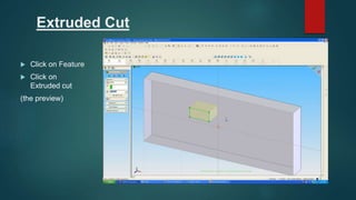
PRESENTED BY:-
MD FIRDOUS ALAM
OUTLINE
 INTRODUCTION OF COMPUTER DESIGNING
 SOME COMMONLY USED DESINING SOFTWARES
 INTRODUCTION
 COMPARISON
 MODIFY COMMANDS
 SKETCH AND FEATURE TOOLBARS
 DESIGN A PART
 ASSEMBLY
 DRAWING TEMPLATE AND DRAWING FORMAT
INTRODUCTION OF COMPUTER DESIGNING
CAD:
The CAD stands for the computer design may be defined as the
computer system which helps in creation, modification, analysis and optimization.
Specifications sets include:
CAD Models
Drawings (Assembly, Detail, Stress Reports)
Bills-of-Material
Instructions:
•Manufacturing
•Assembly
•Maintenance
•Usage
SOME COMMONLY USED DESINING SOFTWARES
 AUTOCAD
SOLIDWORKS
PRO-E
CATIA
ANSYS
SOLID EDGE
INTRODUCTION
 This is a Powerful and User-friendly software to design
3D model of Mechanical parts and Assembly's,
Drawings to manufacture , analysis and so on.
 Its Initial release was in 1995
 Solidworks is currently used by over 2 million
engineers and more than 165,000 companies
worldwide.
COMPARISON
AUTOCAD
• Most prefer for 2-D modeling.
• Assembly cannot be done.
• Simulation test cannot be done.
• Sheet metal, weldments, mold tools
cannot be done.
SOLIDWORKS
• Prefer for 3-d modeling.
• Assembly can be done.
• Simulation test can be done.
• All can be done.
Modify commands:
 Erase
 Copy
 Mirror
 Fillet
 Chamfer
 Offset Entities
 Rotate
 Extend
 Trim
 Scale
 Zoom
The SolidWorks Model
The SolidWorks model is made up of:
 Parts
 Assemblies
 Drawings
Sketch and Feature Toolbars
To create any Sketch (drawing ) use the sketch
toolbar.
Feature Toolbar: this toolbar contains all the
functions for creating and manipulating 3D shapes
Design a Part
 Every part is composed of a
sketch and a feature
 1- Go to Sketch Mode and Draw a
2D sketch(sketch is a drawing that
it has no thickness like line, circle,
rectangle, arc,… )
 2- Go to Feature Mode, select
one of the appropriate commands
to create 3D model(such as Cube,
Cylinder, spring,…)
Extrude
 Extrude the
sketch
 1-click
Extruded base
 2-Set End
Condition to
Blind
 3-Set Depth to
10 mm
 Click OK.
Extruded Cut
 Click on Feature
 Click on
Extruded cut
(the preview)
Linear Radial Angular
Relations
Menu: Tools->Relations
Horizontal Vertical Collinear Perpendicular
SolidWorks Exercise
Click on the RIGHT vertical line, then hold down
the CTRL button. Click the left vertical line. You
should see a list of available relations that you
can add to BOTH line. Let’s choose EQUAL and
VERTICAL. Click the green check when finished.
Do the same thing for the top and bottom
horizontal line, except add a horizontal relation.
Sweep(create the x-section)
 Now draw
another sketch
as the X-section:
 Choose the Top
plane
 Draw the profile
in sketch mode
(cirlce)
ASSEMBLY
 3. Assembly Modeling
(1) Loading the Components
 Menu: Insert->Component
 ->Existing Part/Assembly
Defining Mates
 Menu: Insert->Mate
Drawing Template and Drawing Format
Menu: File->New->Draw0
THANK YOU……

solidworks

  • 1.
  • 2.
    OUTLINE  INTRODUCTION OFCOMPUTER DESIGNING  SOME COMMONLY USED DESINING SOFTWARES  INTRODUCTION  COMPARISON  MODIFY COMMANDS  SKETCH AND FEATURE TOOLBARS  DESIGN A PART  ASSEMBLY  DRAWING TEMPLATE AND DRAWING FORMAT
  • 3.
    INTRODUCTION OF COMPUTERDESIGNING CAD: The CAD stands for the computer design may be defined as the computer system which helps in creation, modification, analysis and optimization. Specifications sets include: CAD Models Drawings (Assembly, Detail, Stress Reports) Bills-of-Material Instructions: •Manufacturing •Assembly •Maintenance •Usage
  • 4.
    SOME COMMONLY USEDDESINING SOFTWARES  AUTOCAD SOLIDWORKS PRO-E CATIA ANSYS SOLID EDGE
  • 5.
    INTRODUCTION  This isa Powerful and User-friendly software to design 3D model of Mechanical parts and Assembly's, Drawings to manufacture , analysis and so on.  Its Initial release was in 1995  Solidworks is currently used by over 2 million engineers and more than 165,000 companies worldwide.
  • 7.
    COMPARISON AUTOCAD • Most preferfor 2-D modeling. • Assembly cannot be done. • Simulation test cannot be done. • Sheet metal, weldments, mold tools cannot be done. SOLIDWORKS • Prefer for 3-d modeling. • Assembly can be done. • Simulation test can be done. • All can be done.
  • 8.
    Modify commands:  Erase Copy  Mirror  Fillet  Chamfer  Offset Entities
  • 9.
     Rotate  Extend Trim  Scale  Zoom
  • 10.
    The SolidWorks Model TheSolidWorks model is made up of:  Parts  Assemblies  Drawings
  • 11.
    Sketch and FeatureToolbars To create any Sketch (drawing ) use the sketch toolbar. Feature Toolbar: this toolbar contains all the functions for creating and manipulating 3D shapes
  • 12.
    Design a Part Every part is composed of a sketch and a feature  1- Go to Sketch Mode and Draw a 2D sketch(sketch is a drawing that it has no thickness like line, circle, rectangle, arc,… )  2- Go to Feature Mode, select one of the appropriate commands to create 3D model(such as Cube, Cylinder, spring,…)
  • 13.
    Extrude  Extrude the sketch 1-click Extruded base  2-Set End Condition to Blind  3-Set Depth to 10 mm  Click OK.
  • 14.
    Extruded Cut  Clickon Feature  Click on Extruded cut (the preview)
  • 15.
    Linear Radial Angular Relations Menu:Tools->Relations Horizontal Vertical Collinear Perpendicular
  • 16.
    SolidWorks Exercise Click onthe RIGHT vertical line, then hold down the CTRL button. Click the left vertical line. You should see a list of available relations that you can add to BOTH line. Let’s choose EQUAL and VERTICAL. Click the green check when finished. Do the same thing for the top and bottom horizontal line, except add a horizontal relation.
  • 17.
    Sweep(create the x-section) Now draw another sketch as the X-section:  Choose the Top plane  Draw the profile in sketch mode (cirlce)
  • 19.
    ASSEMBLY  3. AssemblyModeling (1) Loading the Components  Menu: Insert->Component  ->Existing Part/Assembly
  • 20.
  • 21.
    Drawing Template andDrawing Format Menu: File->New->Draw0
  • 22.