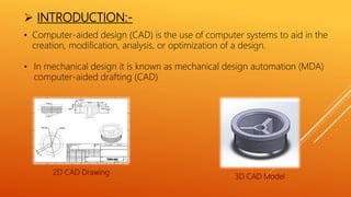
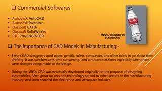
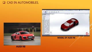
A Presentation on
C.A.D (Solidworks)
SUNRISE GROUP OF INSTITUTIONS,
UDAIPUR
Submitted to:-
Mechanical Dept.
SGI,UDAIPUR
Submitted by:-
Mohd. Shoaib
4th year(M.E.)
CONTENTS
 INTRODUCTION:-
• Commercial Software
• The Importance of CAD Models in Manufacturing:-
• Cad in Automobiles
 DASSAULT SYSTEM: A 3D SOFTWARE COMPANY
 SOLIDWORKS
 MODELING METHOD:-
• Features/Parts
• Command manager
• SolidWorks Features toolbar
 SURFACE MODELING
 SHEET METAL
• Standard Mates
• Mechanical Mates
 DRAWING
 PROJECT 1:- GEAR TRAIN
 PROJECT 2:- SAFETY VALVE
 ASSEMBLY
 INTRODUCTION:-
• Computer-aided design (CAD) is the use of computer systems to aid in the
creation, modification, analysis, or optimization of a design.
• In mechanical design it is known as mechanical design automation (MDA)
computer-aided drafting (CAD)
2D CAD Drawing
3D CAD Model
 Commercial Softwares
 Autodesk AutoCAD
 Autodesk Inventor
 Dassault CATIA
 Dassault SolidWorks
 PTC Pro/ENGINEER
 The Importance of CAD Models in Manufacturing:-
• Before CAD, designers used paper, pencils, rulers, compasses, and other tools to go about their
drafting. It was cumbersome, time consuming, and a nuisance at times especially when there
were changes being made to the design.
• During the 1960s CAD was eventually developed originally for the purpose of designing
automobiles. After great success, the technology spread to other sectors in the manufacturing
industry, and soon reached the electronics and aerospace industry.
MODEL DESIGNED IN
SOLIDWORKS
 CAD IN AUTOMOBILES.
AUDI R8
MODEL OF AUDI R8
 Dassault Systems: 3D Software
Company
• "The 3DEXPERIENCE Company", is a European multinational software company that develops 3D design,
CAD/CAM software.
• Dassault Group created in 1981 by Avions Marcel Dassault to develop a new generation of computer-
aided
• 1997: Dassault Systems acquired SolidWorks, a developer of mechanical design solutions
• Bernard Charlès (President and CEO)
• Total assets €6,311.4 million (end 2015)
• Number of employees:- 13,974
• Website www.3ds.com
 SolidWorks:-
• SOLIDWORKS is a solid modeling computer-
aided design (CAD) computer program.
SolidWorks is published by Dassault Systems.
• SolidWorks Corporation was founded in
December 1993 by Massachusetts Institute of
Technology graduate Jon Hirschtick.
• SolidWorks released its first product
SOLIDWORKS 95, in November 1995.
• According to the publisher, over two million
engineers and designers at more than 165,000
companies were using SolidWorks as of 2013.
The SolidWorks interface
 MODELING METHOD:-
 FEATURES/PARTS
• refers to the building blocks of the part. They are the shapes and operations that
construct the part. Shape-based features typically begin with a 2D or 3D sketch of
shapes such as,holes, slots, etc
• The Sketch consist of geometry such as points, lines,arcs,hyperbola and splines.
3D models parts
 SolidWorks Command Manager
SolidWorks Features toolbar
 Extrude Boss/Base
Command Manager:
The Extrude Boss/base is one of the most frequently used tools in SolidWorks, which enables to convert
a 2D sketch into 3D model. It helps to add material to your sketch files. It is represented by icon
 Revolve boss/base
The revolve feature enables to add materials to your 2D sketch by revolving a long as centerline or axis.
The revolve boss/base is actually rotate the sketch along an axis. It helps to create parts shows the
symmetry like cylinder, sphere, pulleys etc.
 Sweep boss/base
It is sweep feature which sweeps a closed profile through a open or closed path for making solid object.
This feature helps to make solid part by guiding through a definite path.
 Loft
It also helps to add materials between profiles in two directions to create solid object.
 Extrude Cut
Unlike the extrude boss, the Extrude cut removes the material from 3D model by using a
closed sketch (circle or rectangle etc). You can do the cut in one or two directions the
using the property menu.
 Revolved Cut
Using the Revolved Cut, you can remove the material by revolving a closed sketch around an axis.
 Fillet
It creates round internal or external faces by using the edges of the solid model. You can control the
radius of the fillet from the property manager.
 Linear Pattern
If you want to create series of hole in the body of model in linear manner, use Linear Pattern.
 Rib
It adds this walled support to the solid body. You can also do it using the extrude boss, but for
saving the time, Rib options the best.
 Wraps
It helps to create a closed contour on the face of a solid body.
These are the features tools which are contained in the Solidworks Command
manager. These tools help to make solid 3D designs of various shapes or profiles.
 Mirror
If you want to create the mirror of a model, use the Mirror feature.
 Shell
To create thin walled solid box, use the shell feature.
 SURFACE MODELING
• Surfacing is used in CAD and other computer graphics software to describe the skin of a 3D geometric
element, freeform surfacing do not have rigid Radial dimensions, unlike regular surfaces such as planes
cylinders and conic surfaces.
• They are used to describe forms such as turbine blades, card bodies and boat hulls.
 Examples
of surface
modeling
 SURFACE MODEL
 SHEET METAL
• To gain the flexibility to quick and cost-effectively
• Many industries require a wide range of sheet metal parts to house or enclose their design.
 CPU MODEL
 SHEET METAL MECHANISM
 ASSEMBLY
• In an assembly, the analog to sketch relations are mates. Just as sketch relations define
conditions such as tangency, parallelism, and concentricity with respect to sketch geometry,
assembly mates define equivalent relations with respect to the individual parts or
components, allowing the easy construction of assemblies.
• SolidWorks also includes additional
advance mating features such as
gear & cam follower mates.
 ASSEMBLY
 Standard Mates
• In standard mates a relation is given between parts as per
requirements.
• Equivalent relation with respect to the individual parts or
components
 Part 1  Part 2  Part 3
 Assembled model
 STANDARD MATES
 Mechanical Mates
• Mechanical Mates allows model assemblies to
accurately reproduce movement.
 CAM
 HINGE
 GEAR
 RACK AND PINION
 MECHANICAL MATES
 DRAWING
• Drawing can be created either from parts or assemblies. Views are automatically generated from the solid
model, and notes, dimension and tolerances can be easily added to the drawing as needed
• The drawing paper include most paper sizes.
3D models 2D drawing
 PROJECT 1:- GEAR TRAIN & NUT-BOLT
 GEAR TRAIN MECHANISM  GEAR TRAIN MODEL
 NUT & BOLT MECHANISM  NUT & BOLT MODEL
 PROJECT 2:- SAFETY VALVE
 PARTS :-
FIG 1:- BODY FIG 2:- COVER FIG 3:- VALVE SEAT
FIG 4:- GLAND
FIG 6:- VALVE
FIG 7:- HAND WHEEL FIG 8:- NUT
FIG 5:- VALVE
SPINDLE
 ASSEMBLLED VALVE
 MECHANISM OF VALVE
 3D MODEL OF VALVE
 2D SKETCH OF VALVE
ANY QUESTION?

Solidworks_ppt.pptx

  • 1.
    A Presentation on C.A.D(Solidworks) SUNRISE GROUP OF INSTITUTIONS, UDAIPUR Submitted to:- Mechanical Dept. SGI,UDAIPUR Submitted by:- Mohd. Shoaib 4th year(M.E.)
  • 2.
    CONTENTS  INTRODUCTION:- • CommercialSoftware • The Importance of CAD Models in Manufacturing:- • Cad in Automobiles  DASSAULT SYSTEM: A 3D SOFTWARE COMPANY  SOLIDWORKS  MODELING METHOD:- • Features/Parts • Command manager • SolidWorks Features toolbar  SURFACE MODELING  SHEET METAL • Standard Mates • Mechanical Mates  DRAWING  PROJECT 1:- GEAR TRAIN  PROJECT 2:- SAFETY VALVE  ASSEMBLY
  • 3.
     INTRODUCTION:- • Computer-aideddesign (CAD) is the use of computer systems to aid in the creation, modification, analysis, or optimization of a design. • In mechanical design it is known as mechanical design automation (MDA) computer-aided drafting (CAD) 2D CAD Drawing 3D CAD Model
  • 4.
     Commercial Softwares Autodesk AutoCAD  Autodesk Inventor  Dassault CATIA  Dassault SolidWorks  PTC Pro/ENGINEER  The Importance of CAD Models in Manufacturing:- • Before CAD, designers used paper, pencils, rulers, compasses, and other tools to go about their drafting. It was cumbersome, time consuming, and a nuisance at times especially when there were changes being made to the design. • During the 1960s CAD was eventually developed originally for the purpose of designing automobiles. After great success, the technology spread to other sectors in the manufacturing industry, and soon reached the electronics and aerospace industry. MODEL DESIGNED IN SOLIDWORKS
  • 5.
     CAD INAUTOMOBILES. AUDI R8 MODEL OF AUDI R8
  • 6.
     Dassault Systems:3D Software Company • "The 3DEXPERIENCE Company", is a European multinational software company that develops 3D design, CAD/CAM software. • Dassault Group created in 1981 by Avions Marcel Dassault to develop a new generation of computer- aided • 1997: Dassault Systems acquired SolidWorks, a developer of mechanical design solutions • Bernard Charlès (President and CEO) • Total assets €6,311.4 million (end 2015) • Number of employees:- 13,974 • Website www.3ds.com
  • 7.
     SolidWorks:- • SOLIDWORKSis a solid modeling computer- aided design (CAD) computer program. SolidWorks is published by Dassault Systems. • SolidWorks Corporation was founded in December 1993 by Massachusetts Institute of Technology graduate Jon Hirschtick. • SolidWorks released its first product SOLIDWORKS 95, in November 1995. • According to the publisher, over two million engineers and designers at more than 165,000 companies were using SolidWorks as of 2013. The SolidWorks interface
  • 8.
     MODELING METHOD:- FEATURES/PARTS • refers to the building blocks of the part. They are the shapes and operations that construct the part. Shape-based features typically begin with a 2D or 3D sketch of shapes such as,holes, slots, etc • The Sketch consist of geometry such as points, lines,arcs,hyperbola and splines. 3D models parts
  • 9.
     SolidWorks CommandManager SolidWorks Features toolbar  Extrude Boss/Base Command Manager: The Extrude Boss/base is one of the most frequently used tools in SolidWorks, which enables to convert a 2D sketch into 3D model. It helps to add material to your sketch files. It is represented by icon
  • 10.
     Revolve boss/base Therevolve feature enables to add materials to your 2D sketch by revolving a long as centerline or axis. The revolve boss/base is actually rotate the sketch along an axis. It helps to create parts shows the symmetry like cylinder, sphere, pulleys etc.  Sweep boss/base It is sweep feature which sweeps a closed profile through a open or closed path for making solid object. This feature helps to make solid part by guiding through a definite path.  Loft It also helps to add materials between profiles in two directions to create solid object.  Extrude Cut Unlike the extrude boss, the Extrude cut removes the material from 3D model by using a closed sketch (circle or rectangle etc). You can do the cut in one or two directions the using the property menu.
  • 11.
     Revolved Cut Usingthe Revolved Cut, you can remove the material by revolving a closed sketch around an axis.  Fillet It creates round internal or external faces by using the edges of the solid model. You can control the radius of the fillet from the property manager.  Linear Pattern If you want to create series of hole in the body of model in linear manner, use Linear Pattern.  Rib It adds this walled support to the solid body. You can also do it using the extrude boss, but for saving the time, Rib options the best.
  • 12.
     Wraps It helpsto create a closed contour on the face of a solid body. These are the features tools which are contained in the Solidworks Command manager. These tools help to make solid 3D designs of various shapes or profiles.  Mirror If you want to create the mirror of a model, use the Mirror feature.  Shell To create thin walled solid box, use the shell feature.
  • 13.
     SURFACE MODELING •Surfacing is used in CAD and other computer graphics software to describe the skin of a 3D geometric element, freeform surfacing do not have rigid Radial dimensions, unlike regular surfaces such as planes cylinders and conic surfaces. • They are used to describe forms such as turbine blades, card bodies and boat hulls.  Examples of surface modeling  SURFACE MODEL
  • 14.
     SHEET METAL •To gain the flexibility to quick and cost-effectively • Many industries require a wide range of sheet metal parts to house or enclose their design.  CPU MODEL  SHEET METAL MECHANISM
  • 15.
     ASSEMBLY • Inan assembly, the analog to sketch relations are mates. Just as sketch relations define conditions such as tangency, parallelism, and concentricity with respect to sketch geometry, assembly mates define equivalent relations with respect to the individual parts or components, allowing the easy construction of assemblies. • SolidWorks also includes additional advance mating features such as gear & cam follower mates.  ASSEMBLY
  • 16.
     Standard Mates •In standard mates a relation is given between parts as per requirements. • Equivalent relation with respect to the individual parts or components  Part 1  Part 2  Part 3  Assembled model  STANDARD MATES
  • 17.
     Mechanical Mates •Mechanical Mates allows model assemblies to accurately reproduce movement.  CAM  HINGE  GEAR  RACK AND PINION  MECHANICAL MATES
  • 18.
     DRAWING • Drawingcan be created either from parts or assemblies. Views are automatically generated from the solid model, and notes, dimension and tolerances can be easily added to the drawing as needed • The drawing paper include most paper sizes. 3D models 2D drawing
  • 19.
     PROJECT 1:-GEAR TRAIN & NUT-BOLT  GEAR TRAIN MECHANISM  GEAR TRAIN MODEL  NUT & BOLT MECHANISM  NUT & BOLT MODEL
  • 20.
     PROJECT 2:-SAFETY VALVE  PARTS :- FIG 1:- BODY FIG 2:- COVER FIG 3:- VALVE SEAT FIG 4:- GLAND FIG 6:- VALVE FIG 7:- HAND WHEEL FIG 8:- NUT FIG 5:- VALVE SPINDLE
  • 21.
     ASSEMBLLED VALVE MECHANISM OF VALVE  3D MODEL OF VALVE  2D SKETCH OF VALVE
  • 22.