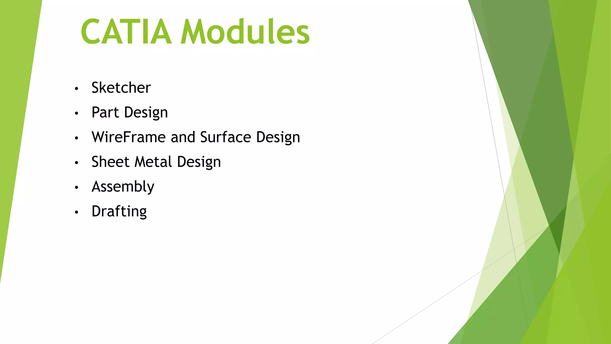
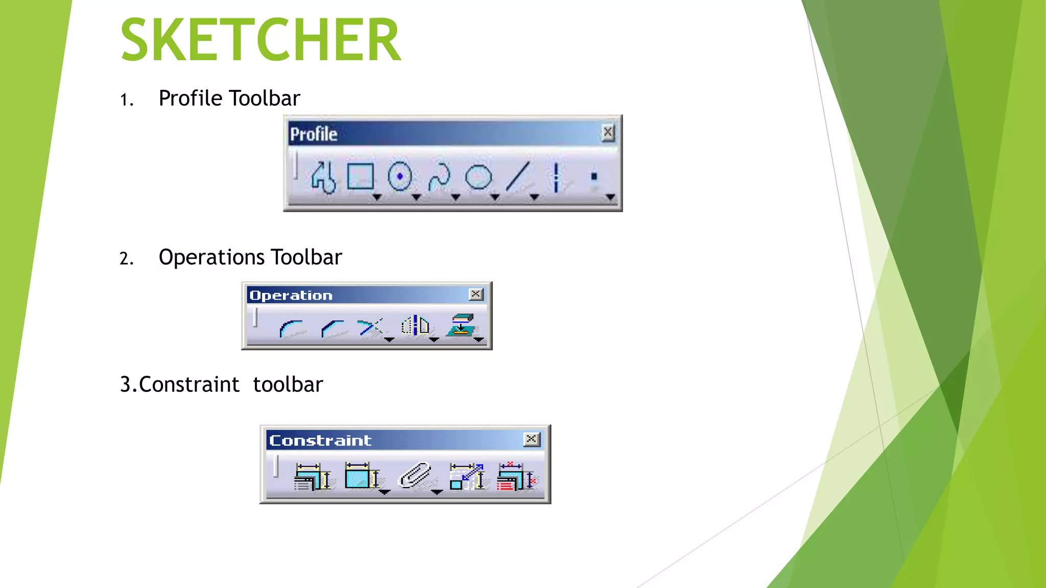
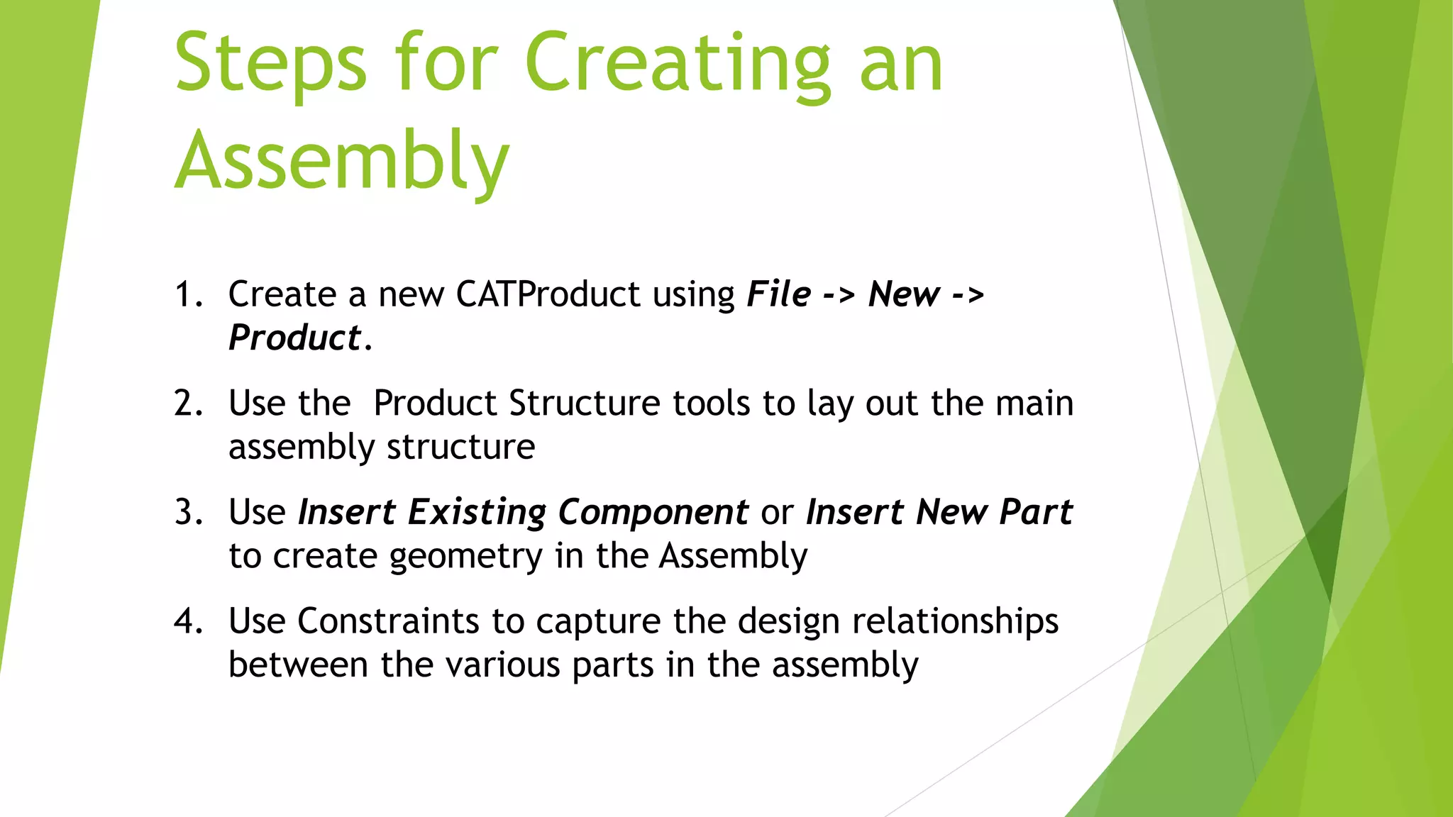
Introduction of CATIA
• Catia is also known as computer aided three
dimensional interactive application. CATIA was
started in 1977 by French Aircraft Manufacturer
Avions Marcel Dassault System .
• It is also used in aerospace, automotive,
shipbuilding, and other industries.
The Specification Tree
• Provides access to the history of how a part was
constructed, and shows the product structure
• Parts can be modified by selecting
them from the spec. tree.
CATIA Modules
• Sketcher
• Part Design
• WireFrame and Surface Design
• Sheet Metal Design
• Assembly
• Drafting
SKETCHER
1. Profile Toolbar
2. Operations Toolbar
3.Constraint toolbar
• The Part Design application is used to create solid
models of parts
• Solid parts are usually created from 2D profiles that
are extruded or revolved to form a base feature
• Parts can be modified by selecting their features in the
specification tree
Part Design
Toolbars in Part Design
1. Sketch-Based Features 2. Dress-Up Features
 Pocket
 Shaft
 Rib
 Multi-section solid
3. Transformation Features
 Translation
 Rotation
 Mirror
 Pattern
Assembly Design
• The Assembly Design application allows you to
create a product model from a number of separate
parts
• The parts in a product assembly are not joined
together, but assembled as they would be in a
physical assembly
• The product assembly structure is hierarchical and
allows you to model complex product relationships
• Constraints can be applied between the parts in
assembly to define relationships between them
Assembly Design
• Constraints Toolbar
 Coincidence
 Contact
 Offset
 Angular
• Product Structure Tools
Insert New Component
Insert New Product
Insert New Part
Insert Existing Component
Replace Component
Steps for Creating an
Assembly
1. Create a new CATProduct using File -> New ->
Product.
2. Use the Product Structure tools to lay out the main
assembly structure
3. Use Insert Existing Component or Insert New Part
to create geometry in the Assembly
4. Use Constraints to capture the design relationships
between the various parts in the assembly
Wireframe and Surface
• Wireframe Toolbar
 Create Point
 Create Line
 Create Plane
 Create Projections
• Surface Toolbar
 Extrude Surfaces
 Surface of Revolution
 Offset Surface
 Sweep Surface
 Create Filling Surface
Wireframe and Surface
• Operations Toolbar
 Join
 Split, Trim
 Transform
• Transformations Toolbar
 Translate
 Rotate
 Create Symmetry
 Scale
Assembly
 Plummer Block
View and dimension of
casting
Base
1
Base
1
Cap
1
2
Nut, Bolt, Lock nut
1.
2. 3.
Brasses
1
THANK YOU

Ppt on catia

  • 1.
    Introduction of CATIA •Catia is also known as computer aided three dimensional interactive application. CATIA was started in 1977 by French Aircraft Manufacturer Avions Marcel Dassault System . • It is also used in aerospace, automotive, shipbuilding, and other industries.
  • 2.
    The Specification Tree •Provides access to the history of how a part was constructed, and shows the product structure • Parts can be modified by selecting them from the spec. tree.
  • 3.
    CATIA Modules • Sketcher •Part Design • WireFrame and Surface Design • Sheet Metal Design • Assembly • Drafting
  • 4.
    SKETCHER 1. Profile Toolbar 2.Operations Toolbar 3.Constraint toolbar
  • 5.
    • The PartDesign application is used to create solid models of parts • Solid parts are usually created from 2D profiles that are extruded or revolved to form a base feature • Parts can be modified by selecting their features in the specification tree Part Design
  • 6.
    Toolbars in PartDesign 1. Sketch-Based Features 2. Dress-Up Features  Pocket  Shaft  Rib  Multi-section solid
  • 7.
    3. Transformation Features Translation  Rotation  Mirror  Pattern
  • 8.
    Assembly Design • TheAssembly Design application allows you to create a product model from a number of separate parts • The parts in a product assembly are not joined together, but assembled as they would be in a physical assembly • The product assembly structure is hierarchical and allows you to model complex product relationships • Constraints can be applied between the parts in assembly to define relationships between them
  • 9.
    Assembly Design • ConstraintsToolbar  Coincidence  Contact  Offset  Angular • Product Structure Tools Insert New Component Insert New Product Insert New Part Insert Existing Component Replace Component
  • 10.
    Steps for Creatingan Assembly 1. Create a new CATProduct using File -> New -> Product. 2. Use the Product Structure tools to lay out the main assembly structure 3. Use Insert Existing Component or Insert New Part to create geometry in the Assembly 4. Use Constraints to capture the design relationships between the various parts in the assembly
  • 11.
    Wireframe and Surface •Wireframe Toolbar  Create Point  Create Line  Create Plane  Create Projections • Surface Toolbar  Extrude Surfaces  Surface of Revolution  Offset Surface  Sweep Surface  Create Filling Surface
  • 12.
    Wireframe and Surface •Operations Toolbar  Join  Split, Trim  Transform • Transformations Toolbar  Translate  Rotate  Create Symmetry  Scale
  • 13.
  • 14.
  • 15.
  • 16.
  • 17.
  • 18.
    Nut, Bolt, Locknut 1. 2. 3.
  • 19.
  • 20.