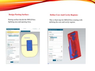
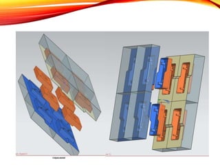
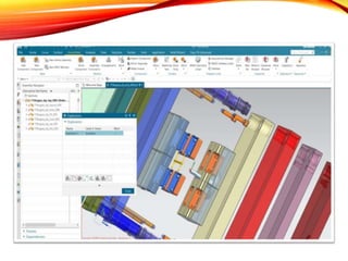
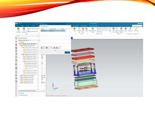
NX is one of the world’s most advanced and tightly integrated CAD/CAM/CAE product development solutions. Spanning the entire range of product development, NX delivers immense value to enterprises of all sizes. It simplifies complex product designs, thus speeding up the process of introducing products to the market.
CADMAXX solutions is the ISO 9001:2008, Certified CAD/CAM/CAE Training Centre, We offered High end Courses are Solidworks, AutoCAD, Catia, UG NX, Pro E, Hypermesn, In Bangalore, Gulbarga, Raichur...
Contact us @ 9739866634
www.cadmaxx.com
Mail: digitalm@cadmaxx.com
Commonly referred to as a 3D Product Lifecycle Management software suite, CATIA supports multiple stages of product development (CAx), including conceptualization, design (CAD), engineering (CAE) and manufacturing (CAM). CATIA facilitates collaborative engineering across disciplines around its 3D EXPERIENCE platform, including surfacing & shape design, electrical, fluid and electronic systems design, mechanical engineering and systems engineering.
A press tool assembly ppt.
CATIA (an acronym of computer aided three-dimensional interactive application, pronounced /kəˈtiə/) is a multi-platform software suite for computer-aided design (CAD), computer-aided manufacturing (CAM), computer-aided engineering (CAE), PLM and 3D, developed by the French company Dassault Systèmes.
CATIA is an acronym for Computer Aided Three-Dimensional Interactive Application. It is the most proficient, powerful and highly popular CAD i.e. computer aided design software. It is created, developed and owned by Dassault Systemes of France.
ME 312 Mechanical Machine Design is the flagship course of Mechanical Engineering Department at DHA Suffa University. This course is offered every semester by Dr. Bilal Siddiqui every fall. It is pre-requisite for capstone projects.
Learn how to use many of the features in Autodesk Fusion 360 in just a few hours. In this course, you will be walked through the design of a lamp using both the modeling and sculpting environment, as well as learning to create photorealistic renderings of your model.
O Siemens NX é o software CAD mais importante para a indústria automobilística da atualidade e fornece pacotes poderosos e bem dimensionados para cada tipo de trabalho que o sistemas necessitam para atender as montadoras.
Conheça aqui os 3 pacotes dimensionados para atender a cada Tier da Indústria Automobilística.
Veja aqui as capacidades do NX para desenvolvimento de produto, partindo do desenho conceito, passando pelo projeto, analise e manufatura do produto, assim como a programação da inspeção de qualidade. Todo o ciclo em único produto!
SOLIDWORKS Premium 2016 gives you powerful, easy-to-use
functionality that automates tasks, streamlines workflows, and
helps you quickly define and validate the form, fit, and function
of your design. Part of the SOLIDWORKS product development
solution—covering design, simulation, sustainability, technical
communication, and data management—SOLIDWORKS Premium
empowers innovative design with specific tools that help you
work more efficiently so you can make better design decisions.
The slide presents introduction to computer aided design and drafting, and introduction to AutoCAD software. 2D and 3D modelling using AutoCAD software is presented.
nanoCAD Platform - a professional-grade DWG CAD softwarenanoCAD India
nanoCAD Platform is a CAD solution fully compatible with professional-grade & industry’s standard DWG support.
New in nanoCAD 23
Batch file processing
Visual styles manager
Materials library
Arc text command
Dimensions
Import of page setups in the batch print
dialog
Bounding prism by selection
UCS by 3D object face
IFC import
3D knot and vertex snaps to spline
Select group command
Inserting an underlay by control points
Highlighting external references in a
drawing
New commands in the external references
dialog box
A course plan of CAD and CAE showing software familiarity of AUTOCAD, SOLIDWORKS, ANSYS, CATIA. The requirement of upskilling for mechanical engineering.
This lesson includes activities for illustrating concepts related to materials selection for laser cutter use. Commonly used materials and their expected behaviors are discussed. We also discuss why some materials are unsafe or unsuitable for laser cutting
Safe Materials
The materials that the laser can cut, are materials like wood, paper, cork, and some kinds of plastics.
Etching can be done on almost anything, wood, cardboard, aluminum, stainless steel, plastic, marble, stone, tile, and glass.
Manufacturing cost is the sum of costs of all resources consumed in the process of making a product. The manufacturing cost is classified into three categories: direct materials cost, direct labor cost and manufacturing overhead.
3D printing is a very popular form of manufacturing, used to create objects from digital designs, by layering resin to build a 3D component. ... To simply answer the question “Why is it called additive manufacturing?”, it is because the build process adds instead of subtracts raw material
Additive manufacturing 3D Printing technologySTAY CURIOUS
Additive manufacturing 3D Printing
3D printing is the process of building an object one thin layer at a time. It is fundamentally additive rather than subtractive in nature. To many, 3D printing is the singular production of often-ornate objects on a desktop printer.
Design of Stage Progressive Die for a Sheet Metal Component STAY CURIOUS
Progressive die stamping is a metal forming process widely used to produce parts for various industries, such as automotive, electronics and appliances. Progressive die stamping consists of several individual work stations, each of which performs one or more different operations on the part.
Computer Numerical Control (CNC) & Manufacturing AutomationSTAY CURIOUS
Manufacturing automation. Automated manufacturing systems operate in the factory on the physical product. They perform operations such as processing, assembly, inspection, or material handling, in some cases accomplishing more than one of these operations in the same system.
Computer Numerical Control (CNC) Machining is the process through which computers control machine-based processes in manufacturing. The kinds of machines controlled include lathes, mills, routers and grinders – all used for manufacturing of metal and plastic products.
Non-traditional machining, also known as “non-conventional machining” or “modern machining method”, generally refers to the machining method of removing or adding materials with energy of electricity, heat energy, light energy, electrochemical energy, chemical energy, sound energy and special mechanical energy,
AutoCAD LT 2D CAD software is the perfect solution for designers and drafters who want an easy-to-use tool for creating drawings faster and with more precision. Cost-effective 2D CAD software for drafting, drawing and documentation. Cost-effective 2D CAD software for drafting, drawing and documentation.
A gear bearing is a type of rolling-element bearing similar to an epicyclic gear. Gear bearings consist of a number of smaller 'satellite' gears which revolve around the center of the bearing along a track on the outsides of the internal and satellite gears, and on the inside of the external gear.
Suspension is the system of tires, tire air, springs, shock absorbers and linkages that connects a vehicle to its wheels and allows relative motion between the two. Suspension systems must support both road holding/handling and ride quality, which are at odds with each other.
A brake system is designed to slow and halt the motion of vehicle. To do this, various components within the brake system must convert vehicle's moving energy into heat. This is done by using friction. Friction is the resistance to movement exerted by two objects on each other.
A 2 stroke engine uses regular gasoline to which you add a small amount of oil. You can run a 4 stroke motor with fuel youve mixed for a 2 stroke. You may have oil smoke from the exhaust or foul plugs over some time, but it wont hurt the engine. You cannot run diesel fuel in a gas engine or vice versa either.
We’ve all been there: You’re driving along the freeway, enjoying the views, and all of a sudden, you hear a beep—you look down, and a symbol appears on your dashboard. You start to wonder what could be wrong.
Some symbols on your car’s dashboard are more obvious than others. However, it’s important to know exactly what they mean in case you need to pull over and call for help. At Virginia Tire & Auto, your safety is our No. 1 priority. That’s why we’re breaking down your dashboard, symbol by symbol.We’ve all been there: You’re driving along the freeway, enjoying the views, and all of a sudden, you hear a beep—you look down, and a symbol appears on your dashboard. You start to wonder what could be wrong.
Some symbols on your car’s dashboard are more obvious than others. However, it’s important to know exactly what they mean in case you need to pull over and call for help. At Virginia Tire & Auto, your safety is our No. 1 priority. That’s why we’re breaking down your dashboard, symbol by symbol.
Turbojets can be highly efficient for supersonic aircraft. Turbojets have poor efficiency at low vehicle speeds, which limits their usefulness in vehicles other than aircraft. Turbojet engines have been used in isolated cases to power vehicles other than aircraft, typically for attempts on land speed records.
Suspension is the system of tires, tire air, springs, shock absorbers and linkages that connects a vehicle to its wheels and allows relative motion between the two. Suspension systems must support both road holding/handling and ride quality, which are at odds with each other.
Welding is a fabrication process that joins materials, usually metals or thermoplastics, by using high heat to melt the parts together and allowing them to cool, causing fusion. Welding is distinct from lower temperature metal-joining techniques such as brazing and soldering, which do not melt the base metal.
An automatic transmission uses sensors to determine when it should shift gears, and changes them using internal oil pressure. ... On a manual transmission the driver does that by pushing in the clutch pedal, but on an automatic, it's handled by the torque converter.
About
Indigenized remote control interface card suitable for MAFI system CCR equipment. Compatible for IDM8000 CCR. Backplane mounted serial and TCP/Ethernet communication module for CCR remote access. IDM 8000 CCR remote control on serial and TCP protocol.
• Remote control: Parallel or serial interface.
• Compatible with MAFI CCR system.
• Compatible with IDM8000 CCR.
• Compatible with Backplane mount serial communication.
• Compatible with commercial and Defence aviation CCR system.
• Remote control system for accessing CCR and allied system over serial or TCP.
• Indigenized local Support/presence in India.
• Easy in configuration using DIP switches.
Technical Specifications
Indigenized remote control interface card suitable for MAFI system CCR equipment. Compatible for IDM8000 CCR. Backplane mounted serial and TCP/Ethernet communication module for CCR remote access. IDM 8000 CCR remote control on serial and TCP protocol.
Key Features
Indigenized remote control interface card suitable for MAFI system CCR equipment. Compatible for IDM8000 CCR. Backplane mounted serial and TCP/Ethernet communication module for CCR remote access. IDM 8000 CCR remote control on serial and TCP protocol.
• Remote control: Parallel or serial interface
• Compatible with MAFI CCR system
• Copatiable with IDM8000 CCR
• Compatible with Backplane mount serial communication.
• Compatible with commercial and Defence aviation CCR system.
• Remote control system for accessing CCR and allied system over serial or TCP.
• Indigenized local Support/presence in India.
Application
• Remote control: Parallel or serial interface.
• Compatible with MAFI CCR system.
• Compatible with IDM8000 CCR.
• Compatible with Backplane mount serial communication.
• Compatible with commercial and Defence aviation CCR system.
• Remote control system for accessing CCR and allied system over serial or TCP.
• Indigenized local Support/presence in India.
• Easy in configuration using DIP switches.
Welcome to WIPAC Monthly the magazine brought to you by the LinkedIn Group Water Industry Process Automation & Control.
In this month's edition, along with this month's industry news to celebrate the 13 years since the group was created we have articles including
A case study of the used of Advanced Process Control at the Wastewater Treatment works at Lleida in Spain
A look back on an article on smart wastewater networks in order to see how the industry has measured up in the interim around the adoption of Digital Transformation in the Water Industry.
CFD Simulation of By-pass Flow in a HRSG module by R&R Consult.pptxR&R Consult
CFD analysis is incredibly effective at solving mysteries and improving the performance of complex systems!
Here's a great example: At a large natural gas-fired power plant, where they use waste heat to generate steam and energy, they were puzzled that their boiler wasn't producing as much steam as expected.
R&R and Tetra Engineering Group Inc. were asked to solve the issue with reduced steam production.
An inspection had shown that a significant amount of hot flue gas was bypassing the boiler tubes, where the heat was supposed to be transferred.
R&R Consult conducted a CFD analysis, which revealed that 6.3% of the flue gas was bypassing the boiler tubes without transferring heat. The analysis also showed that the flue gas was instead being directed along the sides of the boiler and between the modules that were supposed to capture the heat. This was the cause of the reduced performance.
Based on our results, Tetra Engineering installed covering plates to reduce the bypass flow. This improved the boiler's performance and increased electricity production.
It is always satisfying when we can help solve complex challenges like this. Do your systems also need a check-up or optimization? Give us a call!
Work done in cooperation with James Malloy and David Moelling from Tetra Engineering.
More examples of our work https://www.r-r-consult.dk/en/cases-en/
Saudi Arabia stands as a titan in the global energy landscape, renowned for its abundant oil and gas resources. It's the largest exporter of petroleum and holds some of the world's most significant reserves. Let's delve into the top 10 oil and gas projects shaping Saudi Arabia's energy future in 2024.
Sachpazis:Terzaghi Bearing Capacity Estimation in simple terms with Calculati...Dr.Costas Sachpazis
Terzaghi's soil bearing capacity theory, developed by Karl Terzaghi, is a fundamental principle in geotechnical engineering used to determine the bearing capacity of shallow foundations. This theory provides a method to calculate the ultimate bearing capacity of soil, which is the maximum load per unit area that the soil can support without undergoing shear failure. The Calculation HTML Code included.
Final project report on grocery store management system..pdfKamal Acharya
In today’s fast-changing business environment, it’s extremely important to be able to respond to client needs in the most effective and timely manner. If your customers wish to see your business online and have instant access to your products or services.
Online Grocery Store is an e-commerce website, which retails various grocery products. This project allows viewing various products available enables registered users to purchase desired products instantly using Paytm, UPI payment processor (Instant Pay) and also can place order by using Cash on Delivery (Pay Later) option. This project provides an easy access to Administrators and Managers to view orders placed using Pay Later and Instant Pay options.
In order to develop an e-commerce website, a number of Technologies must be studied and understood. These include multi-tiered architecture, server and client-side scripting techniques, implementation technologies, programming language (such as PHP, HTML, CSS, JavaScript) and MySQL relational databases. This is a project with the objective to develop a basic website where a consumer is provided with a shopping cart website and also to know about the technologies used to develop such a website.
This document will discuss each of the underlying technologies to create and implement an e- commerce website.
2. INTRODUCTION TO NX
NX, formerly known as NX Unigraphics or usually just UG, is an
advanced high-end CAD/CAM/CAE software package originally
developed by Unigraphics, but since 2007 by Siemens PLM Software.
It is used, among other tasks, for:
• Design (parametric and direct solid/surface modeling)
• Engineering analysis (static; dynamic; electro-magnetic; thermal,
using the finite element method; and fluid, using the finite volume
method).
• Manufacturing finished design by using included machining
modules.
• NX is a direct competitor to Top Solid, CATIA, Creo, Autodesk
Inventor, and SolidWorks.
3. NX FOR DESIGN: ADVANTAGES AND BENEFITS
Advanced Design Solutions Drive Smarter Decisions
• NX for Design is an integrated solution that helps
you develop innovative new products. With leading-
edge design tools and technologies, NX streamlines
and accelerates the product development process.
Unlike CAD-only solutions and closed enterprise
solutions, NX delivers the highest integration between
development disciplines in an open, collaborative
environment
4. DESIGN ADVANTAGES
Fast, Flexible, Efficient Product Design
• NX design tools are superior in power, versatility and
productivity. You can work faster and more efficiently in the
full range of design tasks, from 2D layout through 3D
modeling, assembly design, drafting and documentation.
Work Seamlessly with Data from Other CAD Systems
• With synchronous technology, NX allows you to directly use
models created with other CAD systems. You can import and
modify CAD geometry from any source with speed, ease and
efficiency. NX is the solution of choice for multi-CAD,
collaborative design
5. DESIGN ADVANTAGES
Power and Capacity for Complex Products
• NX assembly design tools are ready for the most complex assemblies,
even those with thousands of parts. You can create full multi-CAD digital
mockups with NX to quickly identify issues and resolve problems.
Integrated Design Validation
• To help you fulfill customer and engineering requirements, NX offers
integrated, automated design validation capabilities. You can continuously
monitor your designs for compliance with company and industry
standards, and more easily produce designs that achieve your goals and
customer requirements.
Visual Analytics Improve Decision-Making
• With NX visual reporting and analytics, you can instantly gather product
and process information and visualize its impact in the context of the 3D
design. Visual synthesis of PLM data accelerates the design process and
improves decision-making.
6. DESIGN BENEFITS
Reduce Development Time by More than 30 Percent
•With breakthrough technologies, efficient interaction and
streamlined workflows, NX design tools help you
accomplish design tasks much more quickly than with other
CAD systems.
Increase the Number of New Products Introduced Each Year
• By improving design productivity and throughput, NX can
help your engineering teams pursue more opportunities and
develop more products without more resources.
Reduce Delivery Cycle Time by 35 percent
• With integrated design, simulation, tooling and
manufacturing, NX can help you transform and streamline
development processes, using the same knowledge and data
from the first concept to the shop floor.
7. PRODUCT DESIGN
Accelerate Innovation with Leading-Edge 3D Product
Design Software
• The increasing complexity of products, development
processes and design teams challenges you to find new
tools and methods to deliver greater innovation and higher
quality at lower cost. NX 3D product design software from
Siemens PLM Software delivers power, efficiency and cost
savings that extend beyond the design process to all phases
of product development.
9. MODELLING ENVIRONMENT
The Modelling environment is a feature-based environment
in which you can create solid models.
Two dimensional sketching
Advanced Modelling tool
12. ORIENT VIEW
Home key: Orients the current view to Trimetric.
End key: Orients the current view to Isometric.
F8 key: Orients the current view to a selected planar face or datum
plane or the planar view (top, front, right, back, bottom, left) that is
closest to the current view orientation.
View triad
13. COORDINATE SYSTEMS
Absolute Coordinate System
Work Coordinate System
The Absolute Coordinate System is the coordinate
system from which all objects are referenced.
The Work Coordinate System (WCS) is what you will
use for construction when you want to determine
orientations and angles of features. The axes of the WCS
are denoted XC, YC, and ZC. (The “C” stands for
“current”)
14. SKETCHING
Sketching A Sketch is a named set of 2D curves and points located on a
specified plane or path. You can apply rules, in the form of geometric and
dimensional constraints, to establish the criteria your design needs.
Ways to use sketches
20. CONVERT TO/FROM REFERENCE OVERVIEW
Use the Convert To/From Reference command to convert sketch
curves from active to reference, or dimensions from driving to
reference.
28. TYPES OF SWEPT FEATURES
• Extrude – Sweep a section string (1) in a linear direction for a
specified distance.
• Revolve – Rotate a section string (1) around a specified axis (2).
29. • Sweep Along Guide – Sweep a section string (1) along a
guide string (2).
30. BOOLEAN OPERATIONS:
• Unite: The unite command adds the Tool body with the Target
body. For the above example, the output will be as follows if Unite
option is used.
31. • Subtract: When using the subtract option, the Tool body is subtracted from the
Target body. The following would be the output if the rectangle is used as the
Target and the cylinder as the Tool.
• Intersect: This command leaves the volume that is common to both the Target
body and the Tool body. The output is shown below.
32. PATTERN FEATURE
• The Pattern Feature tool is a very versatile tool inNX. This
tool is used to create the linear and circular patterns of
features. It is also used to create the polygon, spiral, along
curve, helix patterns.
34. Surfacing
In NX, surfaces are created in the form of single or multiple patches. With the increase
in patches, the control over the shape of the surface also increases. In NX, surfaces are
known as sheets and surface modelling
Bounded Plane Fill Surface
36. Types of Mesh Surface
Through Curves Through Curve Mesh
N-Sided Surface
Studio Surface
37. Assembly
Assembly is a part file that contains the individual parts. They are added to the part
file in such a way that the parts are virtually in the assembly and linked to the
original part. This eliminates the need for creating separate memory space for the
individual parts in the computer. All the parts are selectable and can be used in the
design process for information and mating to insure a perfect fit as intended by the
designers.
• Touch/Align
• Concentric
• Perpendicular
• Parallel
• Bond
• Angle
• Center
• Distance
38. 3D CAD MODELLING
• NX mechanical design software delivers comprehensive modeling,
enabling you to use the most productive modeling approaches
interchangeably – from explicit solid and surface modeling to
parametric and direct modeling.
39.
40. DRAFTING
The Drafting Application is designed to allow you produce and maintain industry
standard engineering drawings directly from the 3D model or assembly part.
Drawings created in the Drafting application are fully associative to the model
and any changes made to the model are automatically reflected in the drawing.
The Drafting application also offers a set of 2D drawing tools for 2D centric
design and layout requirements
41. Types of views Used in Drafting
Base View - The first view created in a drawing. The
base view is the source for subsequent views and
controls the scale and alignment for them. You can create
one or more base views on a drawing sheet.
Projected View -An orthographic or isometric view that
is generated from a base view or other existing view.
You can create multiple projected views in a single
operation. The position of the cursor relative to the
parent view determines the orientation of the projected
view.
42. Section View - A view created by sketching a line that
defines a plane used to cut through a part or assembly.
You draw the cutting line when you create the view, or
select it from a sketch associated to the parent view
Detail View - An enlarged view of a specified portion
of another drawing view. By default, the scale of the
detail view is double the scale of the parent view, but you
can specify any scale
BOM - Bill of materials or product structure (sometimes bill
of material, BOM or associated list) is a list of the
raw materials, sub-assemblies, intermediate assemblies, sub-
components, parts, and the quantities of each needed to
manufacture an end product
45. Initialize Project
You can use the Initialize Project command to:
a) Create a new MOLD design project.
b) Add additional products to an existing project
to create a family MOLD.
When you create a new project, you can specify:
a) The MOLD units (Inch or Millimetres)
b) The path (folder location) to the project part
files
c) The project name (file name prefix for all
project part files)
d) The material type and shrinkage factor
Part Attributes used for drawings and the Bill of
Materials? A template assembly.
46. Mold CSYS
Shrinkage
MOLD CSYS is used for the correct
orientation and Position Relative to the
MOLD assembly.
Shrinkage is a scale factor applied to a product
model to compensate for part shrinkage while
cooling. Go to Shrinkage:
48. Check Regions:
Analyze the model faces for draft angles, color faces according
to their draft condition find faces that cross over the parting
find undercut faces and edges and split faces.
1.) Go to Check regions
2.) Give direction
3.) Keep existing and calculate
4.) Go to Face check Positive Negative and Vertical draft
face.
5.) Also check crossover face, undercut area and undercuts
edge.
6.) Then go to regions
7.) Set the regions color
8.) Then check the core and cavity region
9.) Click on ok.
49. Patch Surface:
Patch the surface if required its prevent the through
hole of the body
Define Regions:
DEFINE REGIONS is use for define the core and
cavity surface also you can analyse the number of
core and cavity surface.
50. Design Parting Surface:
Parting surface decide the MOLD box
Splitting area and opening Area.
Define Core And Cavity Regions:
This is final step for MOLD box creating with
defining the core and cavity regions
51.
52.
53.
54.
55. PROJECT HIGHLIGHTS
• MINOR GROUP PROJECT
CENTRIFUGAL PUMP
• MAJOR GROUP PROJECT
M1911 A1 Redux
• INDUSTRIAL LIVE WORK