Downloaded 117 times
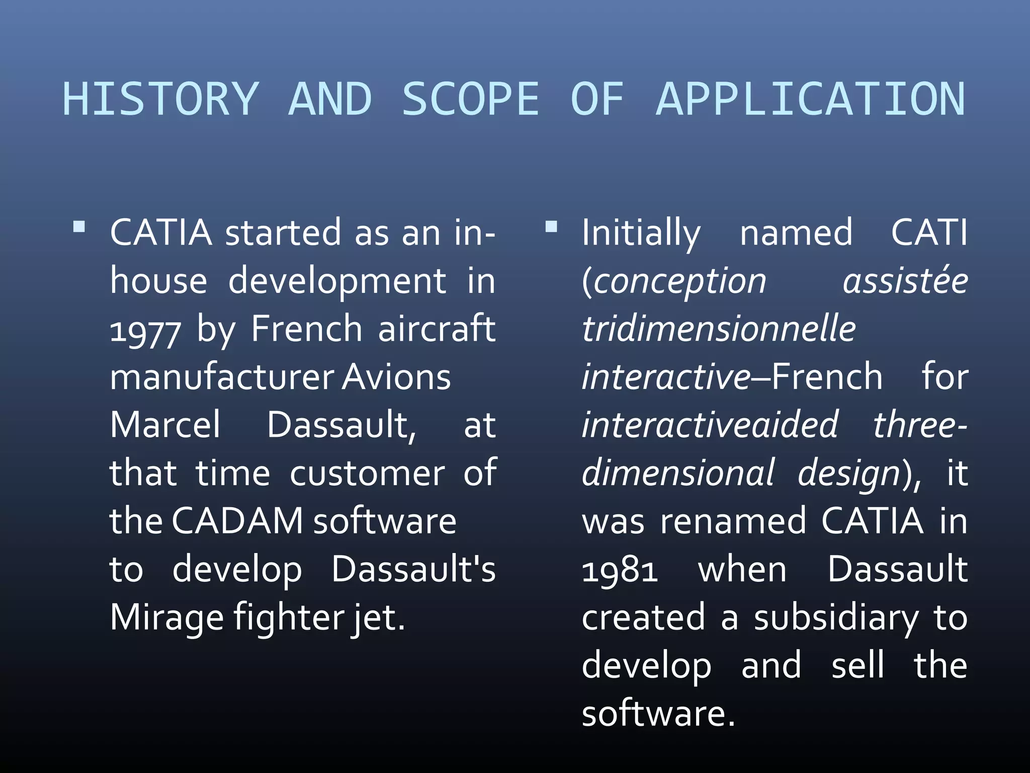
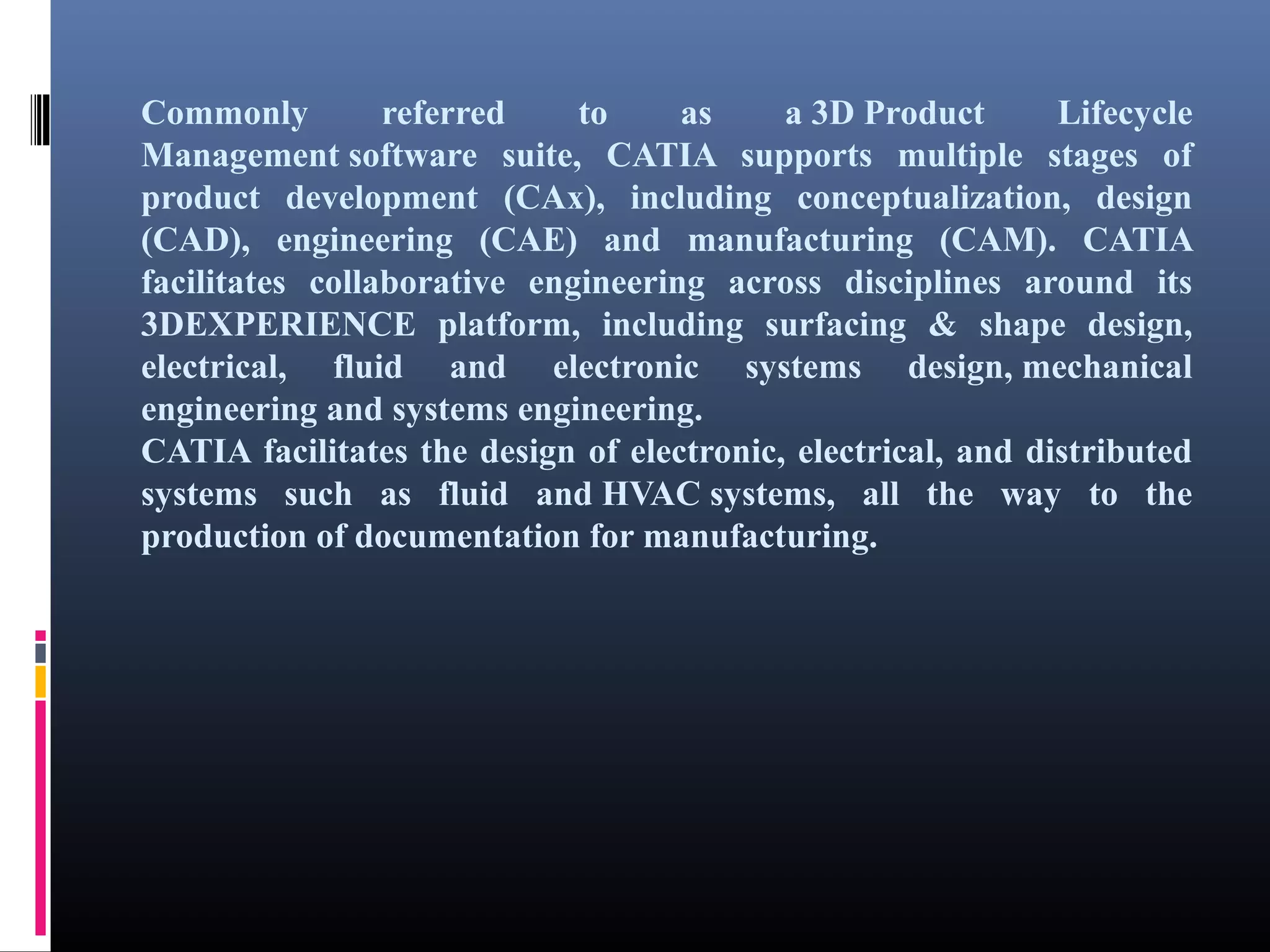
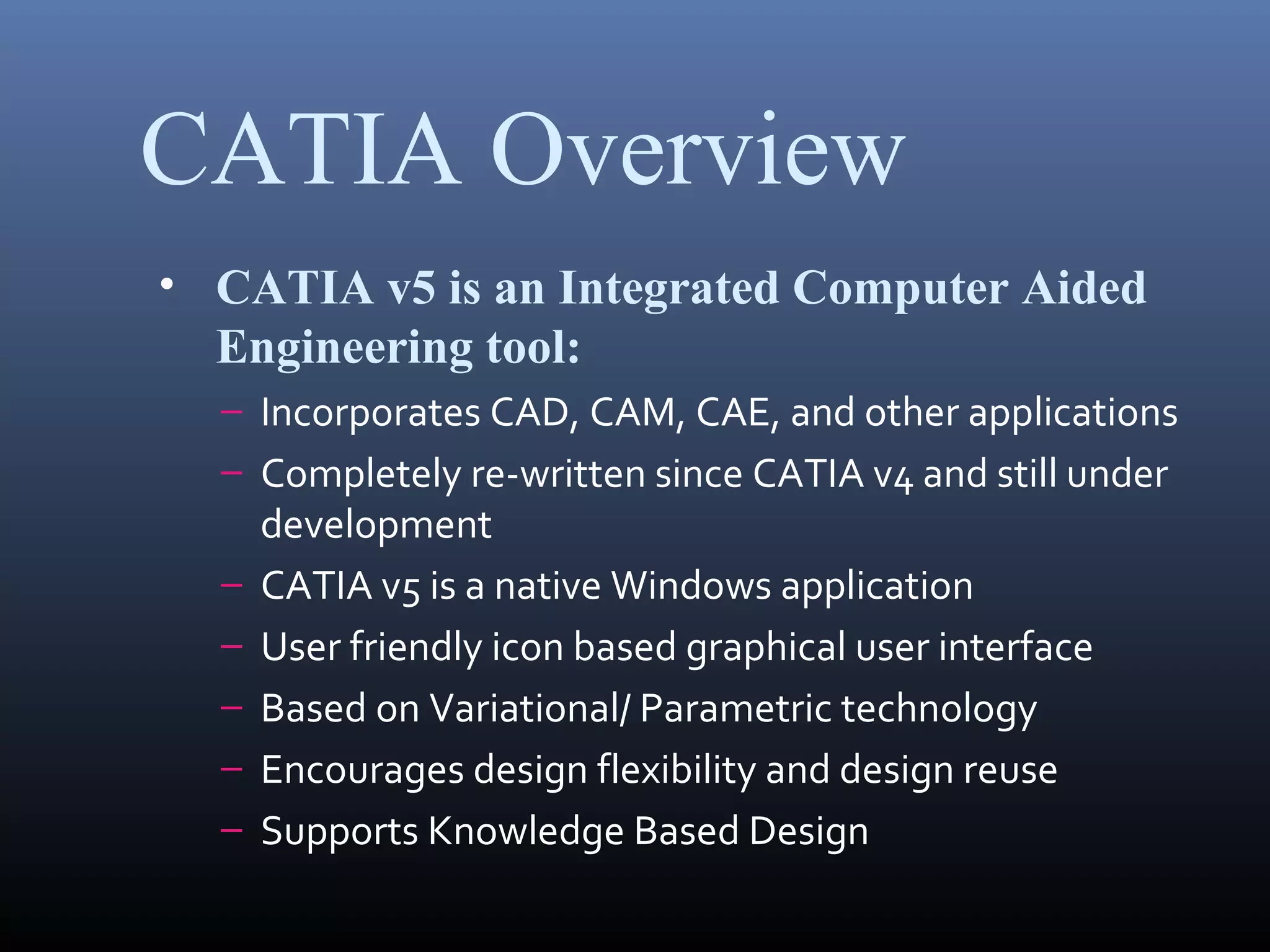
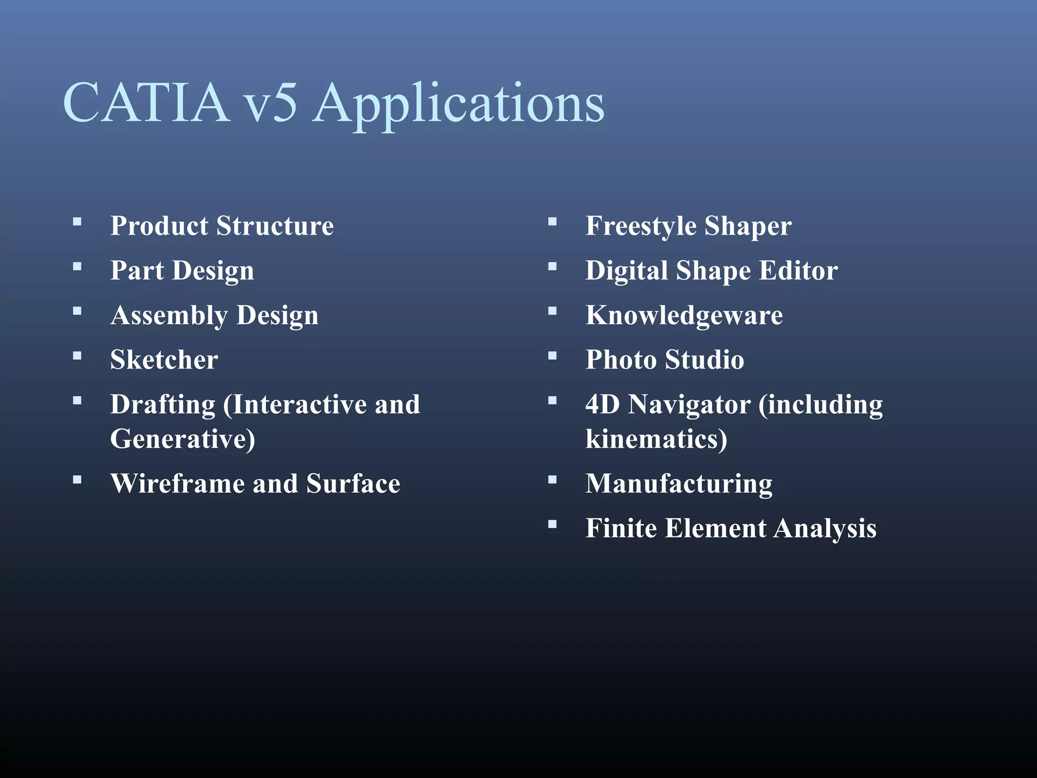


CATIA started as an in-house CAD software developed by Dassault Aviation in 1977. It supports multiple stages of product development including conceptualization, design, engineering, and manufacturing. CATIA facilitates collaborative engineering across disciplines through its 3DEXPERIENCE platform. Key applications within CATIA include part design, assembly design, sketching, drafting, surfacing, finite element analysis, and manufacturing.


