Getting Started with SolidWorks for 3D Product Design
SolidWorks is one of the most widely used computer-aided design (CAD) software applications for creating precise, detailed, and innovative 3D models. This SlideShare presentation serves as a beginner-friendly guide for students, engineers, and designers who want to explore the core features of SolidWorks for product design. Whether you’re creating mechanical components, consumer products, or complex assemblies, this guide will help you start your SolidWorks journey confidently.
📌 What’s Inside?
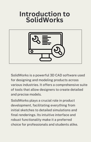
Introduction to SolidWorks and its role in modern design
Understanding the SolidWorks interface and workspace
Essential tools for sketching and part modeling
Creating 2D sketches and converting them into 3D models
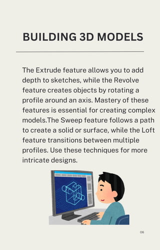
Extrude, revolve, sweep, and loft features explained
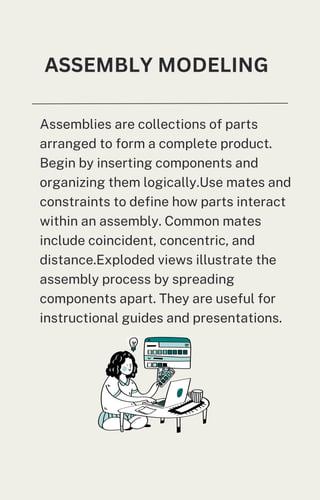
Assembly creation and managing part relationships
Adding materials, textures, and realistic rendering
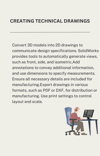
Generating engineering drawings from 3D models
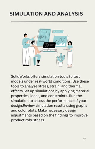
Introduction to simulation tools for stress analysis
Best practices for saving, exporting, and sharing designs
💡 Why This Topic Matters
In today’s fast-paced product development cycle, SolidWorks provides the ability to design, test, and refine products in a virtual environment before physical manufacturing. Learning SolidWorks not only enhances your design skills but also increases your employability in engineering, manufacturing, and industrial design sectors.
📈 Learning Outcomes
By the end of this SlideShare, you will:
Understand the core functionality of SolidWorks
Create 3D parts and assemblies from scratch
Apply basic rendering and visualization techniques
Generate accurate technical drawings
Explore simple simulations for product testing
Follow industry best practices for efficient CAD work
👨🎓 Who Should Read This?
Engineering students and beginners in CAD
Product designers and industrial design learners
Mechanical engineers working on prototyping
Professionals transitioning to 3D design tools
📚 Academic & Professional Relevance
SolidWorks is a valuable skill for academic projects, internships, and industry roles. From student design competitions to advanced product prototyping, mastering SolidWorks opens opportunities in multiple technical fields.


![solidworks1-171128203129[1].pptx](https://cdn.slidesharecdn.com/ss_thumbnails/solidworks1-1711282031291-231012152836-e87ded6f-thumbnail.jpg?width=640&height=640&fit=bounds)


