This document presents a project report for a home automation system called Webcasa. It describes the system's hardware and software requirements. The system will use an Arduino board connected to an Ethernet shield to control appliances and monitor temperature via a web interface. It will allow users to remotely control devices like lights, appliances and check the temperature of rooms in their home from a web browser. The report outlines the project objectives, proposed features, hardware components, software tools and design of the home automation system.


![15
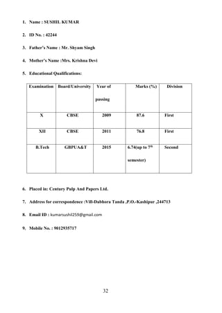
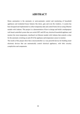
"on" position. In the accompanying schematic diagram, points A and B connect to the coil. Points
C and D connect to the switch. When you apply a voltage across the coil at points A and B, you
create an electromagnetic field, which attracts a lever in the switch, causing it to make or break
contact in the circuit at points C and D (depending if the design is NO or NC). The switch contacts
remain in this state until you remove the voltage to the coil. Relays come in different switch
configurations. The switches may have more than one "pole," or switch contact. The diagram
shows a "single pole single throw" configuration, referred to as SPST. This is similar to a wall
light switch in your home. With a single "throw" of the switch, you close the circuit.
Figure 2.5: The Single Pole Double Throw Relay
A single pole double throw (SPDT) relay configuration switches one common pole to two other
poles, flipping between them. As shown in the schematic diagram, the common point E completes
a circuit with C when the relay coil is at rest, that is, no voltage is applied to it. This circuit is
"closed." A gap between the contacts of point E and D creates an "open" circuit. When you apply
power to the coil, a metal level is pulled down, closing the circuit between points E and D and
opening the circuit between E and C. A single pole double throw relay can be used to alternate
which circuit a voltage or signal will be sent to.
2.4.5 LAN (Local Area Network)
A local area network (LAN) is a computer network that interconnects computers within a limited
area such as a home, school, computer laboratory, or office building, using network media.[1] The](https://image.slidesharecdn.com/b3eb1652-b197-4799-921a-b6e4952e1e84-151209113531-lva1-app6892/85/Project-Report-Webcasa-Final-1-21-320.jpg)


![23
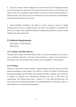
CHAPTER 4 Software Development
#include <SPI.h>
#include <Ethernet.h>
#include <SD.h>
#include <YalerEthernetServer.h>
// size of buffer used to capture HTTP requests
#define REQ_BUF_SZ 60
// MAC address from Ethernet shield sticker under board
byte mac[] = { 0x90, 0xA2, 0xDA, 0x0D, 0x42, 0x3E };
byte ip[] = { 192, 168, 0,111};
EthernetServer server(80);
// IP address, may need to change depending on network
//YalerEthernetServer server("try.yaler.net", 80, "gsiot-ymkn-21xr"); // create a server at port 80
File webFile; // the web page file on the SD card
char HTTP_req[REQ_BUF_SZ] = {0}; // buffered HTTP request stored as null terminated string
char req_index = 0; // index into HTTP_req buffer
boolean LED_state = 0; // stores the states of the LEDs
void setup()
{
// disable Ethernet chip
pinMode(10, OUTPUT);
digitalWrite(10, HIGH);
Serial.begin(9600); // for debugging
// initialize SD card
Serial.println("Initializing SD card...");
if (!SD.begin(4)) {
Serial.println("ERROR - SD card initialization failed!");](https://image.slidesharecdn.com/b3eb1652-b197-4799-921a-b6e4952e1e84-151209113531-lva1-app6892/85/Project-Report-Webcasa-Final-1-29-320.jpg)

![25
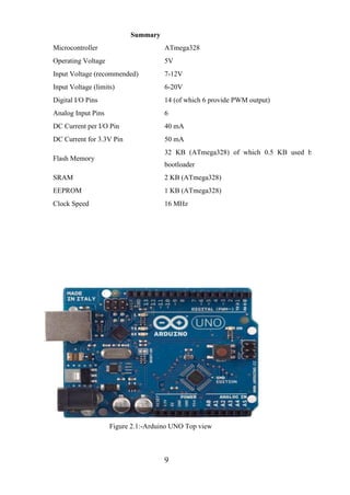
// leave last element in array as 0 to null terminate string (REQ_BUF_SZ - 1)
if (req_index < (REQ_BUF_SZ - 1)) {
HTTP_req[req_index] = c; // save HTTP request character
req_index++;
}
// last line of client request is blank and ends with n
// respond to client only after last line received
if (c == 'n' && currentLineIsBlank) {
// send a standard http response header
client.println("HTTP/1.1 200 OK");
// remainder of header follows below, depending on if
// web page or XML page is requested
// Ajax request - send XML file
if (StrContains(HTTP_req, "ajax_inputs")) {
// send rest of HTTP header
client.println("Content-Type: text/xml");
client.println("Connection: keep-alive");
client.println();
SetLEDs();
// send XML file containing input states
XML_response(client);
} else
{ // web page request
// send rest of HTTP header
client.println("Content-Type: text/html");
client.println("Connection: keep-alive");
client.println();
// send web page
webFile = SD.open("index.htm"); // open web page file
if (webFile) {
while(webFile.available()) {
client.write(webFile.read()); // send web page to client
}](https://image.slidesharecdn.com/b3eb1652-b197-4799-921a-b6e4952e1e84-151209113531-lva1-app6892/85/Project-Report-Webcasa-Final-1-31-320.jpg)


![28
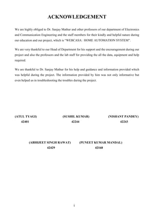
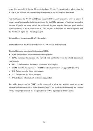
str[i] = 0;
}
}
// searches for the string sfind in the string str
// returns 1 if string found
// returns 0 if string not found
char StrContains(char *str, char *sfind)
{
char found = 0;
char index = 0;
char len;
len = strlen(str);
if (strlen(sfind) > len) {
return 0;
}
while (index < len) {
if (str[index] == sfind[found]) {
found++;
if (strlen(sfind) == found) {
return 1;
}
}
else {
found = 0;
}
index++;
}
return 0;
}](https://image.slidesharecdn.com/b3eb1652-b197-4799-921a-b6e4952e1e84-151209113531-lva1-app6892/85/Project-Report-Webcasa-Final-1-34-320.jpg)