Downloaded 174 times
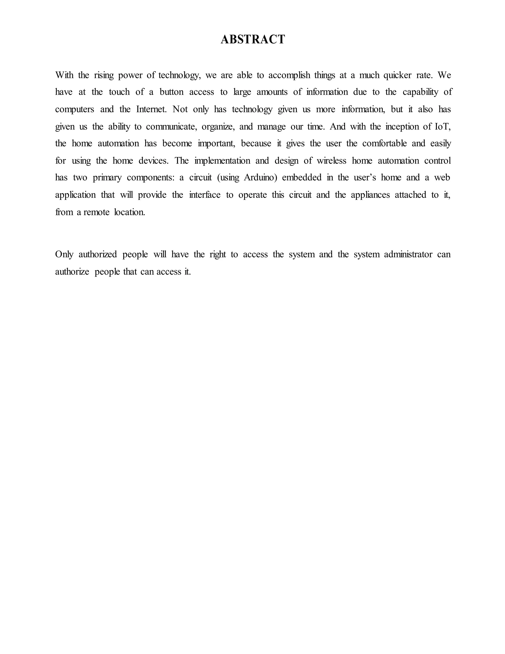


![According to the Cisco Internet Business Solutions Group (IBSG), IoT is simply the point in time
when more “things or objects” were connected to the Internet than people. [1]
In 2003, there were approximately 6.3 billion people living on the planet and 500 million devices
connected to the Internet. [2] By dividing the number of connected devices by the world
population, we find that there was less than one (0.08) device for every person. Based on Cisco
IBSG’s definition, IoT didn’t yet exist in 2003 because the number of connected things was
relatively small given that ubiquitous devices such as smartphones were just being introduced. For
example, Steve Jobs, Apple’s CEO, didn’t unveil the iPhone until January 9, 2007 at the Macworld
conference. [3]
Explosive growth of smartphones and tablet PCs brought the number of devices connected to the
Internet to 12.5 billion in 2010, while the world’s human population increased to 6.8 billion,
making the number of connected devices per person more than 1 (1.84 to be exact) for the first time
in history. [4] By 2015 more than 25 billion devices were connected to the Internet and looking to
the future, Cisco IBSG predicts the statistic will increase to 50 billion by 2020. It is important to
note that these estimates do not take into account rapid advances in Internet or device technology;
the numbers presented are based on what is known to be true today.
Figure 1.1. The Internet of Things Was “Born” Between 2008 and 2009
1.2.3 IOT AS A NETWORK OF NETWORKS
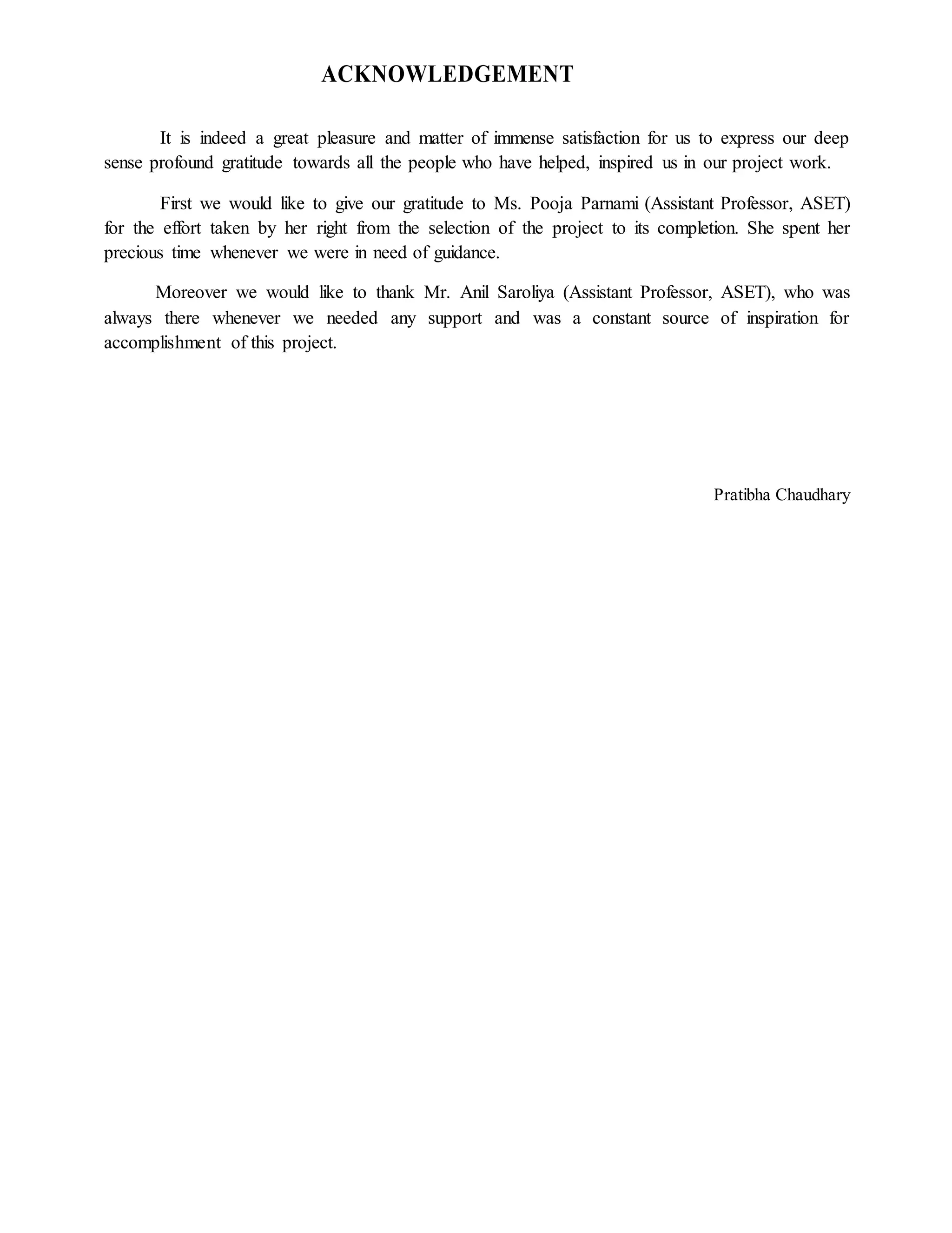
Currently, IoT is made up of a loose collection of disparate, purpose-built networks. Today’s
cars, for example, have multiple networks to control engine function, safety features,
communications systems, and so on. Commercial and residential buildings also have various](https://image.slidesharecdn.com/coverpagepratibha-180712074628/75/IoT-Home-Automation-System-11-2048.jpg)
![control systems for heating, venting, and air conditioning (HVAC); telephone service; security; and
lighting. As IoT evolves, these networks, and many others, will be connected with added security,
analytics, and management capabilities (see Figure 2). This will allow IoT to become even more
powerful in what it can help people achieve.
Figure 1.2. IoT Can Be Viewed as a Network of Networks
1.2.4 WHY IS IOT IMPORTANT?
IoT IS immensely important because it is the first real evolution of the Internet—a leap that will
lead to revolutionary applications that have the potential to dramatically improve the way people
live, learn, work, and entertain themselves. Already, IoT has made the Internet sensory
(temperature, pressure, vibration, light, moisture, stress), allowing us to become more proactive
and less reactive.
In addition, the Internet is expanding into places that until now have been unreachable. Patients are
ingesting Internet devices into their own bodies to help doctors diagnose and determine the causes
of certain diseases. [5] Extremely small sensors can be placed on plants, animals, and geologic
features, and connected to the Internet. [6] At the other end of the spectrum, the Internet is going
into space through Cisco’s Internet Routing in Space (IRIS) program. [7]
1.2.5 IOT: CRITICAL FOR HUMAN PROGRESSION
As the planet’s population continues to increase, it becomes even more important for people to
become stewards of the earth and its resources. In addition, people desire to live healthy, fulfilling,
and comfortable lives for themselves, their families, and those they care about. By combining the
ability of the next evolution of the Internet (IoT) to sense, collect, transmit, analyze, and distribute
data on a massive scale with the way people process information, humanity will have the](https://image.slidesharecdn.com/coverpagepratibha-180712074628/75/IoT-Home-Automation-System-12-2048.jpg)
![knowledge and wisdom it needs not only to survive, but to thrive in the coming months, years,
decades, and centuries.
1.2.6 IOT APPLICATIONS
When we crossed the threshold of connecting more objects than people to the Internet, a huge
window of opportunity opened for the creation of applications in the areas of automation, sensing,
and machine-to-machine communication. In fact, the possibilities are almost endless. The
following examples highlight some of the ways IoT is changing people’s lives for the better.
1.2.7 MUMBAI: A TALE OF TWO CITIES
The amount people from Dharavi pay for municipal-grade water is $1.12 per cubic meter. This
compares to $0.03 for residents of Warden Road. The injustice is clear: the poor people of Mumbai
pay 37 times more for water (a basic human necessity)[8] The main source of the disparity is the
higher cost of delivering utility services to poorer neighbourhoods because of infrastructure
inefficiencies, problems such as leaks, and theft.
IoT, because of its ubiquitous sensors and connected systems, will provide authorities with more
information and control in order to identify and fix these problems. This will allow utilities to
operate more profitably, giving them extra incentive to improve infrastructures in poorer
neighbourhoods. More efficiency will also allow for lower prices, which, in turn, will encourage
those taking services for free to become paying customers. [9]
1.2.8 BETTER QUALITY OF LIFE FOR THE ELDERLY
The world’s population is aging. In fact, approximately 1 billion people age 65 and older will be
classified as having reached “non-working age” by the middle of the century.[10] IoT can
significantly improve quality of life for the surging number of elderly people. For example,
imagine a small, wearable device that can detect a person’s vital signs and send an alert to a
healthcare professional when a certain threshold has been reached, or sense when a person has
fallen down and can’t get up.
1.2.9 CHALLENGES AND BARRIERS TO IOT
Several barriers, however, have the potential to slow the development of IoT. The three largest are
the deployment of IPv6, power for sensors, and agreement on standards.](https://image.slidesharecdn.com/coverpagepratibha-180712074628/75/IoT-Home-Automation-System-13-2048.jpg)
![ DEPLOYMENT OF IPv6: The world ran out of IPv4 addresses in February 2010. While
no real impact has been seen by the general public, this situation has the potential to slow
IoT’s progress since the potentially billions of new sensors will require unique IP addresses.
In addition, IPv6 makes the management of networks easier due to auto configuration
capabilities and offers improved security features.
SENSOR ENERGY: For IoT to reach its full potential, sensors will need to be self-
sustaining. Imagine changing batteries in billions of devices deployed across the planet and
even into space. Obviously, this isn’t possible. What’s needed is a way for sensors to
generate electricity from environmental elements such as vibrations, light, and airflow.[11]
In a significant breakthrough, scientists announced a commercially viable nanogenerator—a
flexible chip that uses body movements such as the pinch of a finger to generate
electricity—at the 241st National Meeting & Exposition of the American Chemical Society
in March 2011.[12]
STANDARDS: While much progress has been made in the area of standards, more is
needed, especially in the areas of security, privacy, architecture, and communications. IEEE
is just one of the organizations working to solve these challenges by ensuring that IPv6
packets can be routed across different network types. It is important to note that while
barriers and challenges exist, they are not insurmountable. Given the benefits of IoT, these
issues will get worked out. It is only a matter of time.
1.3 HOME AUTOMATION SYSTEMS
1.3.1 INTRODUCTION: EVOLUTION OF HOME AUTOMATION SYSTEMS.
The concept of “automation” has existed for many years. It began with a student connecting two
electric wires to the hands of an alarm clock in order to close a circuit of a battery and light bulb.
Later, companies developed automated systems of their own to control alarms, sensors, actuators
and video cameras and, in so doing, created the first automated buildings. The term “intelligent
home” followed. Due to the obvious advantages of these systems, their influence on the
conventional home was predictable and finally, in 1988, the term domotics was coined. “Domotics
is the application of computer and robot technologies to domestic appliances. It is a portmanteau
word formed from domus (Latin, meaning house) and robotics” .[13] A modern definition of
Domotics could be the interaction of technologies and services applied to different buildings with
the purpose of increasing security, comfort, communications and energy savings (Moraes et al.,
2000).](https://image.slidesharecdn.com/coverpagepratibha-180712074628/75/IoT-Home-Automation-System-14-2048.jpg)
![control panel of a security system, and a user-friendly app interface that can be accessed via an
Internet-enabled PC, Smartphone or tablet.
1.3.2.4 ENERGY EFFICIENCY
One clear advantage of home automation is the unmatched potential for energy savings, and
therefore cost savings. Your thermostat is already "smart" in the sense that it uses a temperature
threshold to govern the home's heating and cooling system. In most cases, thermostats can also be
programmed with different target temperatures in order to keep energy usage at a minimum during
the hours when you're least likely to benefit from the heating and cooling.
1.3.3 POTENTIAL RISKS AND LIMITATIONS
Many home automation devices rely on external dependencies. For example, in 2016 the "Revolv
Hub" promised a "Lifetime Subscription" which depended on servers that Google took ownership
of in 2014 and decided to shut down permanently. This left their users with a bricked device. [14]
Other examples include remotely disabled privacy settings on Android smartphones, removed
ability to run GNU/Linux on a Playstation 3, remotely re-enforced EULA on Wii U etc. [15]
Another aspect is that owners that bought their device are not free to point their devices at a
different server, or collaborate on improved software. As such action violates the United
States DMCA section 1201, which however in 2015 got an exemption for "local use" or in local
networks. These force tinkerers into a legal grey area if they want to make their device work. [15]
The Electronic Frontier Foundation thinks buyers should refuse electronics and software that
prioritize the manufacturer's wishes above their own. [15]
RISKS: Often IoT devices lack stringent security measures; some attacks are already
capable of exploiting vulnerabilities in Linux-based IoT systems and routers. Sometimes
attackers come in over the bridge from traditional IT systems into "operational" technology
(OT) or IoT systems like the blast furnace or factory floor operations, or the networks
supporting ATM or POS operations. Sometimes they dial-up cellular modems on these IoT
devices, and other times they attack them directly over the Internet. [16]
LIMITATIONS: Some limitations of home automation include the high cost of ownership,
inflexibility of interconnected devices, and poor manageability. [17]
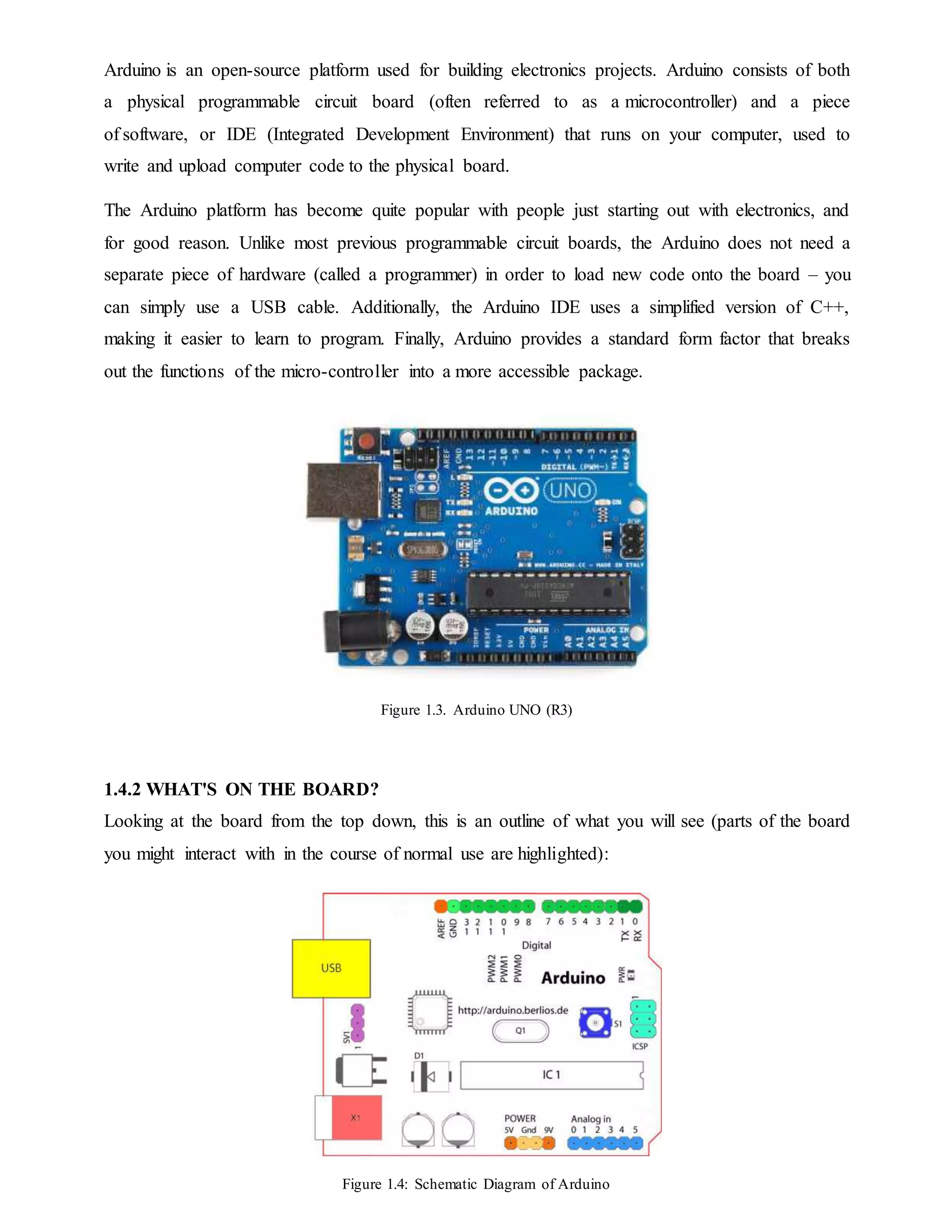
1.4 ARDUINO
1.4.1 INTRODUCTION](https://image.slidesharecdn.com/coverpagepratibha-180712074628/75/IoT-Home-Automation-System-17-2048.jpg)


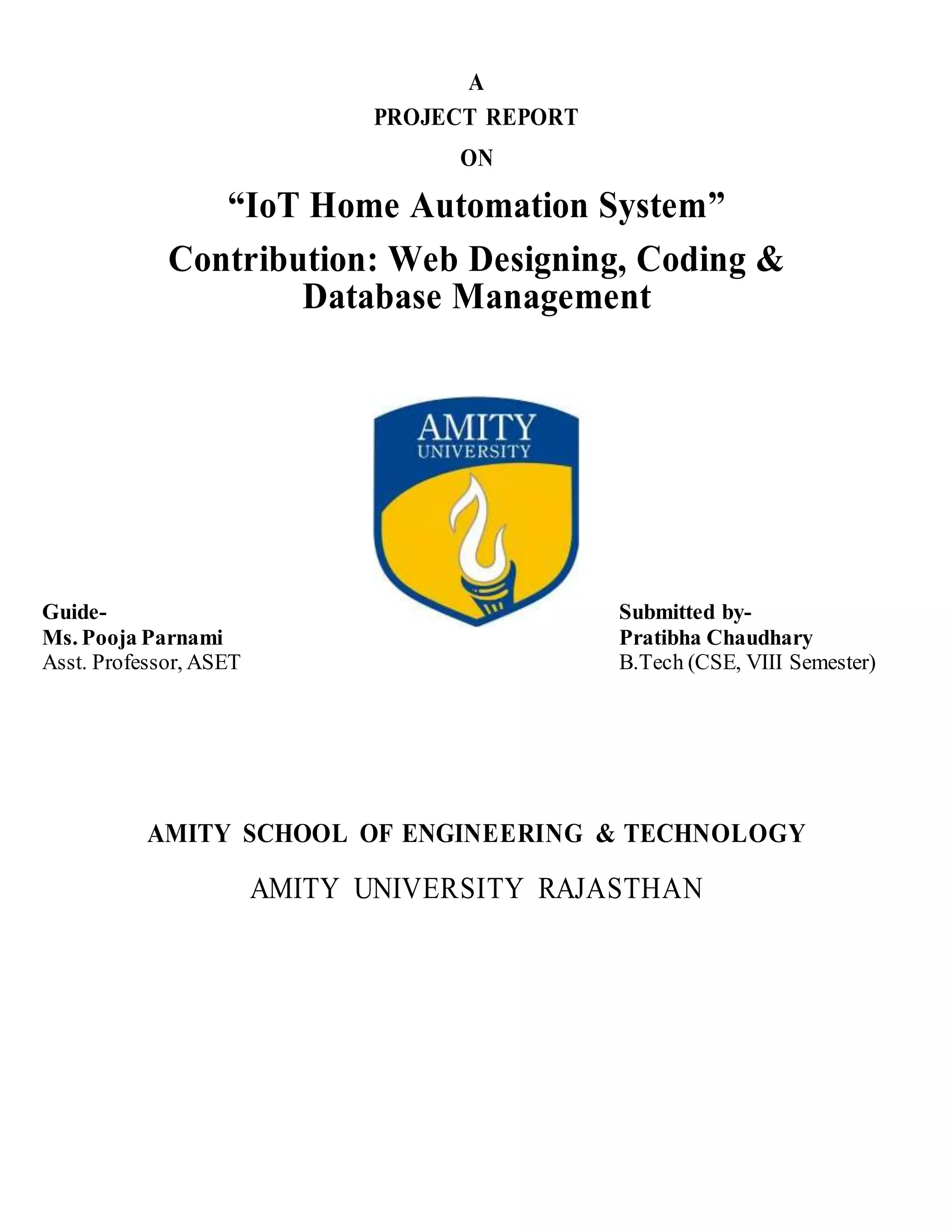
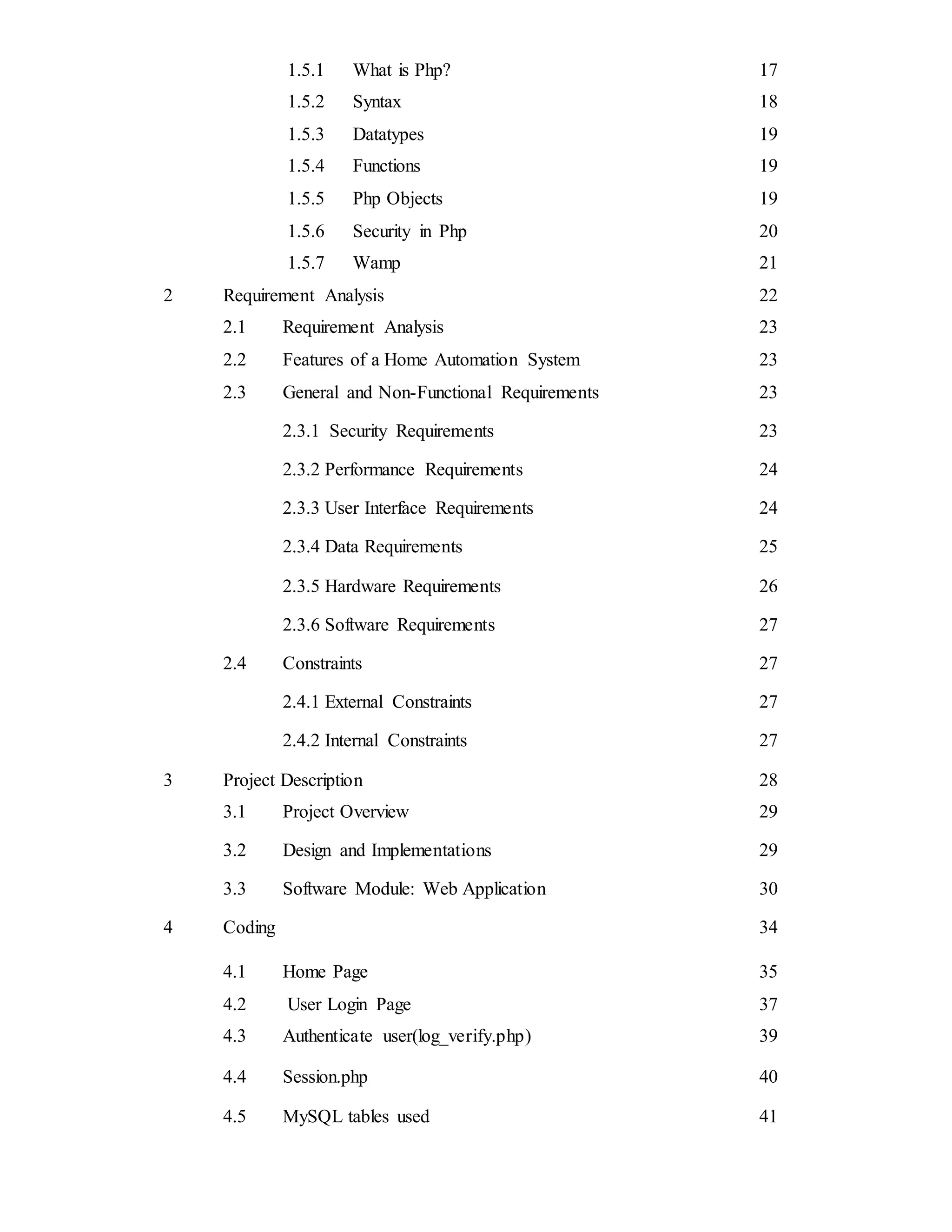
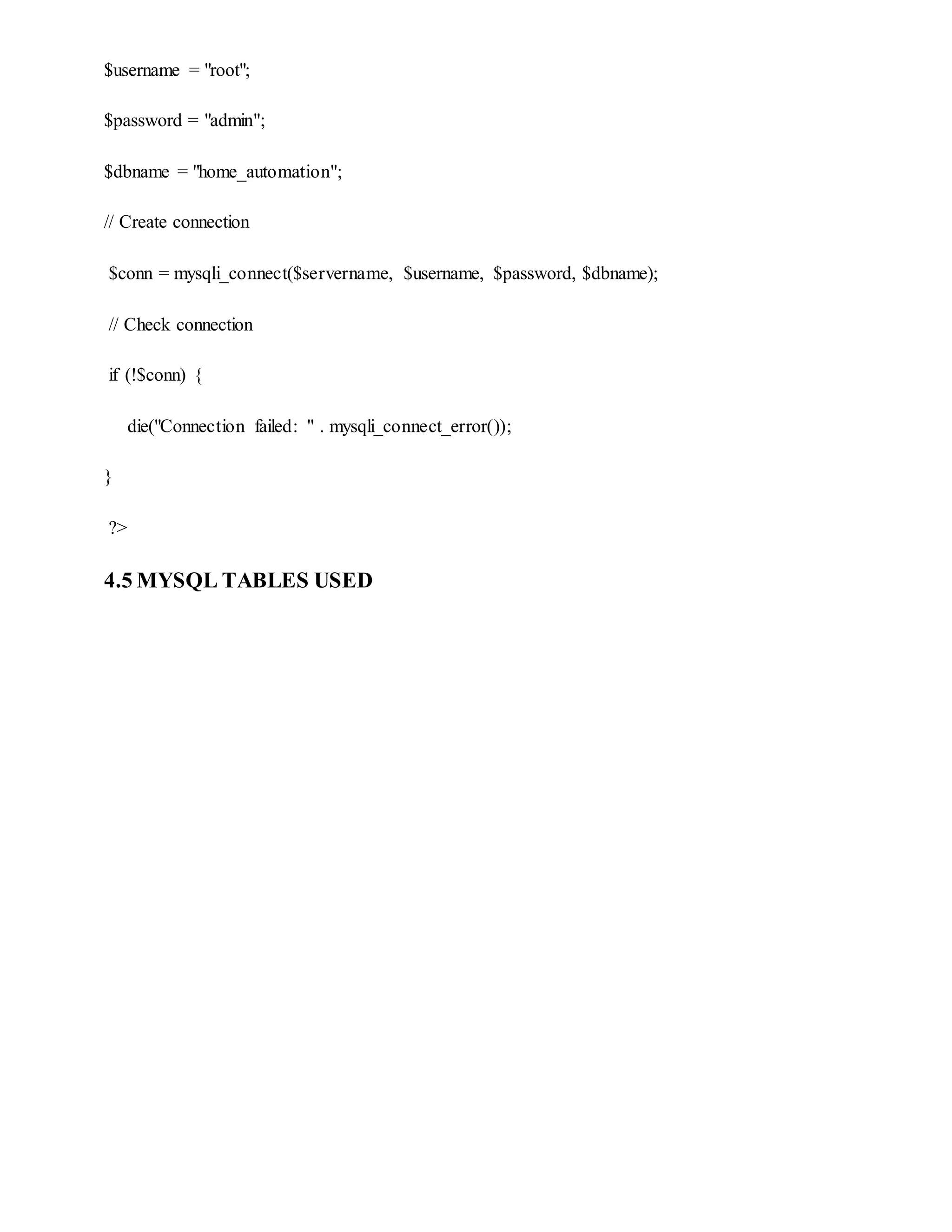
![4.3 AUTHENTICATE USER (User_Verify.Php)
<?php
include "session.php";
$uname=$_POST['uname'];
$pswd=$_POST['pswd'];
$sql = "SELECT * FROM UserKey WHERE UserName = '$uname'";
$result = mysqli_query($conn,$sql);
$row = mysqli_fetch_array($result);
$_SESSION['unikey'] = $row['UniKey'];
$sql="select * from user where username='$uname'&& password='$pswd' ";
$result = mysqli_query($conn,$sql);
$row=mysqli_fetch_array($result);
if($row['password']==$pswd && $row['username']==$uname)
{
$_SESSION['username']=$uname;
$_SESSION['password']=$pswd;
header("location:controlpanel_device.php");
}
else
{
header("location:user_login.php");
}
?>
4.4 Session.php
<?php
session_start();
$servername = "localhost";](https://image.slidesharecdn.com/coverpagepratibha-180712074628/75/IoT-Home-Automation-System-45-2048.jpg)


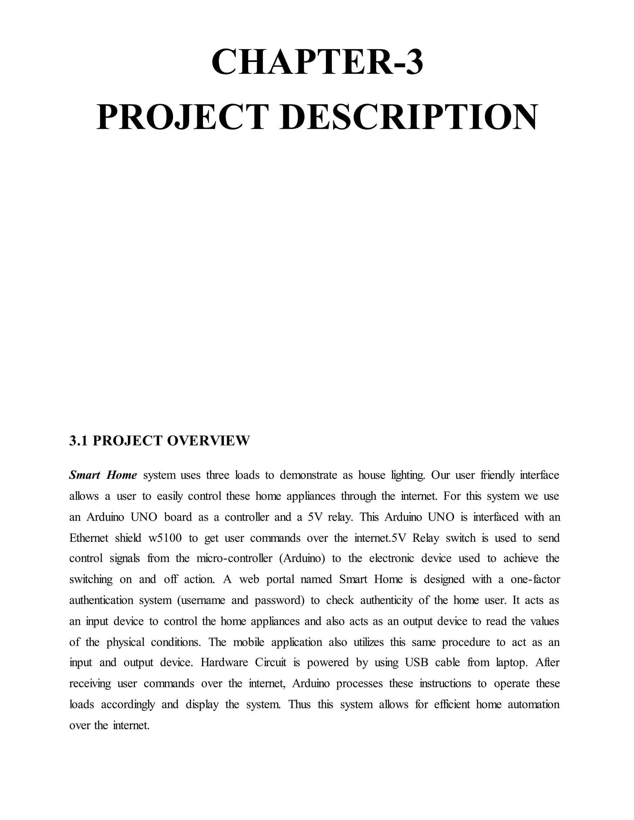
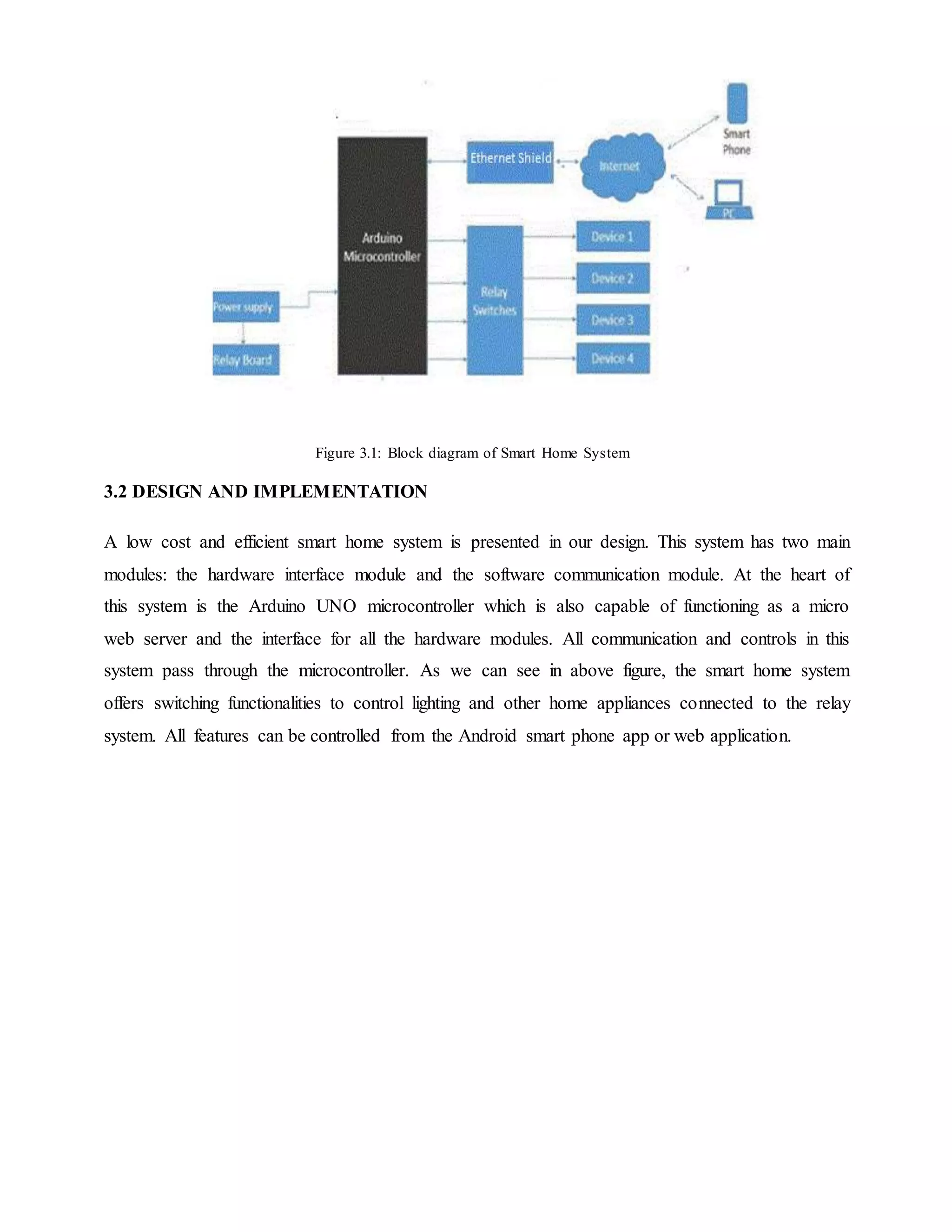
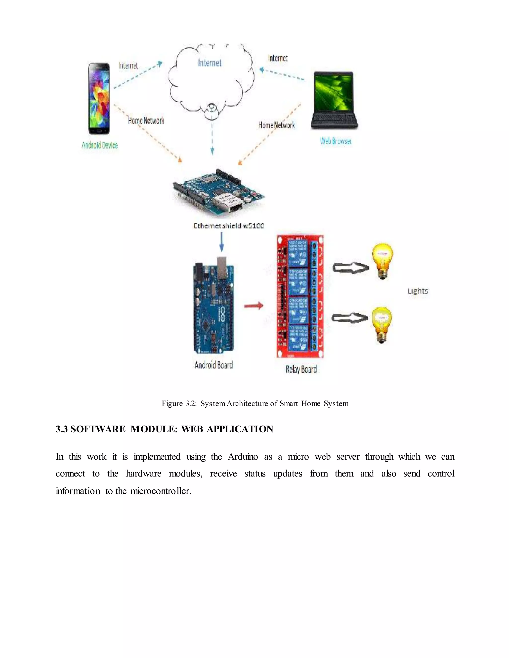
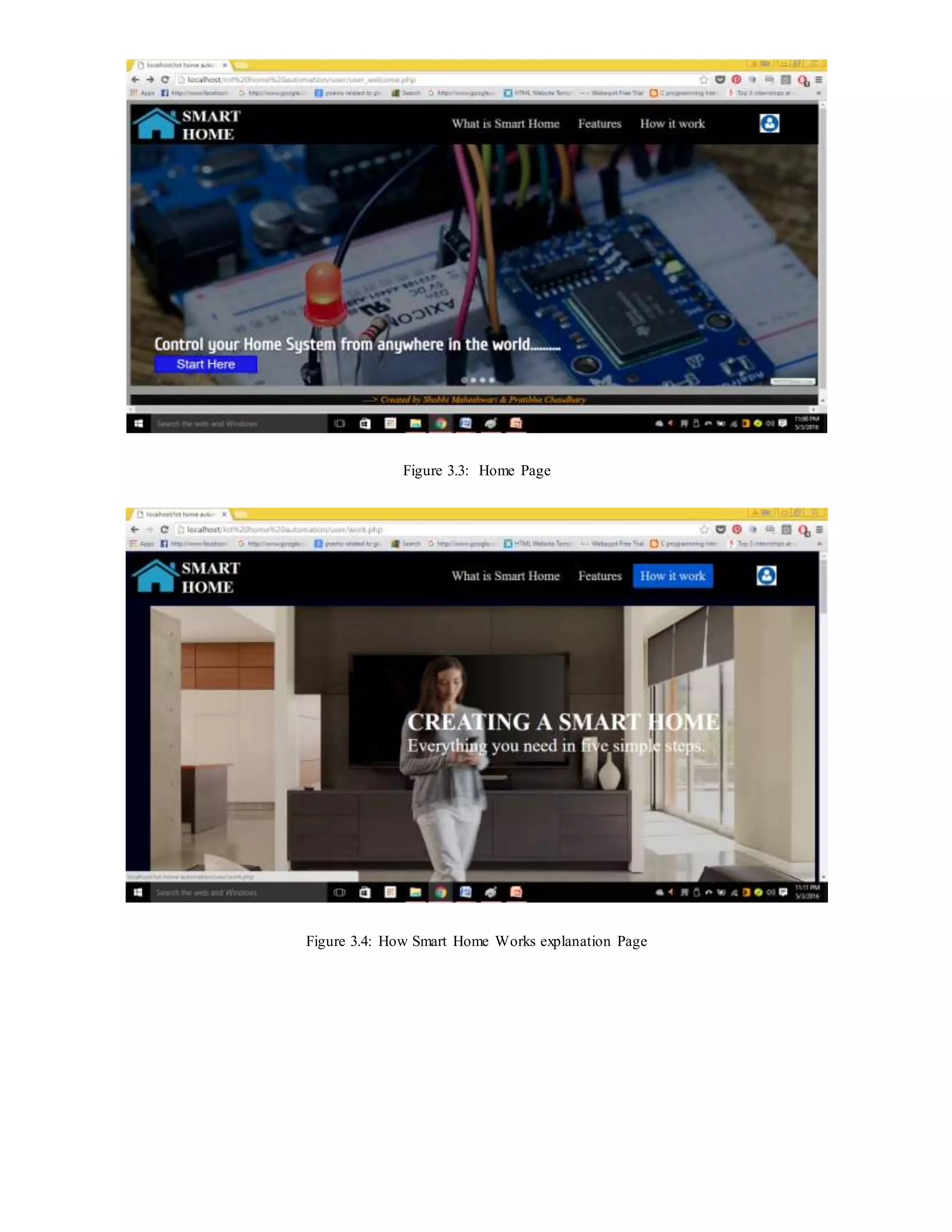
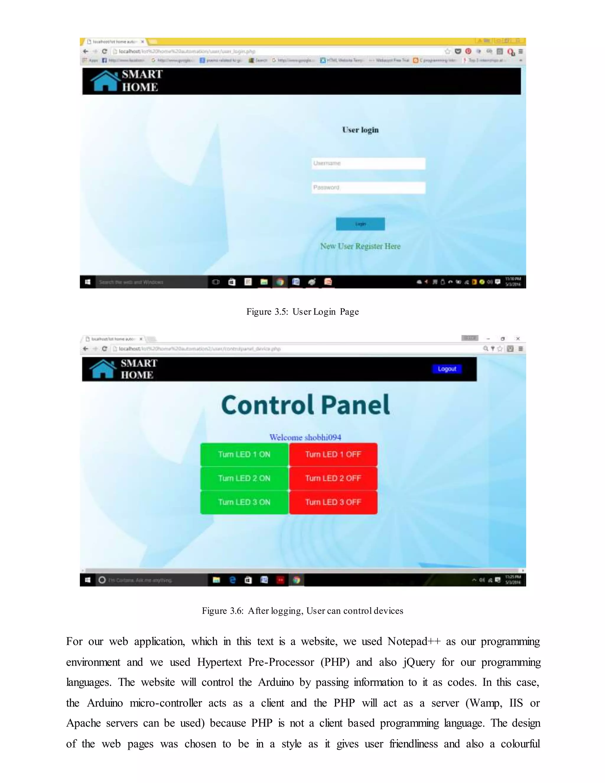
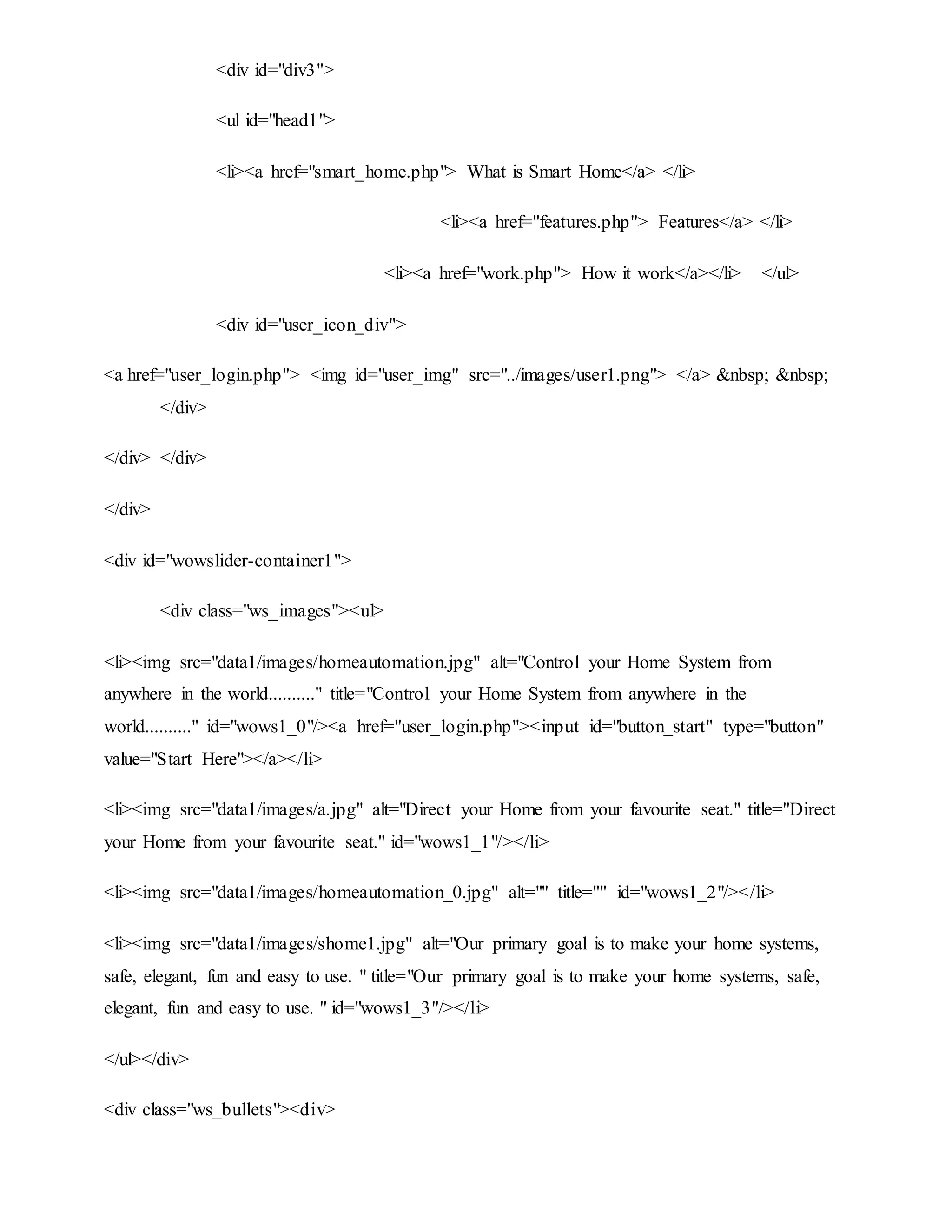
The project report on 'IoT Home Automation System' details the design and implementation of a system that enables users to control home devices remotely via a web application, utilizing Arduino, PHP, and MySQL. It emphasizes the importance of IoT in enhancing home automation, providing accessibility, and improving quality of life, especially for the elderly. The project aims to ensure secure access for authorized users while addressing various technical requirements and system features.