1. The document discusses shear force and bending moment diagrams (SFD & BMD) for beams under different loading conditions.
2. It provides an example of calculating the SFD and BMD for a simply supported beam with three point loads, finding the reactions, shear forces and bending moments at various sections.
3. A second example calculates the SFD and BMD for a double side overhanging beam with a udl and point loads, including locating points of contraflexure.
Introduction to the presentation on Shear Force and Bending Moment Diagrams (SFD & BMD) by Mr. A.M. Kamble.
Analysis of shear forces (5kN, 10kN, 8kN) at a beam section, resulting forces are RA = 8.2 kN and RB = 14.8 kN.
Definitions of shear force and bending moment, where shear force is the sum of vertical forces, and bending moment is the sum of moment effects.
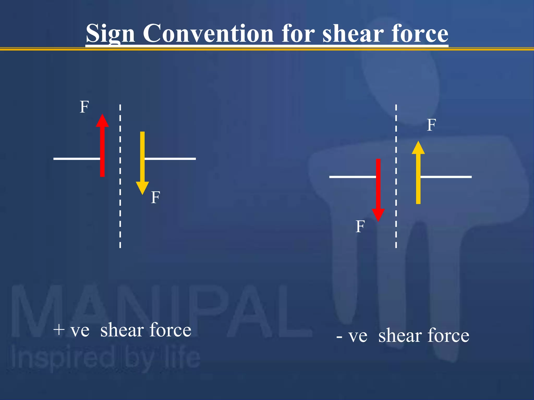
Sign conventions for shear forces and bending moments; positive and negative bending moments based on curvature types.
Explanation of Shear Force Diagrams (SFD) and Bending Moment Diagrams (BMD), showing variations along the beam length. Understanding the point of contra flexure and the relationship between load, shear force, and bending moment, detailing equilibrium conditions.
Variations of shear force and bending moment under different loading conditions illustrated in a table with type of loads.
Detailed example of shear force and bending moment calculation for a simply supported beam under point loads.
Calculation of reactions and shear forces for an overhanging beam subjected to various loads; positions of contra flexure identified.Additional calculations for a single side overhanging beam, determining maximum bending moments and locating points of contra flexure.
Performing analysis on a single side overhanging beam under various loads to determine reactions and bending moments.
Instructions and calculations for shear force and bending moment analysis of a cantilever beam with distributed and point loads.
Final review of exercise problems related to shear force and bending moment diagram drawing, further application of concepts learned.
Contact information for further queries related to the learning material presented.
Shear Force andBending Moment
Diagrams
[SFD & BMD]
Mr. A.M. Kamble
Visit for more Learning Resources
2.
Shear Force andBending Moments
Consider a section x-x at a distance 6m from left hand support A
5kN 10kN 8kN
4m 5m 5m 1m
A
C D
B
RA = 8.2 kN RB=14.8kN
E
x
x
6 m
Imagine the beam is cut into two pieces at section x-x and is separated, as
shown in figure
3.
To find theforces experienced by the section, consider any one portion of the
beam. Taking left hand portion
Transverse force experienced = 8.2 – 5 = 3.2 kN (upward)
Moment experienced = 8.2 × 6 – 5 × 2 = 39.2 kN-m (clockwise)
If we consider the right hand portion, we get
Transverse force experienced = 14.8 – 10 – 8 =-3.2 kN = 3.2 kN (downward)
Moment experienced = - 14.8 × 9 +8 × 8 + 10 × 3 = -39.2 kN-m = 39.2 kN-m
(anticlockwise)
5kN
A
8.2 kN
10kN 8kN B
14.8 kN
4 m
6 m
9 m
1 m
5 m
4.
5kN
A
8.2 kN
10kN 8kNB
14.8 kN
3.2 kN
3.2 kN
39.2 kN-m
39.2 kN-m
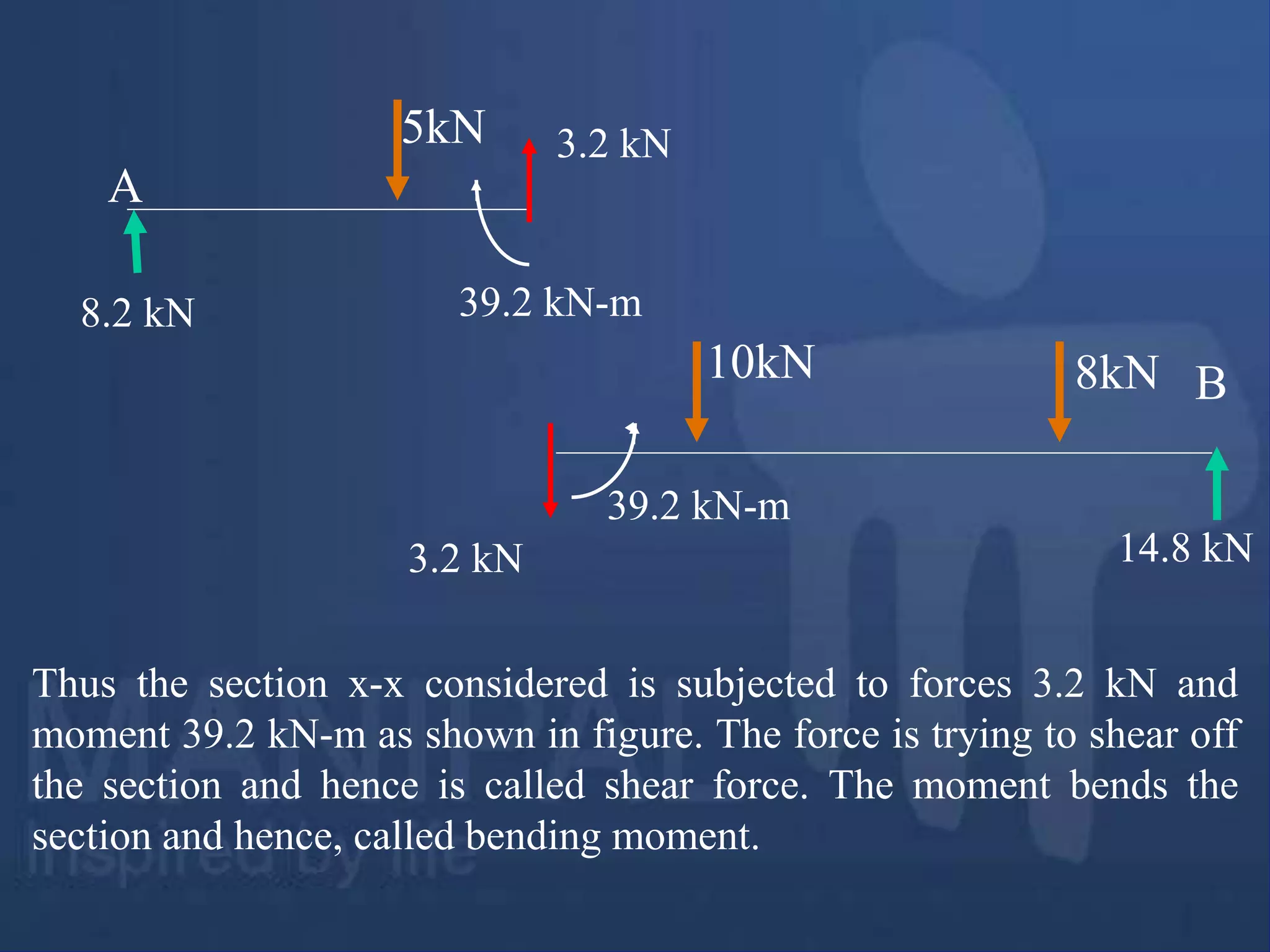
Thus the section x-x considered is subjected to forces 3.2 kN and
moment 39.2 kN-m as shown in figure. The force is trying to shear off
the section and hence is called shear force. The moment bends the
section and hence, called bending moment.
5.
Shear force ata section: The algebraic sum of the vertical forces
acting on the beam either to the left or right of the section is
known as the shear force at a section.
Bending moment (BM) at section: The algebraic sum of the moments
of all forces acting on the beam either to the left or right of the
section is known as the bending moment at a section
3.2 kN
3.2 kN
F
F
Shear force at x-x
M
Bending moment at x-x
39.2 kN
6.
Moment and Bendingmoment
Bending Moment (BM): The moment which causes the
bending effect on the beam is called Bending Moment. It is
generally denoted by ‘M’ or ‘BM’.
Moment: It is the product of force and perpendicular
distance between line of action of the force and the point
about which moment is required to be calculated.
Sign convention forbending moments:
The bending moment is considered as Sagging Bending
Moment if it tends to bend the beam to a curvature having
convexity at the bottom as shown in the Fig. given below.
Sagging Bending Moment is considered as positive bending
moment.
Fig. Sagging bending moment [Positive bending moment
]
Convexity
9.
Sign convention forbending moments:
Similarly the bending moment is considered as hogging
bending moment if it tends to bend the beam to a
curvature having convexity at the top as shown in the
Fig. given below. Hogging Bending Moment is
considered as Negative Bending Moment.
Fig. Hogging bending moment [Negative bending moment ]
Convexity
10.
Shear Force andBending Moment Diagrams
(SFD & BMD)
Shear Force Diagram (SFD):
The diagram which shows the variation of shear force
along the length of the beam is called Shear Force
Diagram (SFD).
Bending Moment Diagram (BMD):
The diagram which shows the variation of bending
moment along the length of the beam is called
Bending Moment Diagram (BMD).
11.
Point of Contraflexure [Inflection point]:
It is the point on the bending moment diagram where
bending moment changes the sign from positive to
negative or vice versa.
It is also called ‘Inflection point’. At the point of
inflection point or contra flexure the bending moment
is zero.
12.
Relationship between load,shear force and
bending moment
Fig. A simply supported beam subjected to general type loading
L
w kN/m
x
x
x1
x1
dx
The above Fig. shows a simply supported beam subjected to a general
type of loading. Consider a differential element of length ‘dx’ between
any two sections x-x and x1-x1 as shown.
13.
dx
v
V+dV
M M+dM
Fig. FBDof Differential element of the beam
x
x x1
x1
w kN/m
O
Taking moments about the point ‘O’ [Bottom-Right corner of the
differential element ]
- M + (M+dM) – V.dx – w.dx.dx/2 = 0
V.dx = dM
dx
dM
v
It is the relation between shear force and BM
Neglecting the small quantity of higher order
14.
dx
v
V+dV
M M+dM
Fig. FBDof Differential element of the beam
x
x x1
x1
w kN/m
O
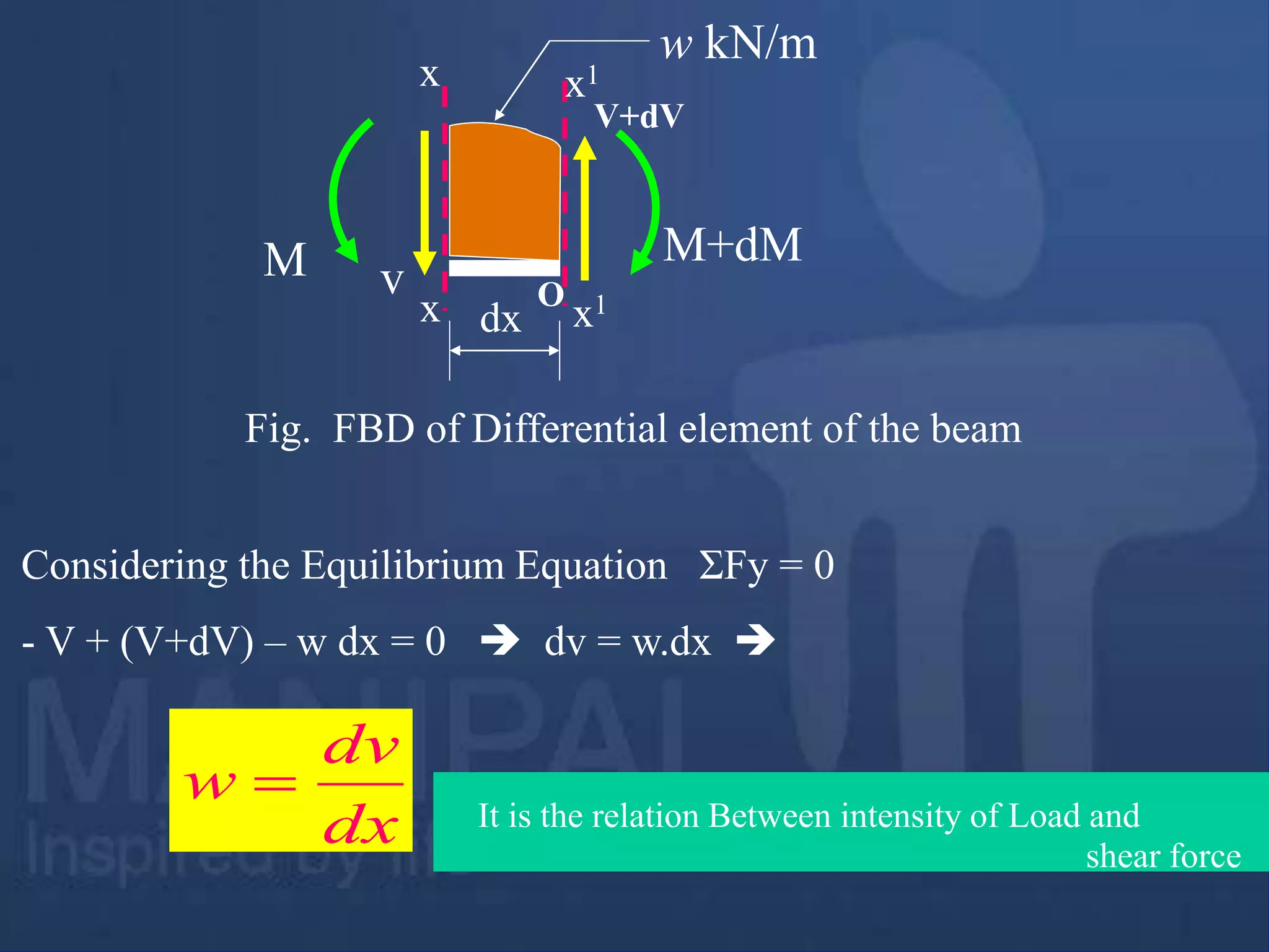
Considering the Equilibrium Equation ΣFy = 0
- V + (V+dV) – w dx = 0 dv = w.dx
dx
dv
w
It is the relation Between intensity of Load and
shear force
15.
Variation of Shearforce and bending moments
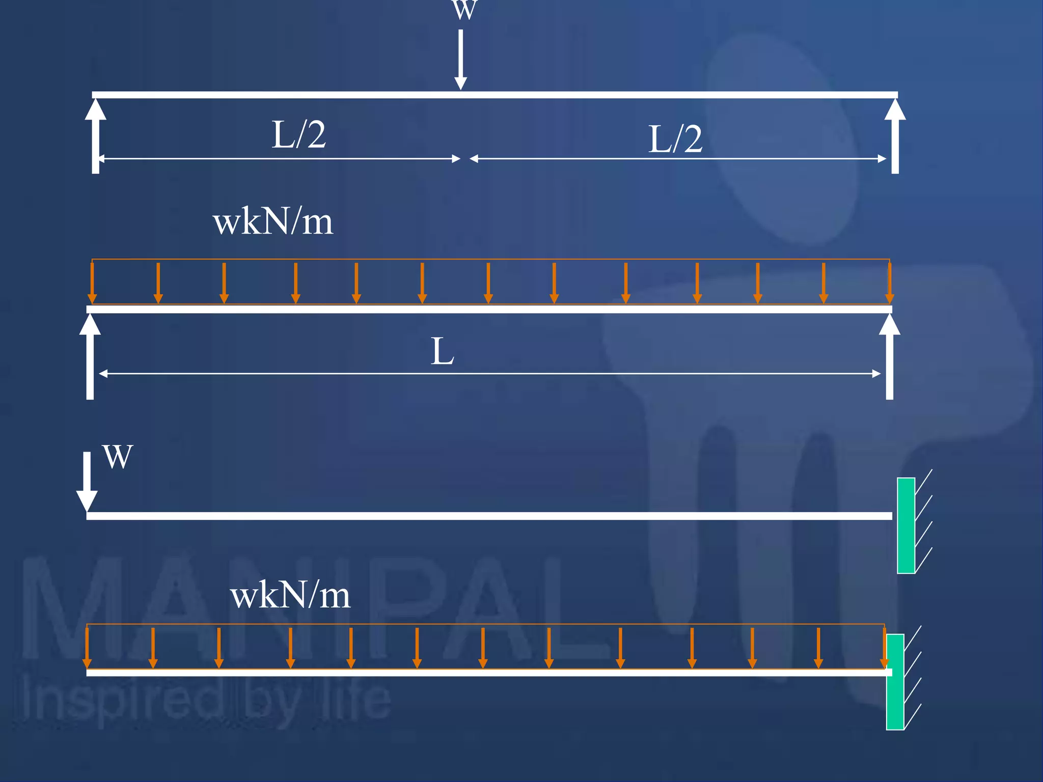
Variation of Shear force and bending moments for various standard
loads are as shown in the following Table
Type of load
SFD/BMD
Between point
loads OR for no
load region
Uniformly
distributed load
Uniformly
varying load
Shear Force
Diagram
Horizontal line Inclined line Two-degree curve
(Parabola)
Bending
Moment
Diagram
Inclined line Two-degree curve
(Parabola)
Three-degree
curve (Cubic-
parabola)
Table: Variation of Shear force and bending moments
16.
Sections for ShearForce and Bending Moment Calculations:
Shear force and bending moments are to be calculated at various
sections of the beam to draw shear force and bending moment diagrams.
These sections are generally considered on the beam where the
magnitude of shear force and bending moments are changing abruptly.
Therefore these sections for the calculation of shear forces include
sections on either side of point load, uniformly distributed load or
uniformly varying load where the magnitude of shear force changes
abruptly.
The sections for the calculation of bending moment include position
of point loads, either side of uniformly distributed load, uniformly
varying load and couple
Note: While calculating the shear force and bending moment, only the
portion of the udl which is on the left hand side of the section should
be converted into point load. But while calculating the reaction we
convert entire udl to point load
17.
Example Problem 1
E
5N10N 8N
2m 2m 3m 1m
A
C D
B
1. Draw shear force and bending moment diagrams [SFD
and BMD] for a simply supported beam subjected to
three point loads as shown in the Fig. given below.
18.
E
5N 10N 8N
2m2m 3m 1m
A
C D
B
Solution:
Using the condition: ΣMA = 0
- RB × 8 + 8 × 7 + 10 × 4 + 5 × 2 = 0 RB = 13.25 N
Using the condition: ΣFy = 0
RA + 13.25 = 5 + 10 + 8 RA = 9.75 N
RA RB
[Clockwise moment is Positive]
19.
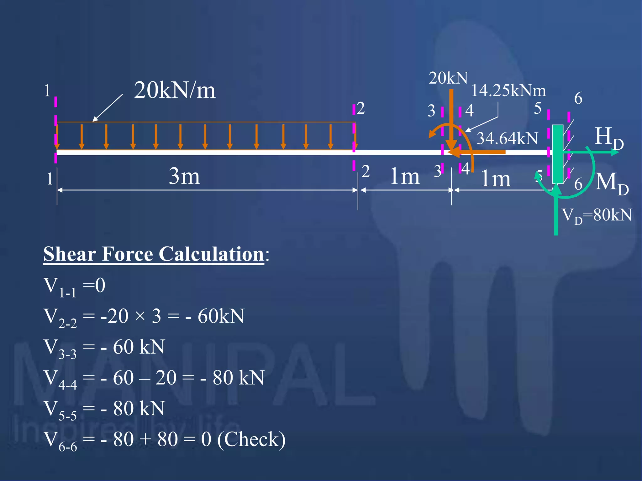
Shear Force atthe section 1-1 is denoted as V1-1
Shear Force at the section 2-2 is denoted as V2-2 and so on...
V0-0 = 0; V1-1 = + 9.75 N V6-6 = - 5.25 N
V2-2 = + 9.75 N V7-7 = 5.25 – 8 = -13.25 N
V3-3 = + 9.75 – 5 = 4.75 N V8-8 = -13.25
V4-4 = + 4.75 N V9-9 = -13.25 +13.25 = 0
V5-5 = +4.75 – 10 = - 5.25 N (Check)
5N 10N 8N
2m 2m 3m 1m
RA = 9.75 N RB=13.25N
1
1
1
2
2
3
3
4
4
5
5
6
6
7
7
8 9
8 9
0
0
Shear Force Calculation:
20.
5N 10N 8N
2m2m 3m 1m
A
C D E
B
9.75N 9.75N
4.75N 4.75N
5.25N 5.25N
13.25N 13.25N
SFD
21.
5N 10N 8N
2m2m 3m 1m
A
C D E
B
9.75N 9.75N
4.75N 4.75N
5.25N 5.25N
13.25N 13.25N
SFD
22.
Bending moment atA is denoted as MA
Bending moment at B is denoted as MB
and so on…
MA = 0 [ since it is simply supported]
MC = 9.75 × 2= 19.5 Nm
MD = 9.75 × 4 – 5 × 2 = 29 Nm
ME = 9.75 × 7 – 5 × 5 – 10 × 3 = 13.25 Nm
MB = 9.75 × 8 – 5 × 6 – 10 × 4 – 8 × 1 = 0
or MB = 0 [ since it is simply supported]
Bending Moment Calculation
23.
5N 10N 8N
2m2m 3m 1m
19.5Nm
29Nm
13.25Nm
BMD
A B
C D E
24.
E
5N 10N 8N
2m2m 3m 1m
A
C D
B
BMD
19.5Nm
29Nm
13.25Nm
9.75N 9.75N
4.75N 4.75N
5.25N 5.25N
13.25N 13.25N
SFD
Example Problem 1
VM-34
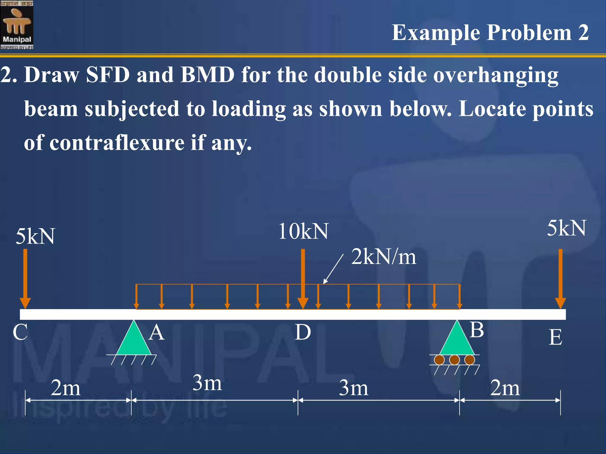
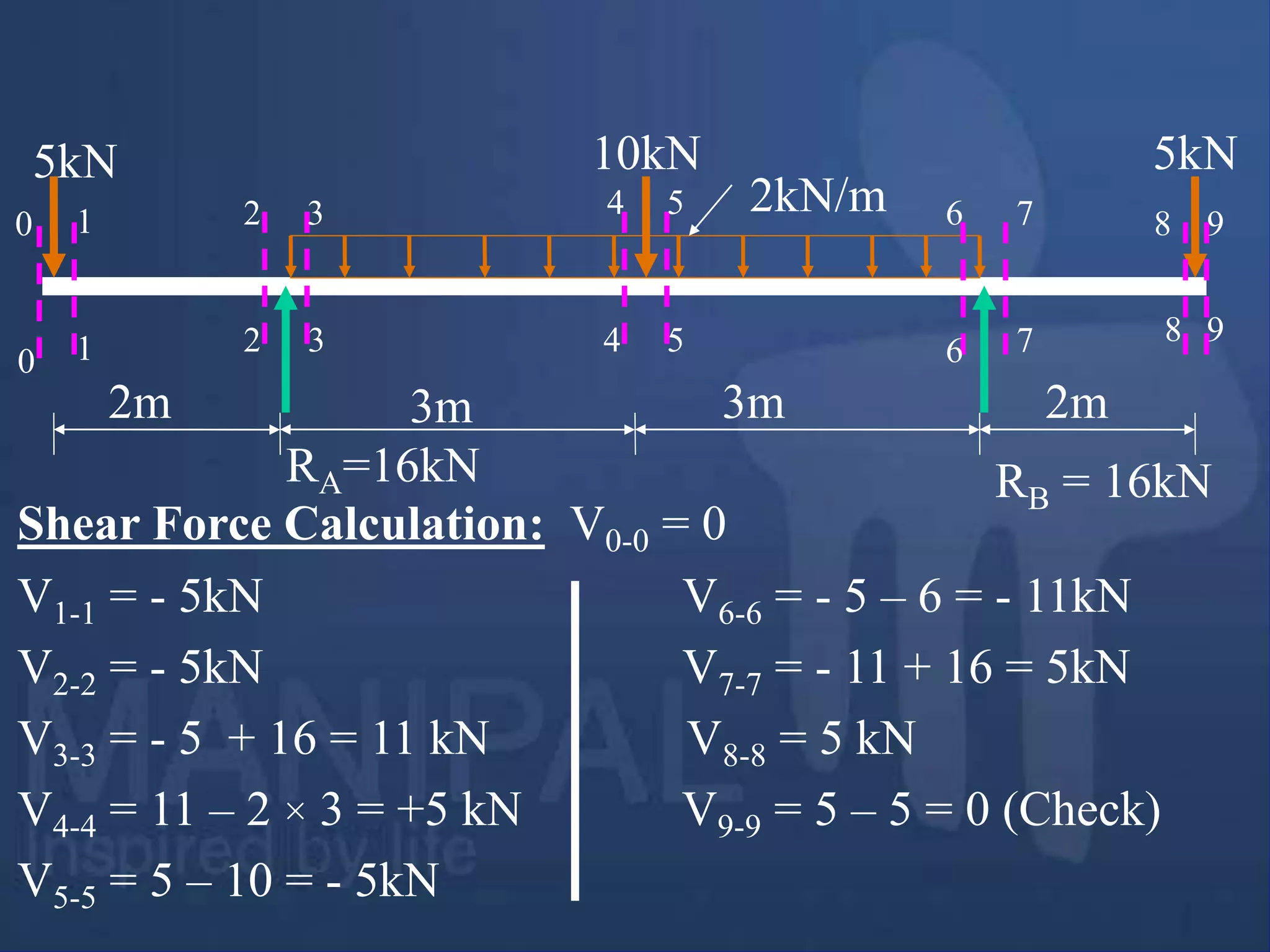
2. Draw SFDand BMD for the double side overhanging
beam subjected to loading as shown below. Locate points
of contraflexure if any.
5kN
2m 3m 3m 2m
5kN 10kN
2kN/m
A B
C D E
Example Problem 2
27.
2m 3m 3m2m
5kN 10kN 5kN
2kN/m
A B
C D E
Solution:
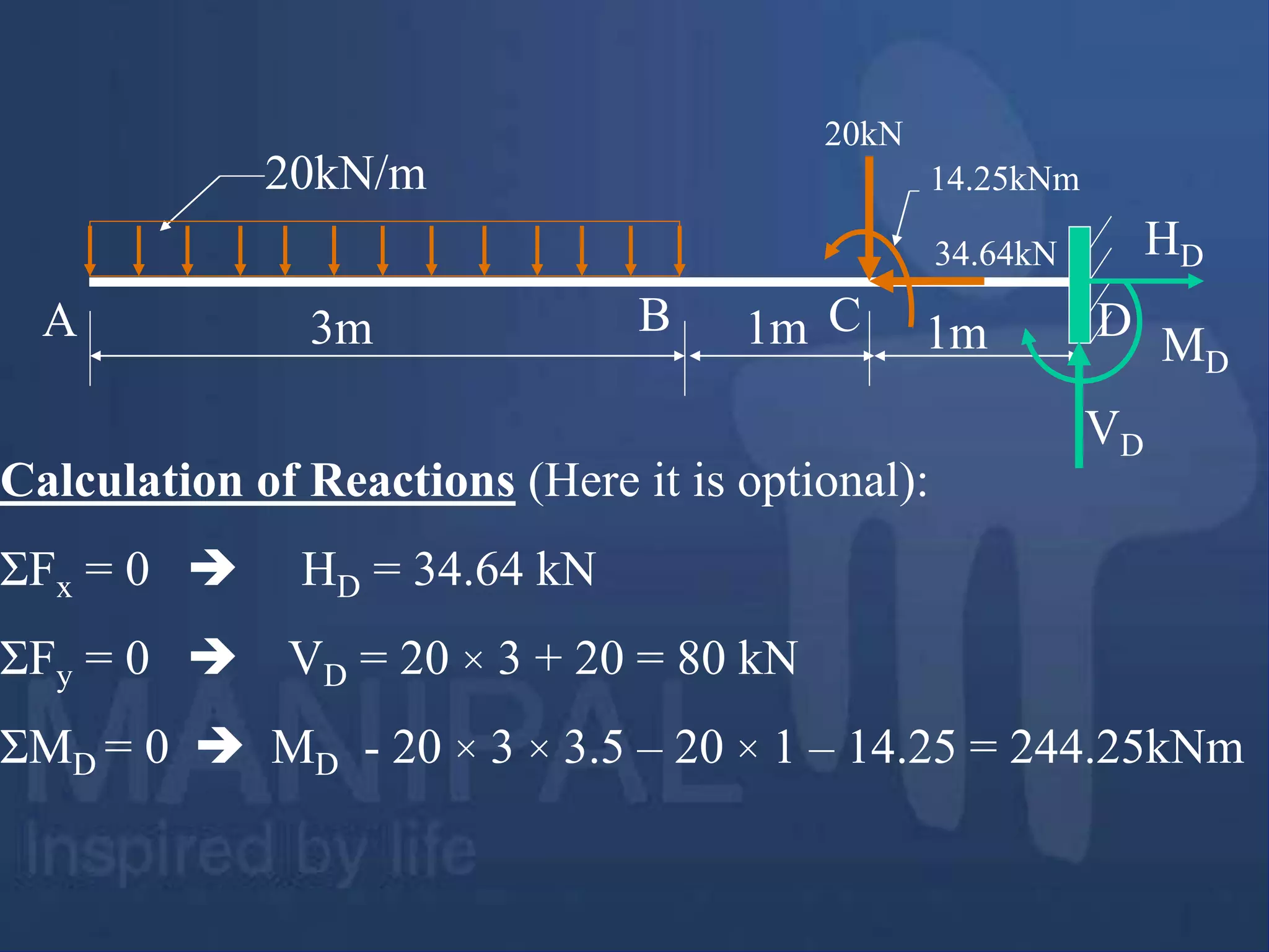
Calculation of Reactions:
Due to symmetry of the beam, loading and boundary
conditions, reactions at both supports are equal.
.`. RA = RB = ½(5+10+5+2 × 6) = 16 kN
RA RB
2m 3m 3m2m
5kN 10kN 5kN
2kN/m
A B
C D E
5kN
+
+
5kN 5kN
5kN 5kN 5kN
11kN
11kN
SFD
30.
2m 3m 3m2m
5kN 10kN 5kN
2kN/m
A B
C D E
Bending Moment Calculation:
MC = ME = 0 [Because Bending moment at free end is zero]
MA = MB = - 5 × 2 = - 10 kNm
MD = - 5 × 5 + 16 × 3 – 2 × 3 × 1.5 = +14 kNm
RA=16kN RB = 16kN
31.
2m 3m 3m2m
5kN 10kN 5kN
2kN/m
A B
C D E
10kNm
10kNm
14kNm
BMD
32.
2m 3m 3m2m
5kN 10kN 5kN
2kN/m
A B
C D E
10kNm 10kNm
14kNm
BMD
+
+
5kN 5kN
5kN 5kN 5kN
11kN
11kN
SFD
33.
10kNm 10kNm
Let xbe the distance of point of contra flexure from support A
Taking moments at the section x-x (Considering left portion)
0
2
2
16
)
2
(
5
2
x
x
x
M x
x
x = 1 or 10
.`. x = 1 m
x
x
x
x
Points of contra flexure
2m 3m 3m 2m
5kN 10kN 5kN
2kN/m
A B
C D E
34.
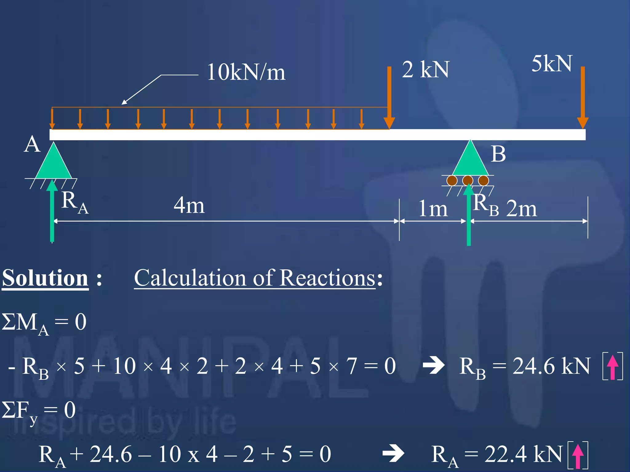
3. Draw SFDand BMD for the single side overhanging beam
subjected to loading as shown below. Determine the
absolute maximum bending moment and shear forces and
mark them on SFD and BMD. Also locate points of contra
flexure if any.
4m 1m 2m
2 kN 5kN
10kN/m
A
B
C D
Example Problem
Example Problem 3
35.
4m 1m 2m
2kN 5kN
10kN/m
A B
RA RB
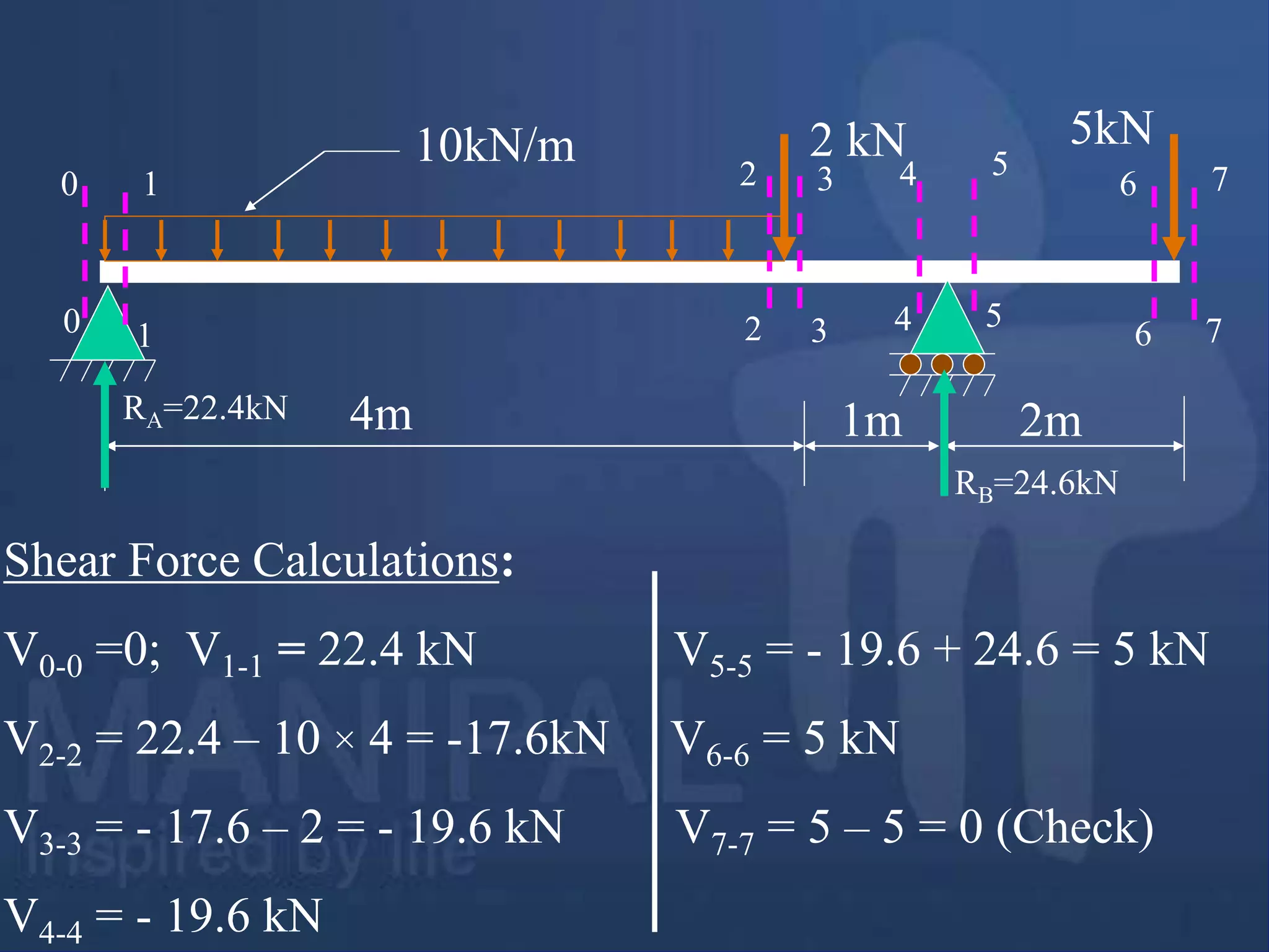
Solution : Calculation of Reactions:
ΣMA = 0
- RB × 5 + 10 × 4 × 2 + 2 × 4 + 5 × 7 = 0 RB = 24.6 kN
ΣFy = 0
RA + 24.6 – 10 x 4 – 2 + 5 = 0 RA = 22.4 kN
4m 1m 2m
2kN 5kN
10kN/m
RA=22.4kN
RB=24.6kN
22.4kN
19.6kN 19.6kN
17.6kN
5 kN 5 kN
SFD
x = 2.24m
A
C B D
38.
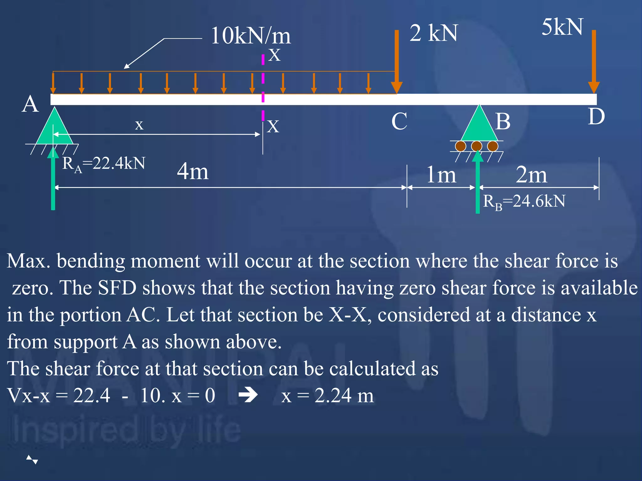
Max. bending momentwill occur at the section where the shear force is
zero. The SFD shows that the section having zero shear force is available
in the portion AC. Let that section be X-X, considered at a distance x
from support A as shown above.
The shear force at that section can be calculated as
Vx-x = 22.4 - 10. x = 0 x = 2.24 m
4m 1m 2m
2 kN 5kN
10kN/m
A
B
C D
RA=22.4kN
RB=24.6kN
X
X
x
39.
Calculations of BendingMoments:
MA = MD = 0
MC = 22.4 × 4 – 10 × 4 × 2 = 9.6 kNm
MB = 22.4 × 5 – 10 × 4 × 3 – 2 × 1 = - 10kNm (Considering Left portion
of the section)
Alternatively
MB = -5 × 2 = -10 kNm (Considering Right portion of the section)
Absolute Maximum Bending Moment is at X- X ,
Mmax = 22.4 × 2.24 – 10 × (2.24)2 / 2 = 25.1 kNm
4m 1m 2m
2 kN 5kN
10kN/m
A
B
C D
RA=22.4kN
RB=24.6kN
40.
4m 1m 2m
2kN 5kN
10kN/m
A
B
C D
RA=22.4kN
RB=24.6kN
X
X
x = 2.24m
9.6kNm
10kNm
BMD
Point of
contra flexure
Mmax = 25.1 kNm
Calculations of AbsoluteMaximum Bending Moment:
Max. bending moment will occur at the section where the shear force is
zero. The SFD shows that the section having zero shear force is available
in the portion AC. Let that section be X-X, considered at a distance x
from support A as shown above.
The shear force at that section can be calculated as
Vx-x = 22.4 - 10. x = 0 x = 2.24 m
Max. BM at X- X ,
Mmax = 22.4 × 2.24 – 10 × (2.24)2 / 2 = 25.1 kNm
4m 1m 2m
2 kN 5kN
10kN/m
A
B
C D
RA=22.4kN
RB=24.6kN
X
X
x
43.
4m 1m 2m
2kN 5kN
10kN/m
A
B
C D
RA=22.4kN
RB=24.6kN
X
X
x = 2.24m
Mmax = 25.1 kNm
9.6kNm
10kNm
BMD
Point of
contra flexure
44.
Mmax = 25.1kNm
9.6kNm
10kNm
BMD
Point of
contra flexure
a
Let a be the distance of point of contra flexure from support B
Taking moments at the section A-A (Considering left portion)
A
A
0
6
.
24
)
2
(
5
a
a
M A
A
a = 0.51 m
45.
4. Draw SFDand BMD for the single side overhanging beam
subjected to loading as shown below. Mark salient points on
SFD and BMD.
60kN/m
20kN/m
20kN
3m 2m 2m
A
B
Example Problem 4
C D
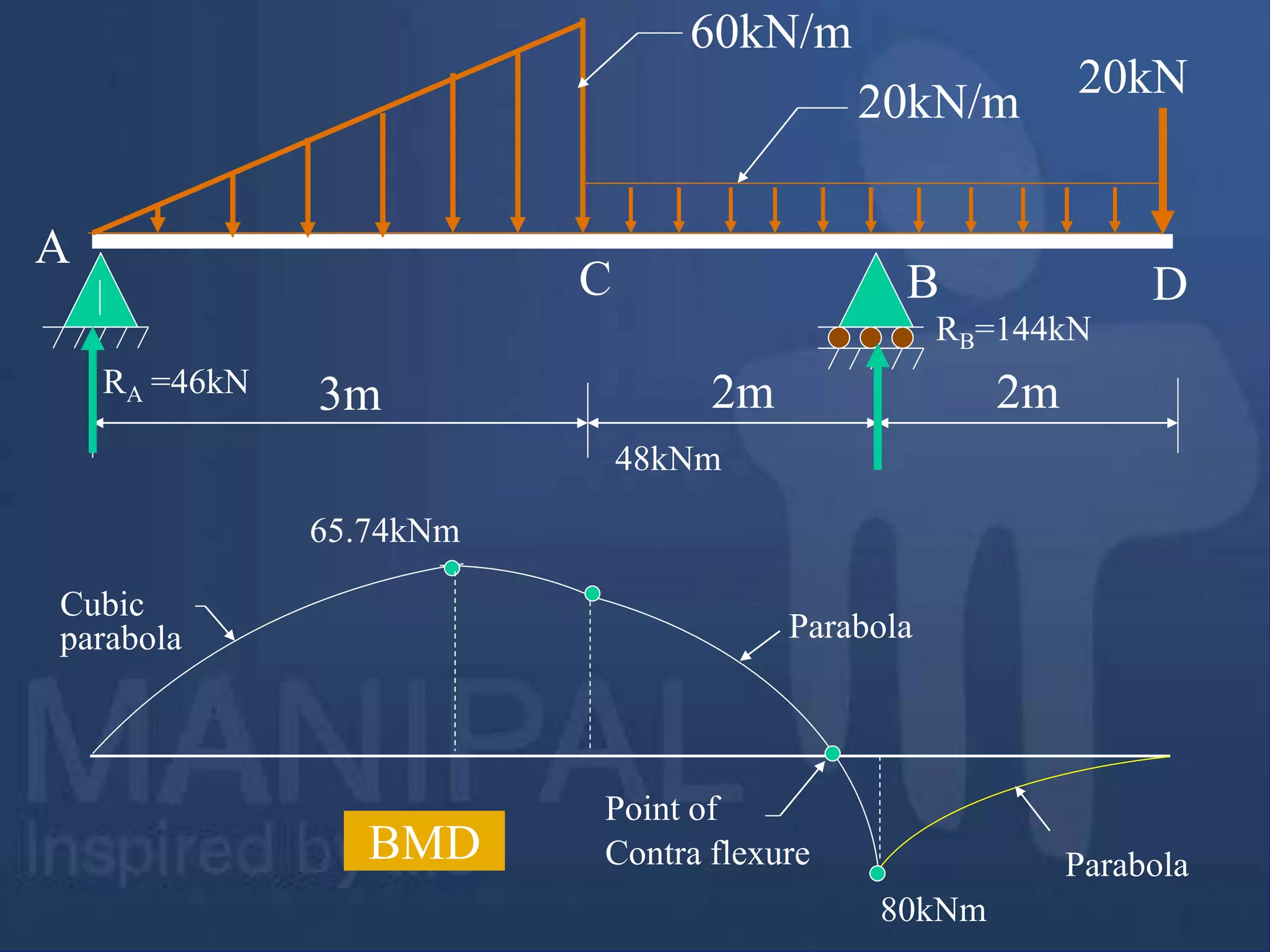
46.
60kN/m
3m
Solution: Calculation ofreactions:
ΣMA = 0
-RB × 5 + ½ × 3 × 60 × (2/3) × 3 +20 × 4 × 5 + 20 × 7 = 0 RB =144kN
ΣFy = 0
RA + 144 – ½ × 3 × 60 – 20 × 4 -20 = 0 RA = 46kN
20kN/m
20kN
2m 2m
A
B
RA RB
C D
60kN/m
20kN/m
20kN
3m 2m 2m
1
23
2 3 4
5 6
4
5 6
RA = 46kN
RB = 144kN
RA
RA
46kN
44kN
84kN
60kN
20kN
SFD
Parabola
1
Example Problem 4
49.
Max. bending momentwill occur at the section where the shear force is
zero. The SFD shows that the section having zero shear force is available
in the portion AC. Let that section be X-X, considered at a distance ‘x’
from support A as shown above. The shear force expression at that section
should be equated to zero. i.e.,
Vx-x = 46 – ½ .x. (60/3)x = 0 x = 2.145 m
60kN/m
3m
20kN/m
20kN
2m 2m
A
B
RA =46kN
C D
RB=144kN
X
X
x
50.
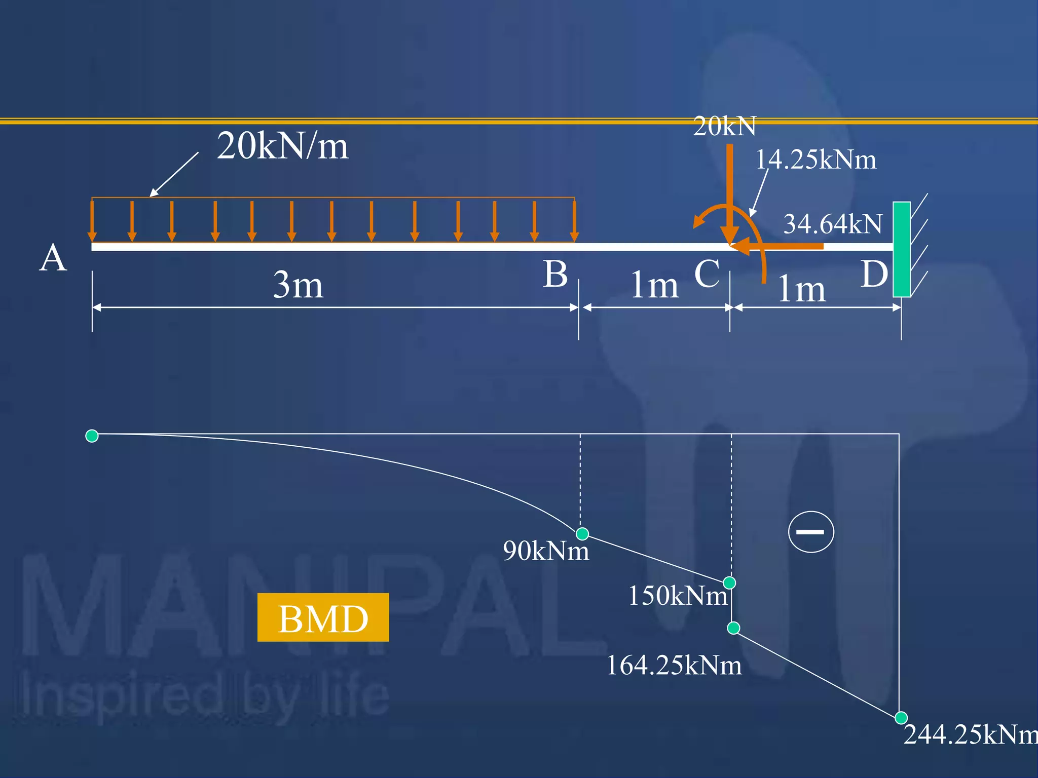
Calculation of bendingmoments:
MA = MD = 0
MC = 46 × 3 – ½ × 3 × 60 × (1/3 × 3) = 48 kNm[Considering LHS of
section]
MB = -20 × 2 – 20 × 2 × 1 = - 80 kNm [Considering RHS of section]
Absolute Maximum Bending Moment, Mmax = 46 × 2.145 – ½ × 2.145
×(2.145 × 60/3) × (1/3 × 2.145) = 65.74 kNm
60kN/m
3m
20kN/m
20kN
2m 2m
A
B
RA =46kN
C D
RB=144kN
Calculations of AbsoluteMaximum Bending Moment:
Max. bending moment will occur at the section where the shear force is
zero. The SFD shows that the section having zero shear force is available
in the portion AC. Let that section be X-X, considered at a distance ‘x’
from support A as shown above. The shear force expression at that section
should be equated to zero. i.e.,
Vx-x = 46 – ½ .x. (60/3)x = 0 x = 2.145 m
BM at X- X , Mmax = 46 × 2.145 – ½ × 2.145 ×(2.145 × 60/3) × (1/3 × 2.145)=65.74
kNm
60kN/m
3m
20kN/m
20kN
2m 2m
A
B
RA =46kN
C D
RB=144kN
X
X
x=2.145m
Point of contraflexure:
BMD shows that point of contra flexure is existing in the
portion CB. Let ‘a’ be the distance in the portion CB from the
support B at which the bending moment is zero. And that ‘a’
can be calculated as given below.
ΣMx-x = 0
0
2
)
2
(
20
)
2
(
20
144
2
a
a
a
a = 1.095 m
56.
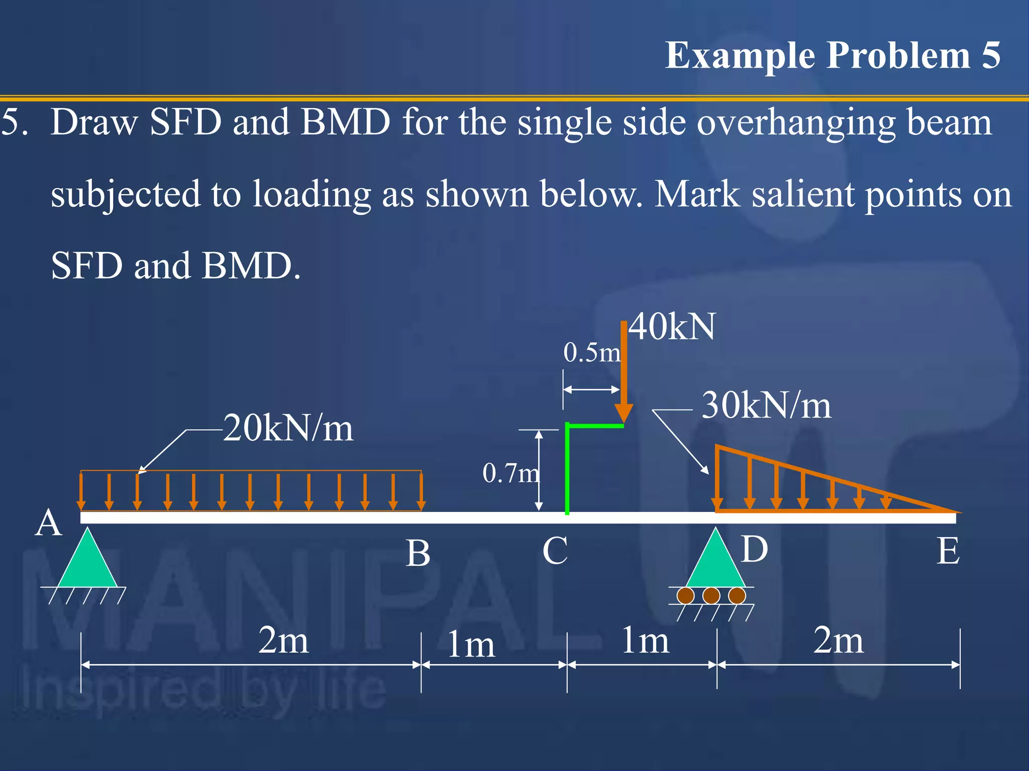
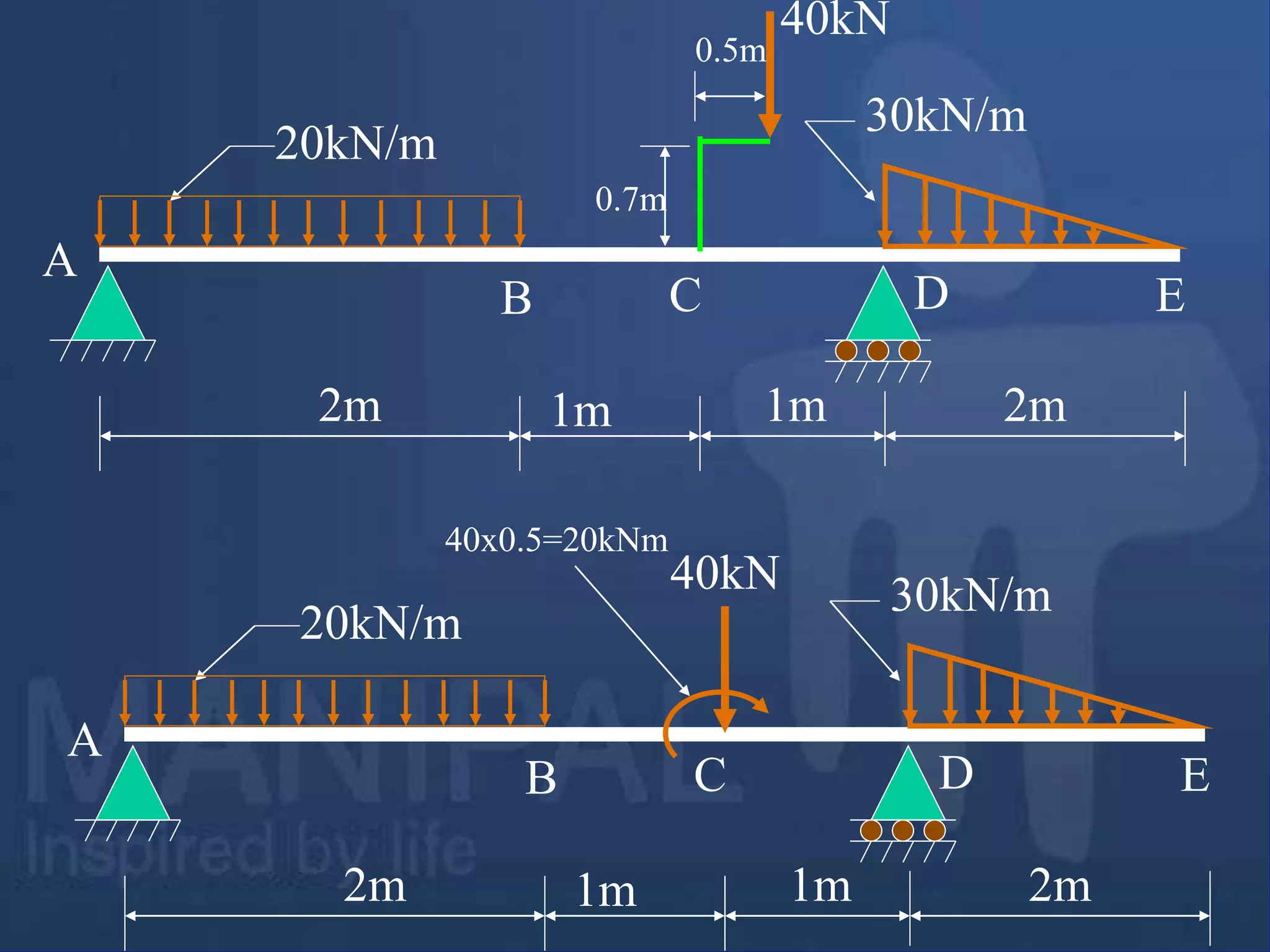
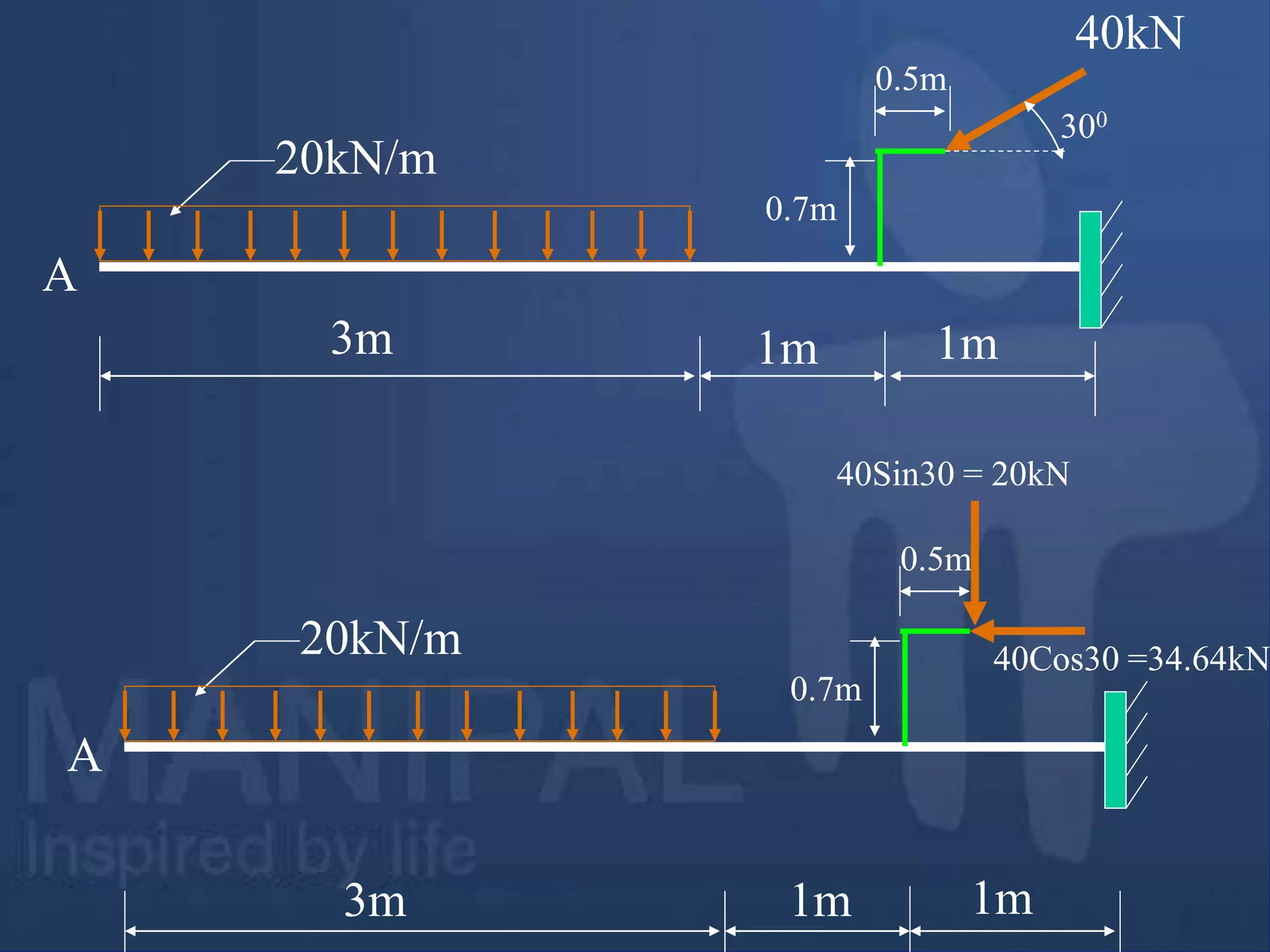
5. Draw SFDand BMD for the single side overhanging beam
subjected to loading as shown below. Mark salient points on
SFD and BMD.
20kN/m
30kN/m
40kN
2m 2m
A
D
1m 1m
0.7m
0.5m
B C E
Example Problem 5
Exercise Problems
1. DrawSFD and BMD for a single side overhanging beam
subjected to loading as shown below. Mark absolute
maximum bending moment on bending moment diagram and
locate point of contra flexure.
20kN/m
5kNm
15kN/m
10kN
3m 1m 1m 2m
1m 1m
[Ans: Absolute maximum BM = 60.625 kNm ]
VM-73
74.
10kN 16kN
1m
A B
2.Draw shear force and bending moment diagrams [SFD
and BMD] for a simply supported beam subjected to
loading as shown in the Fig. given below. Also locate
and determine absolute maximum bending moment.
4kN/m
1m 1m 1m
2m
600
[Ans: Absolute maximum bending moment = 22.034kNm
Its position is 3.15m from Left hand support ]
Exercise Problems VM-74
75.
50kN
A
3. Draw shearforce and bending moment diagrams [SFD
and BMD] for a single side overhanging beam subjected
to loading as shown in the Fig. given below. Locate
points of contra flexure if any.
10kN/m
1m 1m 3m
[Ans : Position of point of contra flexure from RHS = 0.375m]
Exercise Problems
25kN/m
10kNm
B
2m
VM-75
76.
8kN
4. Draw SFDand BMD for a double side overhanging beam
subjected to loading as shown in the Fig. given below.
Locate the point in the AB portion where the bending
moment is zero.
4kN/m
[Ans : Bending moment is zero at mid span]
Exercise Problems
B
2m
8kN
16kN
2m 2m 2m
A
VM-76
77.
5. A singleside overhanging beam is subjected to uniformly distributed
load of 4 kN/m over AB portion of the beam in addition to its self
weight 2 kN/m acting as shown in the Fig. given below. Draw SFD
and BMD for the beam. Locate the inflection points if any. Also locate
and determine maximum negative and positive bending moments.
4kN/m
[Ans :Max. positive bending moment is located at 2.89 m from LHS.
and whose value is 37.57 kNm ]
Exercise Problems
B
2m
6m
A
2kN/m
VM-77
78.
5kN
6. Three pointloads and one uniformly distributed load are
acting on a cantilever beam as shown in the Fig. given
below. Draw SFD and BMD for the beam. Locate and
determine maximum shear force and bending moments.
2kN/m
[Ans : Both Shear force and Bending moments are maximum
at supports.]
Exercise Problems
B
20kN
10kN
A
1m 1m 1m
VM-78
79.
200N 100N
A B
7.One side overhanging beam is subjected loading as
shown below. Draw shear force and bending moment
diagrams [SFD and BMD] for beam. Also determine
maximum hogging bending moment.
30N/m
4m
[Ans: Max. Hogging bending moment = 735 kNm]
Exercise Problems
4m
3m
VM-79
80.
5kN
8. A cantileverbeam of span 6m is subjected to three point
loads at 1/3rd points as shown in the Fig. given below.
Draw SFD and BMD for the beam. Locate and determine
maximum shear force and hogging bending moment.
[Ans : Max. Shear force = 20.5kN, Max BM= 71kNm
Both max. shear force and bending moments will occur
at supports.]
Exercise Problems
B
10kN
A 2m 2m 2m
300
0.5m 8kN 5kN
VM-80
81.
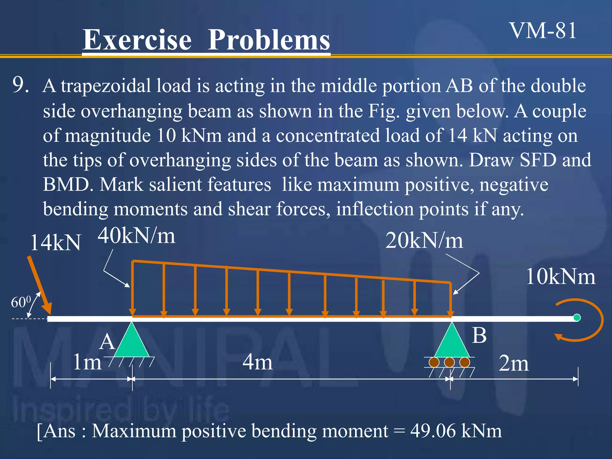
9. A trapezoidalload is acting in the middle portion AB of the double
side overhanging beam as shown in the Fig. given below. A couple
of magnitude 10 kNm and a concentrated load of 14 kN acting on
the tips of overhanging sides of the beam as shown. Draw SFD and
BMD. Mark salient features like maximum positive, negative
bending moments and shear forces, inflection points if any.
[Ans : Maximum positive bending moment = 49.06 kNm
Exercise Problems
14kN 40kN/m
B
2m
10kNm
1m
A
4m
20kN/m
600
VM-81
82.
10. Draw SFDand BMD for the single side overhanging beam
subjected loading as shown below.. Mark salient features like
maximum positive, negative bending moments and shear forces,
inflection points if any.
Exercise Problems
24kN
6kN/m
4kN/m
0.5m
1m 1m 3m 2m 3m
Ans: Maximum positive bending moment = 41.0 kNm
VM-82
![Shear Force and Bending Moment
Diagrams
[SFD & BMD]
Mr. A.M. Kamble
Visit for more Learning Resources](https://image.slidesharecdn.com/sfdbmd-230410145649-b841dd28/75/SFD-BMD-ppt-1-2048.jpg)


![Sign convention for bending moments:
The bending moment is considered as Sagging Bending
Moment if it tends to bend the beam to a curvature having
convexity at the bottom as shown in the Fig. given below.
Sagging Bending Moment is considered as positive bending
moment.
Fig. Sagging bending moment [Positive bending moment
]
Convexity](https://image.slidesharecdn.com/sfdbmd-230410145649-b841dd28/75/SFD-BMD-ppt-8-2048.jpg)
![Sign convention for bending moments:
Similarly the bending moment is considered as hogging
bending moment if it tends to bend the beam to a
curvature having convexity at the top as shown in the
Fig. given below. Hogging Bending Moment is
considered as Negative Bending Moment.
Fig. Hogging bending moment [Negative bending moment ]
Convexity](https://image.slidesharecdn.com/sfdbmd-230410145649-b841dd28/75/SFD-BMD-ppt-9-2048.jpg)

![Point of Contra flexure [Inflection point]:
It is the point on the bending moment diagram where
bending moment changes the sign from positive to
negative or vice versa.
It is also called ‘Inflection point’. At the point of
inflection point or contra flexure the bending moment
is zero.](https://image.slidesharecdn.com/sfdbmd-230410145649-b841dd28/75/SFD-BMD-ppt-11-2048.jpg)

![dx
v
V+dV
M M+dM
Fig. FBD of Differential element of the beam
x
x x1
x1
w kN/m
O
Taking moments about the point ‘O’ [Bottom-Right corner of the
differential element ]
- M + (M+dM) – V.dx – w.dx.dx/2 = 0
V.dx = dM
dx
dM
v
It is the relation between shear force and BM
Neglecting the small quantity of higher order](https://image.slidesharecdn.com/sfdbmd-230410145649-b841dd28/75/SFD-BMD-ppt-13-2048.jpg)


![Example Problem 1
E
5N 10N 8N
2m 2m 3m 1m
A
C D
B
1. Draw shear force and bending moment diagrams [SFD
and BMD] for a simply supported beam subjected to
three point loads as shown in the Fig. given below.](https://image.slidesharecdn.com/sfdbmd-230410145649-b841dd28/75/SFD-BMD-ppt-17-2048.jpg)
![E
5N 10N 8N
2m 2m 3m 1m
A
C D
B
Solution:
Using the condition: ΣMA = 0
- RB × 8 + 8 × 7 + 10 × 4 + 5 × 2 = 0 RB = 13.25 N
Using the condition: ΣFy = 0
RA + 13.25 = 5 + 10 + 8 RA = 9.75 N
RA RB
[Clockwise moment is Positive]](https://image.slidesharecdn.com/sfdbmd-230410145649-b841dd28/75/SFD-BMD-ppt-18-2048.jpg)


![Bending moment at A is denoted as MA
Bending moment at B is denoted as MB
and so on…
MA = 0 [ since it is simply supported]
MC = 9.75 × 2= 19.5 Nm
MD = 9.75 × 4 – 5 × 2 = 29 Nm
ME = 9.75 × 7 – 5 × 5 – 10 × 3 = 13.25 Nm
MB = 9.75 × 8 – 5 × 6 – 10 × 4 – 8 × 1 = 0
or MB = 0 [ since it is simply supported]
Bending Moment Calculation](https://image.slidesharecdn.com/sfdbmd-230410145649-b841dd28/75/SFD-BMD-ppt-22-2048.jpg)


![2m 3m 3m 2m
5kN 10kN 5kN
2kN/m
A B
C D E
Bending Moment Calculation:
MC = ME = 0 [Because Bending moment at free end is zero]
MA = MB = - 5 × 2 = - 10 kNm
MD = - 5 × 5 + 16 × 3 – 2 × 3 × 1.5 = +14 kNm
RA=16kN RB = 16kN](https://image.slidesharecdn.com/sfdbmd-230410145649-b841dd28/75/SFD-BMD-ppt-30-2048.jpg)


![Calculation of bending moments:
MA = MD = 0
MC = 46 × 3 – ½ × 3 × 60 × (1/3 × 3) = 48 kNm[Considering LHS of
section]
MB = -20 × 2 – 20 × 2 × 1 = - 80 kNm [Considering RHS of section]
Absolute Maximum Bending Moment, Mmax = 46 × 2.145 – ½ × 2.145
×(2.145 × 60/3) × (1/3 × 2.145) = 65.74 kNm
60kN/m
3m
20kN/m
20kN
2m 2m
A
B
RA =46kN
C D
RB=144kN](https://image.slidesharecdn.com/sfdbmd-230410145649-b841dd28/75/SFD-BMD-ppt-50-2048.jpg)


![Exercise Problems
1. Draw SFD and BMD for a single side overhanging beam
subjected to loading as shown below. Mark absolute
maximum bending moment on bending moment diagram and
locate point of contra flexure.
20kN/m
5kNm
15kN/m
10kN
3m 1m 1m 2m
1m 1m
[Ans: Absolute maximum BM = 60.625 kNm ]
VM-73](https://image.slidesharecdn.com/sfdbmd-230410145649-b841dd28/75/SFD-BMD-ppt-73-2048.jpg)
![10kN 16kN
1m
A B
2. Draw shear force and bending moment diagrams [SFD
and BMD] for a simply supported beam subjected to
loading as shown in the Fig. given below. Also locate
and determine absolute maximum bending moment.
4kN/m
1m 1m 1m
2m
600
[Ans: Absolute maximum bending moment = 22.034kNm
Its position is 3.15m from Left hand support ]
Exercise Problems VM-74](https://image.slidesharecdn.com/sfdbmd-230410145649-b841dd28/75/SFD-BMD-ppt-74-2048.jpg)
![50kN
A
3. Draw shear force and bending moment diagrams [SFD
and BMD] for a single side overhanging beam subjected
to loading as shown in the Fig. given below. Locate
points of contra flexure if any.
10kN/m
1m 1m 3m
[Ans : Position of point of contra flexure from RHS = 0.375m]
Exercise Problems
25kN/m
10kNm
B
2m
VM-75](https://image.slidesharecdn.com/sfdbmd-230410145649-b841dd28/75/SFD-BMD-ppt-75-2048.jpg)
![8kN
4. Draw SFD and BMD for a double side overhanging beam
subjected to loading as shown in the Fig. given below.
Locate the point in the AB portion where the bending
moment is zero.
4kN/m
[Ans : Bending moment is zero at mid span]
Exercise Problems
B
2m
8kN
16kN
2m 2m 2m
A
VM-76](https://image.slidesharecdn.com/sfdbmd-230410145649-b841dd28/75/SFD-BMD-ppt-76-2048.jpg)
![5. A single side overhanging beam is subjected to uniformly distributed
load of 4 kN/m over AB portion of the beam in addition to its self
weight 2 kN/m acting as shown in the Fig. given below. Draw SFD
and BMD for the beam. Locate the inflection points if any. Also locate
and determine maximum negative and positive bending moments.
4kN/m
[Ans :Max. positive bending moment is located at 2.89 m from LHS.
and whose value is 37.57 kNm ]
Exercise Problems
B
2m
6m
A
2kN/m
VM-77](https://image.slidesharecdn.com/sfdbmd-230410145649-b841dd28/75/SFD-BMD-ppt-77-2048.jpg)
![5kN
6. Three point loads and one uniformly distributed load are
acting on a cantilever beam as shown in the Fig. given
below. Draw SFD and BMD for the beam. Locate and
determine maximum shear force and bending moments.
2kN/m
[Ans : Both Shear force and Bending moments are maximum
at supports.]
Exercise Problems
B
20kN
10kN
A
1m 1m 1m
VM-78](https://image.slidesharecdn.com/sfdbmd-230410145649-b841dd28/75/SFD-BMD-ppt-78-2048.jpg)
![200N 100N
A B
7. One side overhanging beam is subjected loading as
shown below. Draw shear force and bending moment
diagrams [SFD and BMD] for beam. Also determine
maximum hogging bending moment.
30N/m
4m
[Ans: Max. Hogging bending moment = 735 kNm]
Exercise Problems
4m
3m
VM-79](https://image.slidesharecdn.com/sfdbmd-230410145649-b841dd28/75/SFD-BMD-ppt-79-2048.jpg)
![5kN
8. A cantilever beam of span 6m is subjected to three point
loads at 1/3rd points as shown in the Fig. given below.
Draw SFD and BMD for the beam. Locate and determine
maximum shear force and hogging bending moment.
[Ans : Max. Shear force = 20.5kN, Max BM= 71kNm
Both max. shear force and bending moments will occur
at supports.]
Exercise Problems
B
10kN
A 2m 2m 2m
300
0.5m 8kN 5kN
VM-80](https://image.slidesharecdn.com/sfdbmd-230410145649-b841dd28/75/SFD-BMD-ppt-80-2048.jpg)


![CleanMyMac X v5.2.8 Crack for MacOS Full Version [Latest] pptx](https://cdn.slidesharecdn.com/ss_thumbnails/softwareoverview-251207194121-a81f0142-thumbnail.jpg?width=640&height=640&fit=bounds)


![AnyTrans for iOS 8.9.14.20251127 With Crack for MacOS [Latest] pptx](https://cdn.slidesharecdn.com/ss_thumbnails/softwareoverview-251207190907-2316965f-thumbnail.jpg?width=640&height=640&fit=bounds)


![Wondershare Filmora 15.0.11 Crack for Mac Key Full Download [Latest] pptx](https://cdn.slidesharecdn.com/ss_thumbnails/software-251207184836-1d16ba16-thumbnail.jpg?width=640&height=640&fit=bounds)


