Downloaded 507 times
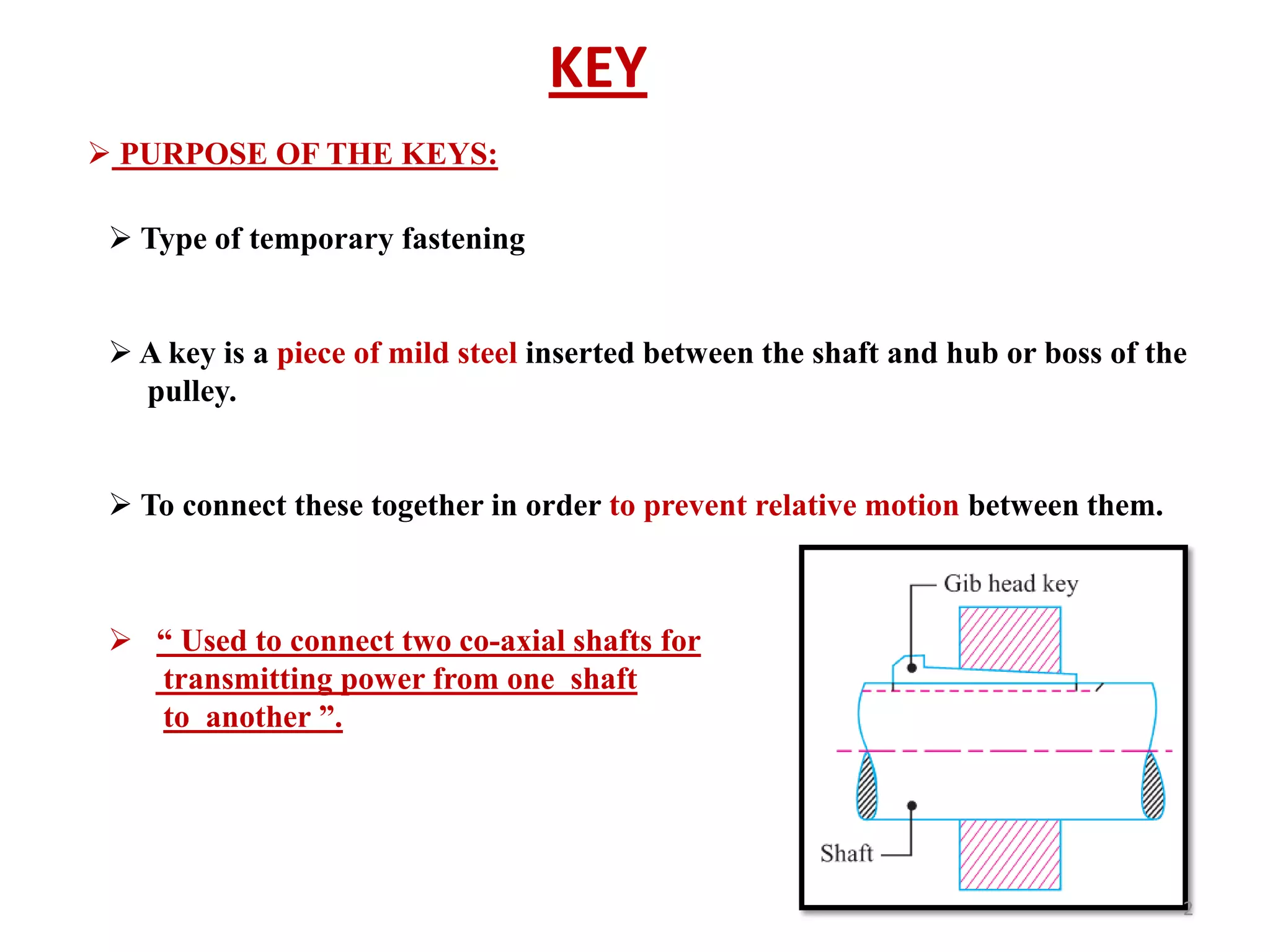

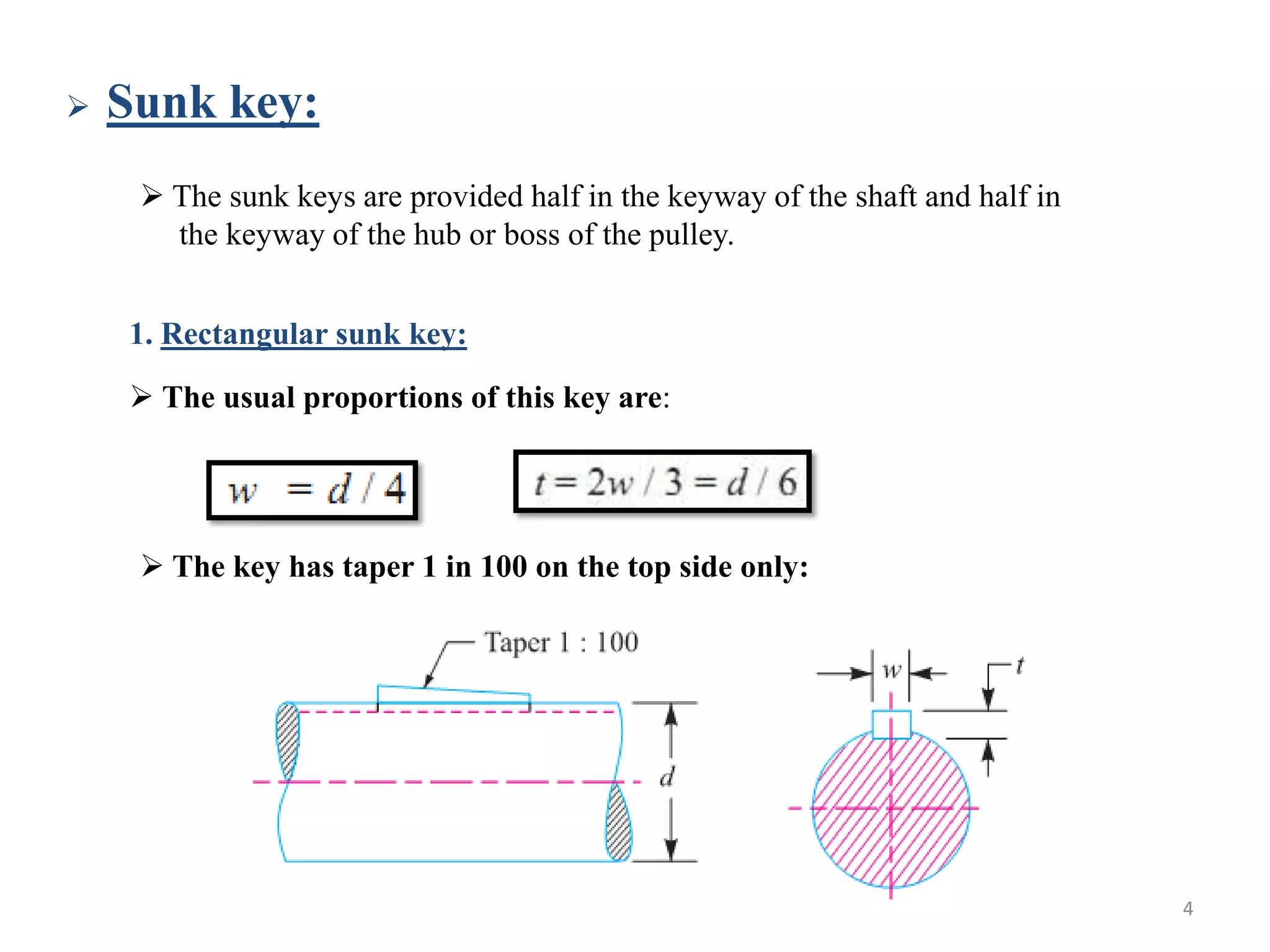

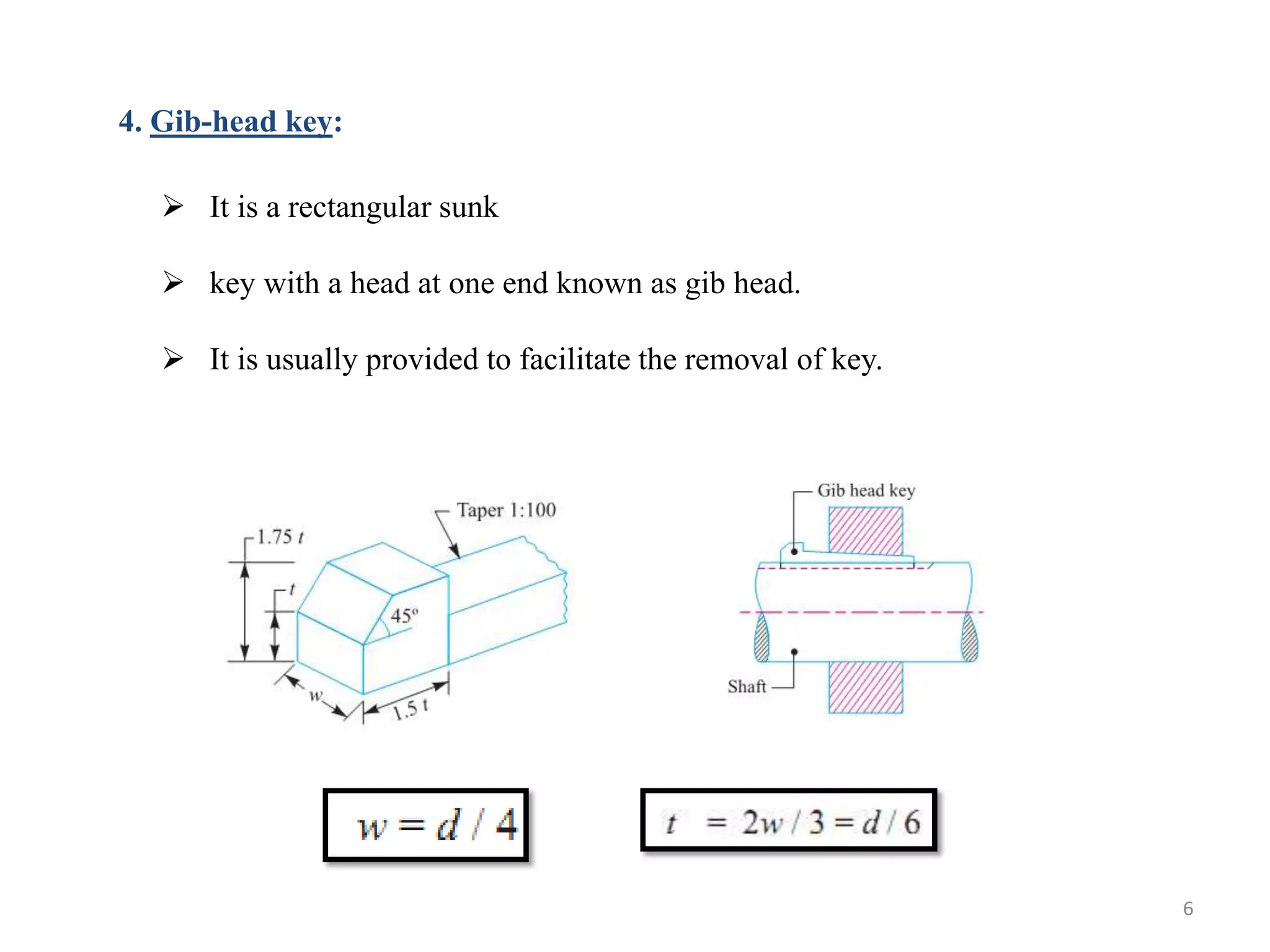
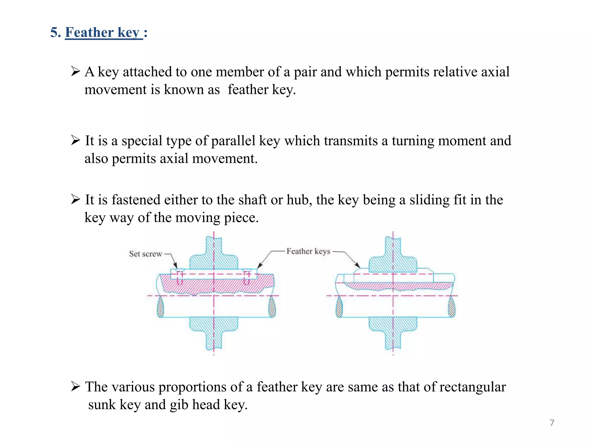


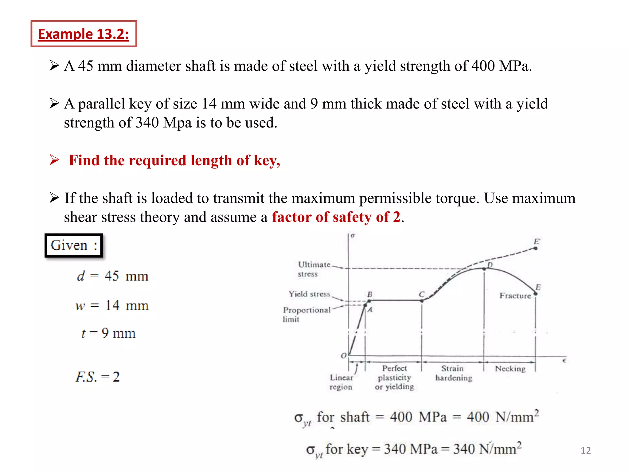


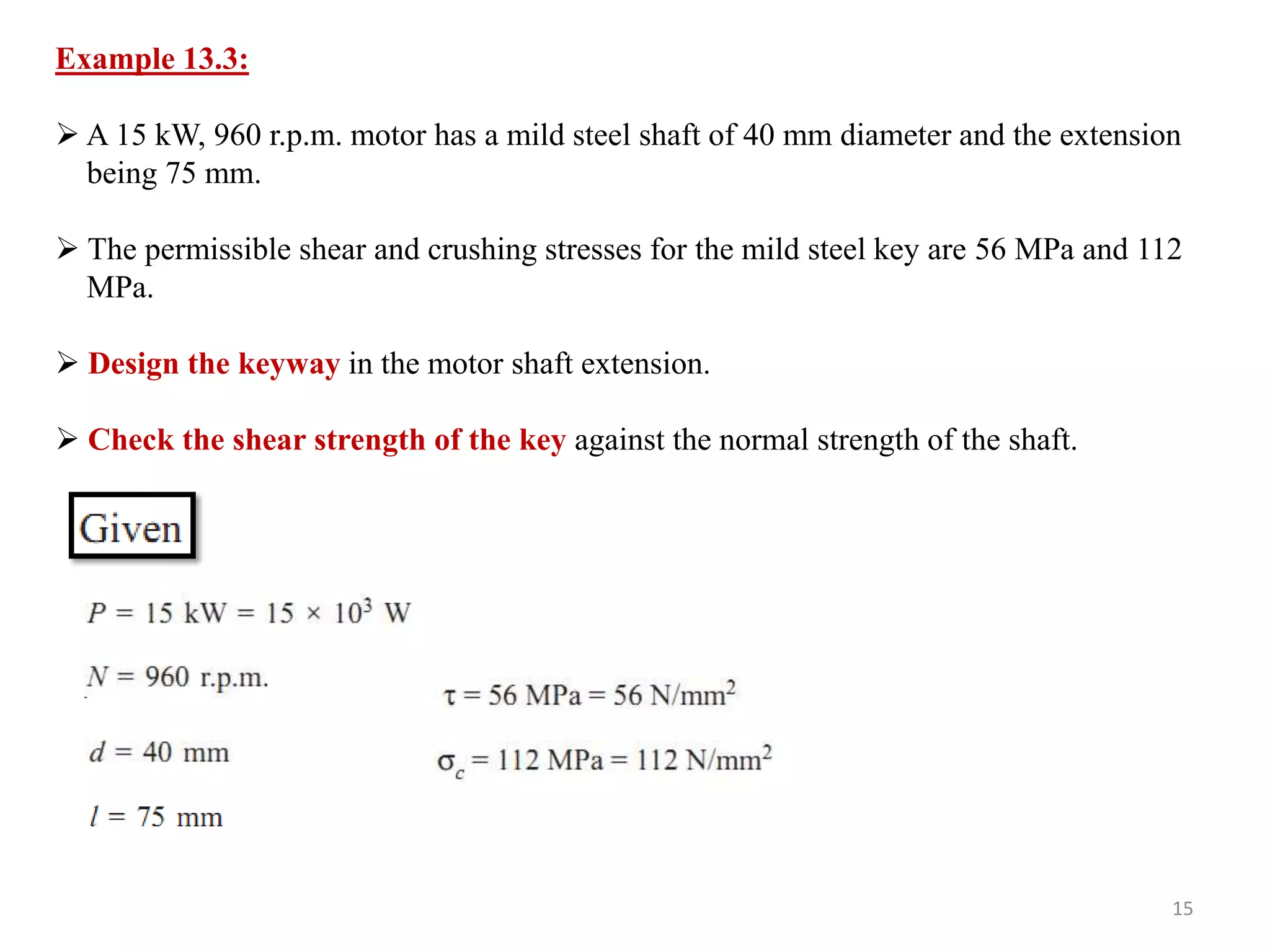


The document discusses different types of keys used to connect rotating shafts, including: - Sunk keys like rectangular, square, parallel, gib-head, feather, and woodruff keys - Saddle keys that are flat or hollow for lighter loads - Tangent keys fitted in pairs at right angles to withstand torque - Round keys that fit into drilled holes for low power drives It also covers splined shafts that have multiple integral keys for transmitting larger forces compared to a single keyed shaft. The keys are designed based on withstanding shear and crushing stresses from the transmitted torque.


