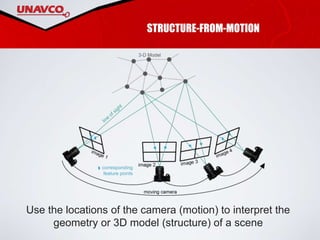
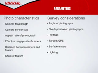
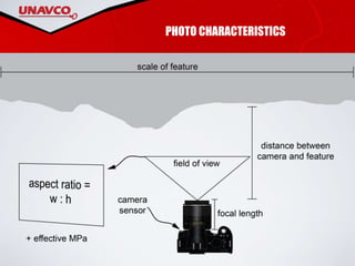
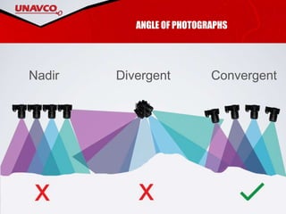
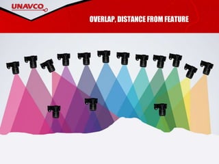
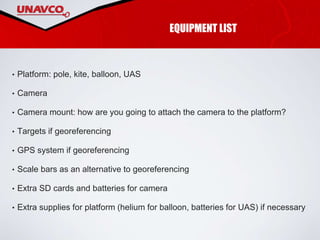
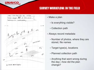
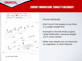
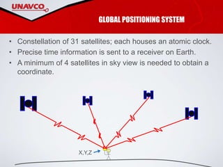
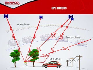
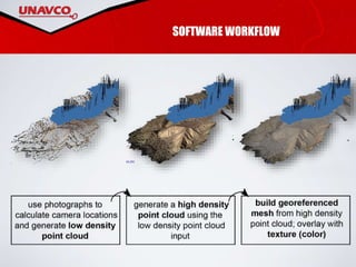
Kate Shervais
UNIT 1 STRUCTURE-FROM-
MOTION: WORKFLOW
STRUCTURE-FROM-MOTION
Use the locations of the camera (motion) to interpret the
geometry or 3D model (structure) of a scene
PARAMETERS
• Camera focal length
• Camera sensor size
• Aspect ratio of photograph
• Effective megapixels of camera
• Distance between camera and
feature
• Scale of feature
Photo characteristics
• Angle of photographs
• Overlap between photographs
• Platform
• Targets/GPS
• Surface texture
• Lighting
Survey considerations
PHOTO CHARACTERISTICS
ANGLE OF PHOTOGRAPHS
ConvergentDivergentNadir
OVERLAP, DISTANCE FROM FEATURE
PLATFORMS
PLATFORM SELECTION
1. How large is the area of interest?
2. What is financially feasible?
3. How large is the intended camera?
4. Is the survey collection path accessible or
will a UAS need to be used?
5. What additional components are needed
and does the field area support these? (i.e.,
batteries, helium, specific weather)
TARGETS
SURVEY WORKFLOW: BEFORE THE FIELD
• GPS network: identify base stations, benchmarks and make sure they are
operational!
• Understand field site, anticipate challenges you may encounter (complex
landscape, is power available in evenings, etc.)
• Give equipment a test run.
EQUIPMENT LIST
• Platform: pole, kite, balloon, UAS
• Camera
• Camera mount: how are you going to attach the camera to the platform?
• Targets if georeferencing
• GPS system if georeferencing
• Scale bars as an alternative to georeferencing
• Extra SD cards and batteries for camera
• Extra supplies for platform (helium for balloon, batteries for UAS) if necessary
SURVEY WORKFLOW: IN THE FIELD
• Make a plan
• Is everything visible?
• Collection path
• Always record metadata
• Number of photos, where they are
stored, file names
• Target type(s), locations
• Planned collection path
• Anything that went wrong during
the day—how did the plan
change?
SURVEY WORKFLOW: TARGET PLACEMENT
• Evenly distributed
• Don’t bunch the targets or put them
in a single straight line
• Example to the left shows a good
target distribution, because targets
are in every section
• Make sure targets are not obscured
by vegetation or other features
GLOBAL POSITIONING SYSTEM
• Constellation of 31 satellites; each houses an atomic clock.
• Precise time information is sent to a receiver on Earth.
• A minimum of 4 satellites in sky view is needed to obtain a
coordinate.
X,Y,Z
• Advantage is cm to sub-cm
precision!
• Base station and unknown
points must share same
occupation time
• Base stations and unknown
points must “see” same
errors (same sky view).
Practical limit is 100km.
• Vertical precision will always
be ~2x less precise than
horizontal precision.
GLOBAL POSITIONING SYSTEM
Uses known reference points (base stations) on the Earth to
provide corrections for unknown points.
GPS ERRORS
Multi-Path
Troposphere
Ionosphere
IMAGE QUALITY CHECK
SOFTWARE WORKFLOW

SfM Workflow Presentation

  • 1.
    Kate Shervais UNIT 1STRUCTURE-FROM- MOTION: WORKFLOW
  • 2.
    STRUCTURE-FROM-MOTION Use the locationsof the camera (motion) to interpret the geometry or 3D model (structure) of a scene
  • 3.
    PARAMETERS • Camera focallength • Camera sensor size • Aspect ratio of photograph • Effective megapixels of camera • Distance between camera and feature • Scale of feature Photo characteristics • Angle of photographs • Overlap between photographs • Platform • Targets/GPS • Surface texture • Lighting Survey considerations
  • 4.
  • 5.
  • 6.
  • 7.
  • 8.
    PLATFORM SELECTION 1. Howlarge is the area of interest? 2. What is financially feasible? 3. How large is the intended camera? 4. Is the survey collection path accessible or will a UAS need to be used? 5. What additional components are needed and does the field area support these? (i.e., batteries, helium, specific weather)
  • 9.
  • 10.
    SURVEY WORKFLOW: BEFORETHE FIELD • GPS network: identify base stations, benchmarks and make sure they are operational! • Understand field site, anticipate challenges you may encounter (complex landscape, is power available in evenings, etc.) • Give equipment a test run.
  • 11.
    EQUIPMENT LIST • Platform:pole, kite, balloon, UAS • Camera • Camera mount: how are you going to attach the camera to the platform? • Targets if georeferencing • GPS system if georeferencing • Scale bars as an alternative to georeferencing • Extra SD cards and batteries for camera • Extra supplies for platform (helium for balloon, batteries for UAS) if necessary
  • 12.
    SURVEY WORKFLOW: INTHE FIELD • Make a plan • Is everything visible? • Collection path • Always record metadata • Number of photos, where they are stored, file names • Target type(s), locations • Planned collection path • Anything that went wrong during the day—how did the plan change?
  • 13.
    SURVEY WORKFLOW: TARGETPLACEMENT • Evenly distributed • Don’t bunch the targets or put them in a single straight line • Example to the left shows a good target distribution, because targets are in every section • Make sure targets are not obscured by vegetation or other features
  • 14.
    GLOBAL POSITIONING SYSTEM •Constellation of 31 satellites; each houses an atomic clock. • Precise time information is sent to a receiver on Earth. • A minimum of 4 satellites in sky view is needed to obtain a coordinate. X,Y,Z
  • 15.
    • Advantage iscm to sub-cm precision! • Base station and unknown points must share same occupation time • Base stations and unknown points must “see” same errors (same sky view). Practical limit is 100km. • Vertical precision will always be ~2x less precise than horizontal precision. GLOBAL POSITIONING SYSTEM Uses known reference points (base stations) on the Earth to provide corrections for unknown points.
  • 16.
  • 17.
  • 18.

Editor's Notes

  • #2 All images in this Powerpoint were created by UNAVCO; there are no copyright permissions needed.
  • #3 As a review, Structure-from-Motion works by finding matching features in multiple photographs and then using the relative size and orientation of the matching features to construct the geometry of a scene. In this presentation, we will walk through the process of designing and conducting a survey as well as the steps in a SfM program to create a model. Image: Kate Shervais (Figure modified from Chris Sweeney, UCSB)
  • #4 Before beginning your survey, you need to consider a variety of factors that influence the data you collect. We will cover each of the factors listed above so you can keep these in mind as you design your own survey with the class today. These are also covered in the field manual in case you need a reminder in the future.
  • #5 Camera focal length Camera sensor size Aspect ratio of photograph Effective megapixels of camera Distance between camera and feature Scale of feature
  • #6 There are three ways to orient the photographs: nadir, or exactly orthogonal to the feature of interest in a plane; divergent, or with a rotating camera based in one location; and convergent, or converging on the scene. The nadir and divergent methods may actually create a model with some distortions. Image: Kate Shervais
  • #7 Photos also need to overlap. The amount of overlap depends on the specific software program, but approximately 60–80% overlap is needed. The other factor shown here is distance from the feature of interest; a range of photos both close and far away will add detail to the model without a large increase in processing power. Image: Kate Shervais
  • #8 We went over the details of the various SfM platforms in the previous presentation. However, the platform is an essential thing to consider for survey design as it controls the duration of the survey as well as the path needed to collect photos. A few questions to consider are here (next slide) Image: Kate Shervais
  • #9 How large is the area of interest? Larger areas of interest will need aerial platforms. The dimension of individual photographs will be large enough to not require an egregious amount of time to collect photographs. Smaller areas may be described by handheld or pole photography. 2. What is financially feasible? The platform should not be cost prohibitive; select a platform that is appropriate for the area of interest but also for your budget. 3. How large is the intended camera? The camera must be able to be supported by the platform. If using a DLSR (so higher resolution photographs) is more important to you, a platform like a balloon or pole may be more appropriate. If using a point and shoot, balloons with smaller amounts of lift or some UASs may be usable. 4. Is the survey collection path accessible or will a UAS need to be used? If the area is non-accessible, a UAS may need to be used instead. UASs should always be in your line of sight, but if they are and the area that needs to be photographed is hazardous, they are a more appropriate platform. 5. What additional components are needed, and does the field area support these? If batteries are needed to power the platform, these are only useful (for multi-day surveys) if you have a way to charge them or many, many batteries (cost-prohibitive). If using a kite, the weather needs to include enough wind to lift a kite, picavet camera mount, and camera. If using a balloon, helium is necessary (~180 dollars a canister). The helium will need to be transported or the balloon filled prior to approaching the field area.
  • #10 We need a way to link the survey to physical space. Otherwise, it is impossible to actually extract a measurement of the feature of interest because there is no scale. Using targets requires a survey grade GPS, much more precise than the GPS in your cell phone. More targets are better, because there is less error. Any ideas about other things to keep in mind when you set up targets? Where should they be in relation to each other? Class discussion [brief]. Ideally they will be triangular and also incorporate multiple elevations.
  • #11 SfM is frequently paired with GPS to link the three-dimensional point cloud to global coordinate systems. See what base stations exist in your area so you are able to collect GPS coordinates of the targets. We will go into more detail about how all this works later. If you have been to your field site before, think about how you are going to get the equipment there. If you are conducting a multiple-day survey, you will need to be able to charge equipment, too. Test run! The workflow for the scanner is pretty detailed. The more experience you have, the better. Think of today as your test run; if you’ll be doing more scans later in the week, today’s the day you run through and learn all the steps so you know how to work the equipment. Image: Google Maps and Plate Boundary Observatory Network Health site
  • #12 Once you have considered the GPS stations nearby and the accessibility of your site, check that you have all equipment before you leave for the field.
  • #13 Read the slide. You might look at data a few days later—it is hard to remember the details. Image: Chris Crosby
  • #14 [Read this slide.]
  • #15 Constellation of 31 satellites; each houses an atomic clock. Precise time information is sent to a receiver on earth. A minimum of 4 satellites in sky view is needed to obtain a coordinate. [This slide is fairly straightforward; the information off the slide is really all that needs to be included.]
  • #16 The typical GPS in your phone or that you purchase has 3–10 m precision. When you use a setup with a base station, that precision increases to cm to sub-cm! The base station has a continuously collected known location. When the receiver of the GPS communicates with the base station, your location will be known to cm precision. One thing: usually the base station needs to be visible to all locations, so needs to be at a high elevation. There are some errors with GPS though… Images: UNAVCO
  • #17 Error can be introduced into your GPS survey in a number of ways. Distortion could come from the [space bar] ionosphere, [space bar] troposphere, or from [space bar] “multi-path,” which simply means that the signal is reflected off something else before you receive it. Because the location is determined from the time it takes a signal to be received, these factors can distort your location. Do not set the GPS up somewhere where the signal will be distorted. NOT next to a car. NOT next to power line, not next to a tree. Don’t forget about the influence of clouds.
  • #18 Before starting the software workflow, you must do an image quality check. If an image is blurry, it is difficult for the algorithm to find matching features. The first image is clear enough to input into SfM software [spacebar] but this image of nearly the same thing is too blurry and obstructs the features. Image: UNAVCO
  • #19 The photographs, after a quality check, will be aligned. This means the matching features are found, generating a sparse point cloud and the camera locations. The next step is to generate the high density point cloud. This is one of the products you may end up using; millions of points will be in the point cloud, creating a very realistic model of the feature. This point cloud can be used to calculate a mesh. The “mesh” uses the points to create a surface composed of thousands of triangles. This mesh can be draped with the texture atlas, like draping a photograph. Image: UNAVCO