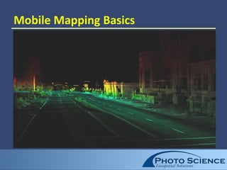
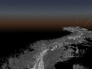
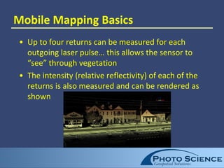
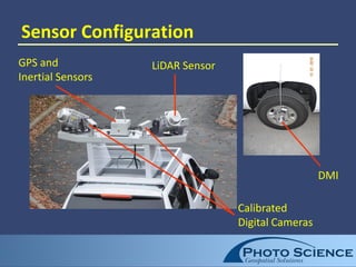
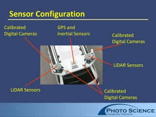
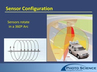
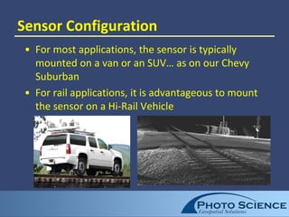
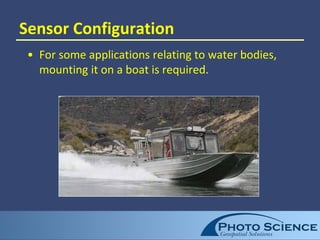
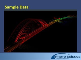
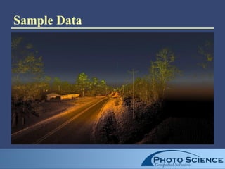
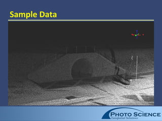
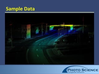
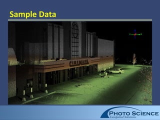
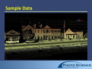
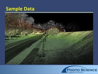
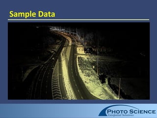
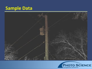
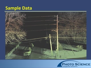
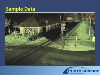
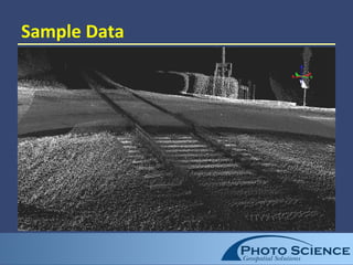
2. Presentation Outline
• Mobile Mapping Basics
• Mobile Mapping Applications
• Mobile Mapping Positioning
• Sensor Configuration
• Sensor Capabilities
• System Accuracies
• Feature Extraction
• System Limitations
• Sample Data
3. Mobile Mapping Basics
• Mobile Mapping is a highly accurate method of
spatial data collection
• The Mobile Mapping Sensor is mounted on a
mobile platform (SUV, boat, golf cart, ATV, etc.)
depending on the specific application
• The mobile platform is driven along a pre-planned
route to acquire a spatial model consisting of 3D
points (point cloud) of the project area along with
calibrated imagery
6. Mobile Mapping Basics
• The sensor collects the point cloud of all features
within a swath of 250 to 300 feet each side of the
path driven
• Swath width is limited by the relative low power of
the eye safe lasers
• Vehicle can be driven at posted road speeds
• To be useful, this 3D model must be both very
accurate and very dense
7. Mobile Mapping Basics
• Primary advantages are high productivity (miles per
day, etc.), increased safety (e.g., removing
surveyors from traffic on roadways), and high
accuracy
8. Mobile Mapping Basics
• After acquisition, the spatial model collected from
the sensor is used in the office environment to
extract very accurate feature information from the
point cloud
• This information might include topography,
utilities, structure locations, cross sections, bridge
clearances, signage, etc.
• Semi-automated feature extraction is critically
important to any mobile mapping project
9. Mobile Mapping Basics
• Up to four returns can be measured for each
outgoing laser pulse… this allows the sensor to
“see” through vegetation
• The intensity (relative reflectivity) of each of the
returns is also measured and can be rendered as
shown
10. Mobile Mapping Applications
• Any linear or corridor type project that requires
considerable accuracy and detail, that also has
reasonable access for maneuvering a mobile
vehicle
• Ideal applications include roadways, railways,
streams, piers, coastal (dunes, etc.), above ground
utilities, buildings, etc.
• Access is critical to the project’s success
11. Mobile Mapping Positioning
• GPS provides the 3D positioning of the sensors
(XYZ)
• Inertial Navigation Systems (INS) provides the 3D
rotation of the sensor (omega, phi, kappa)
• Distance Measurement Indicators (DMI) provides
the distance traveled
• The system has the ability to use dead reckoning
for brief GPS outages due to tunnels, overhanging
vegetation, etc. without significant accuracy
degradation
12. Sensor Configuration
• The typical configuration includes acquisition of
LiDAR (providing 3D positional information) from
two sensors (200,000 kHz Each)
• LiDAR uses a rotating laser beam and GPS/INS
positioning technology to measure the distance
and direction to objects
• Four digital cameras for imagery (5MP Each)
14. Sensor Configuration
LiDAR Sensors Calibrated
Digital Cameras
Calibrated
Digital Cameras
Calibrated
Digital Cameras
GPS and
Inertial Sensors
LiDAR Sensors
16. Sensor Configuration
• For most applications, the sensor is typically
mounted on a van or an SUV… as on our Chevy
Suburban
• For rail applications, it is advantageous to mount
the sensor on a Hi-Rail Vehicle
17. Sensor Configuration
• For some applications relating to water bodies,
mounting it on a boat is required.
18. Sensor Capabilities
• Today’s Mobile Mapping LiDAR sensors include the
ability to capture 400,000 to 500,000 points per
second of travel
• Soon (summer 2011), the LiDAR sensors will move
to capture rates up to 1 million points per second –
with dual 500 kHz lasers
• Each outgoing laser pulse is captured as an
accurate 3D position
19. Sensor Capabilities
• Very high point densities of 5,000 points per square
meter are possible near the driven path
• The point density will decrease somewhat at
increased distances from the sensor & speed
• At these very high densities it is possible to
recognize and position even very small features
along the route
• The lasers provide true 360 degree coverage,
allowing the accurate location of both ground-
based and aerial (overhead utilities, etc.) features
20. System Accuracies
• Accuracy depends on a number of factors (max GPS
baseline length, GPS configuration, PDOP, etc.)
• For the most demanding projects, horizontal and
vertical accuracies to 0.05’ can be achieved within
the point cloud from LiDAR
• Calibration points placed throughout the project,
with precise 3D positions are required to achieve
the highest of accuracies
• Project cost is directly related to accuracy and the
features to be extracted from the point cloud
21. Feature Extraction
• With point clouds often consisting of billions of
points, efficiently extracting intelligent vector data
from these point clouds is critical to a project’s
success
• Software has made significant strides in the last
year in managing and extracting data from the
cloud
• Extraction uses both elevation and intensity models
for automated routines
22. System Limitations
• The sensor is line-of-sight
• It can see through some vegetation, but can not
see behind buildings, embankments, etc.
• The system depends on GPS for positioning and
therefore tunnels, urban canyons, and overhanging
vegetation can pose challenges
• The system generates significant data… up to 90
MB per second currently with dual LiDAR and 4
metric digital cameras